1
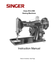
*
127-3 & 128-3
with VIBRATING SHUTTLE
Copyright, U. S. A., 1915, 1923, 1929, 1932, 1935
and 1940, by The Singer Manufacturing Company
All Rights Reserved for all Countries
*A Trade Mark of
THE SINGER MANUFACTURING CO.
INSTRUCTION MANUAL
Table of Contents
| Next Page
127-3 & 128-3
Table of Contents
Main Parts
Instructions for
Operating the Machines
To Remove the Shuttle
To Wind the Bobbin
To Thread the Shuttle
To Replace the Shuttle
To set the Needle
To Thread the Needle
To Prepare for Sewing
To Commence Sewing
To Remove the Work
Tensions
To Regulate the Tensions
To Turn a Corner
To Regulate the Length of Stitch
To Regulate the Pressure on the Material
To Sew Flannel or Bias Seams
A Stitch to Ravel Easily
Hints
The Belt
Machine Working Heavily
To Avoid Breaking Needles
Breaking Needle Thread
Breaking of Bobbin Thread
Skipping of Stitches
Instructions for
Using the Attachments
Foot Hemmer
-- Hemming
-- Hemming and
Sewing on Lace
-- Felling
Adjustable Hemmer
-- Hemming Wide Hemming
Binder -- Binding
Tucker
Ruffler
To Attach the Ruffler to the Machine
To Adjust the Ruffler for Gathering
To Make a Ruffle and Sew it
to a Gament in One Operation
Piping a Ruffle
To Adjust the Ruffler for Plaiting
To Adjust the Ruffler for Group
Plaiting and Gathering
To Oil the Ruffler
Relative Sizes of Needles and Thread
To Oil the Machine
Previous Page | Next Page
127-3 & 128-3
Main Parts
TO ALL WHOM IT MAY CONCERN:
The improper placing or renewal of the TradeMark "SINGER" or any
other of the Trade Marks of The Singer Manufacturing Company (all of
which are duly Registered Trade Marks) on any machine that has been
repaired, rebuilt, reconditioned, or altered in any way whatsoever outside
a SINGER factory or an authorized SINGER agency is forbidden.
Table of Contents
Previous Page | Next Page
3
127-3 & 128-3
To release the balance wheel (D, Fig. 3), turn
the stop motion screw (E, Fig. 3) over toward
Raise the presser foot (B, Fig. 3) by means of you. It will be necessary to hold the balance
wheel while loosening the stop motion screw.
the presser bar lifter (C, Fig 3) to prevent
injury to the foot (B, Fig. 3) and feed (A, Fig.
After releasing the balance wheel, place your
3).
feet upon the treadle and with the right hand
turn the balance wheel over toward you. This
will start the band wheel, treadle and pitman,
the sewing mechanism having been disconnected.
Instructions for Operating the Machines
Continue the motion thus begun by an alternate pressure of heel and toe, until a regular
and easy movement is acquired, and the balance wheel kept in continuous rotation by use
of the feet alone.
When you are thoroughly familiar with the
treadle movement and can restart the
machine without turning the balance wheel in
the wrong direction, tighten the stop motion
screw to connect the balance wheel with the
stitching mechanism.
FIG 3. FRONT VIEW OF THE MACHINE
It is necessary to understand the stop motion
(E, Fig. 3) by which the balance wheel (D,
Fig. 3) can be released when required, thus
enabling the operator to become proficient in
the use of the treadle and permitting the
winding of bobbins without running the stitching mechanism. It also allows the operator to
wind bobbins without removing partially sewn
work and without unthreading the machine.
Place a piece of cloth under the presser foot,
let the foot down upon it, and operate the
machine in this way without being threaded,
until you have become accustomed to guiding
the material.
Table of Contents
Previous Page | Next Page
4
127-3 & 128-3
To Remove the Shuttle
To Ensure Perfect Action of the Machine
Draw toward you the front slide in the bed of
the machine and turn the balance wheel over
toward you until the shuttle comes full under
the opening. Press the forefinger of the right
hand upon the shuttle ejector as shown in
Fig. 4, this will raise the shuttle so that it can
be easily taken out. Turn the open end of the
shuttle downward and the bobbin will drop
out.
The balance wheel must always turn over
toward the operator.
Do not run the machine with the presser foot
resting on the feed without cloth under the
presser foot.
Do not run the machine when both shuttle
and needle are threaded unless there is
material under the presser foot.
Do not try to help the machine by pulling the
fabric lest you bend the needle. The machine
feeds the work without assistance.
Both slides over the shuttle should be kept
closed when the machine is in operation.
FIG. 4. REMOVING THE SHUTTLE
Table of Contents
Previous Page | Next Page
5
127-3 & 128-3
To Wind the Bobbin
Release the balance wheel (D, Fig. 3) by
turning the stop motion screw (E, Fig. 3) over
toward you.
Draw to the left the knob (A, Fig. 6, page 7)
and place the bobbin between the cups (B
and C, Fig. 6), then release the knob. Push
the bobbin winder pulley (D, Fig. 6) against
the hub of the balance wheel, and turn the
balance wheel until the thread guide (4, Fig.
6) moves to the extreme right. Put the spool
of thread on the spool pin (1, Fig. 5). Pass
the end of the thread into the thread guide (2,
Fig. 5) at the top of the face plate, then up
into the lower eyelet (3, Fig. 6) of the bobbin
winder thread guide, into the notch (4, Fig. 6).
With the thumb and forefinger of the left hand
press the bobbin lightly to the left and place
the end of the thread between the bobbin and
the cup (C, Fig. 6) at the right. Then operate
the machine the same as for sewing. When
the bobbin is filled, remove it from the bobbin
winder, pull the bobbin winder away from the
hub of the balance wheel and turn the stop
motion screw over from you to connect the
stitching mechanism.
Fig. 5. MACHINE THREADED FOR
WINDING THE BOBBIN
FIG. 6 WINDING THE BOBBIN
Table of Contents
Previous Page | Next Page
6
127-3 & 128-3
To Thread the Shuttle
Hold the shuttle between the thumb and fingers of the left hand as shown in Fig. 7.
Place the bobbin into the shuttle with the
thread drawing toward the right from the side
of the bobbin nearest you, as shown in Fig. 7.
Place the forefinger of the left hand on the
end of the bobbin and draw the thread downward into the long slot in the shuttle as far as
it will go, as shown in Fig. 8.
Then draw the thread straight upward and
under the tension spring as shown in Fig. 9,
until the bobbin begins to unwind.
FIG. 7
FIG. 8
FIG. 9
Table of Contents
Previous Page | Next Page
7
127-3 & 128-3
To Replace the Shuttle
After threading, take the shuttle in the right
hand with the point toward you and the tension adjusting screw (1, Fig. 7, page 8)
upwards. Put the point of the shuttle into the
front end of the shuttle carrier as shown in
Fig. 10, and drop the shuttle into place, leaving a loose end of thread about three inches
long above the slide. When closing the slide,
leave just enough space for the thread to
pass through.
To Set the Needle
Turn the balance wheel over toward you until
the needle bar (E, Fig. 5) moves up to its
highest point, loosen the thumb screw (C,
Fig. 5) in the needle clamp (B, Fig. 5) and put
the needle up into the clamp as far as it will
go, with its flat side toward the right, then
tighten the thumb screw. To select the correct
needle. ??REFERENCE??
FIG. 10. REPLACING THE SHUTTLE
Table of Contents
Previous Page | Next Page
8
127-3 & 128-3
To Thread the Needle
SEE FIG. 11
Turn the balance wheel over toward you until
the thread take-up lever (4) is raised to its
highest point. Place the spool of thread on
the spool pin at the top of the machine, lead
the thread into the thread guide (1) at the top
of the face plate, down under and from right
to left between the tension discs (2), into the
small wire spring (3) at the left of the tension
discs, up and from front to back through the
hole in the end of the thread take-up lever
(4), down into the eyelet (5) in front of the
face plate, into the lower wire guide (6) then
from left to right through the eye of the needle (7).
Draw about two inches of thread through the
eye of the needle with which to commence
sewing.
FIG. 11. THREADING THE NEEDLE
Table of Contents
Previous Page | Next Page
9
127-3 & 128-3
To Prepare for Sewing
To Commence Sewing
With the left hand hold the end of the needle
thread, leaving it slack from the hand to the
needle. Turn the balance wheel over toward
you until the needle moves down and up
again to its highest point thus catching the
bobbin thread, draw up the needle thread and
the bobbin thread will come up with it through
the hole in the throat plate (see Fig. 12) Lay
both threads back under the presser foot and
close the slides.
Place the material beneath the presser foot,
lower the presser foot and commence to sew,
turning the balance wheel over toward you.
Remove the Work
Let the thread take-up lever rest at its highest
point, raise the presser foot and draw the fabric back and to the left, pass the threads over
the thread cutter (A, Fig. 12) and pull down
lightly to sever them. Leave the ends of the
threads under the presser foot.
FIG. 12. DRAWING UP THE BOBBIN THREAD
Table of Contents
Previous Page | Next Page
10
127-3 & 128-3
Tensions
To Regulate the Tensions
For ordinary stitching the needle and the bob- The tension on the needle thread should only
bin threads should be locked in the centre of
be regulated when the presser foot is down.
the thickness of the material, thus:
Having lowered the presser foot, turn the
small thumb nut (D, Fig. 5) at the front of the
tension discs over to the right to increase the
tension. To decrease the tension, turn the
FIG. 13. PERFECT STITCH
thumb nut over to the left.
If the tension on the needle thread is too
tight, or if that on the bobbin thread is too
loose, the needle thread will lie straight along
the upper surface of the material, thus:
FIG. 14. TIGHT NEEDLE THREAD TENSION
If the tension on the bobbin thread is too
tight, or if that on the needle thread is too
loose, the bobbin thread will lie straight along
the under side of the material, thus:
The tension on the bobbin thread is regulated
by the small screw (1, Fig. 7) near the point
of the shuttle. To increase the tension, turn
the screw over to the right. To decrease the
tension, turn the screw over to the left.
When the tension on the bobbin thread has
been once properly adjusted, it is seldom
necessary to change it, as a correct stitch
can usually be obtained by varying the tension on the needle thread.
FIG. 15. LOOSE NEEDLE THREAD TENSION
Table of Contents
Previous Page | Next Page
11
127-3 & 128-3
To Turn a Corner
To Sew Flannel or Bias Seams
Stop the machine with the needle at its lowest point. Raise the presser foot and turn the
work as desired, using the needle as a pivot.
Use a short stitch and as light a tension as
possible on the needle thread so as to leave
the thread loose enough in the seam to allow
the goods to stretch if necessary.
To Regulate the Length of Stitch
A Stitch to Ravel Easily
The length of stitch is regulated by the large
thumb screw (E, Fig. 6) on the front of the
arm near the bobbin winder.
can be made if desired, by having the tension
on the needle thread so light that the bobbin
thread will not draw into the goods but lie
straight, as shown in Fig. 15.
To lengthen the stitch, turn this screw over to
the right. To shorten the stitch, turn this screw
over to the left.
To Regulate the Pressure on the Material
For ordinary family sewing it is seldom necessary to change the pressure on the material.
If sewing fine silk or flimsy material, lighten
the pressure by turning the thumb screw (A,
FIG. 5) on the top of the machine over to the
left. To increase the pressure, turn the screw
over to the right. The pressure should be only
heavy enough to prevent the material from
rising with the needle and to enable the feed
to move the work along evenly; a heavier
pressure will make the machine run hard.
Table of Contents
Previous Page | Next Page
12
127-3 & 128-3
HINTS
Breaking of Needle Thread.
If the needle thread breaks
it may be caused by:
The Belt
See that the belt is not too tight; it should
always be tight enough not to slip. If too
loose remove the hook at one end, shorten
the belt and rejoin.
Machine Working Heavily.
If the machine runs hard after standing idle
for some time use a little kerosene in the oiling places, run the machine rapidly, then wipe
clean and oil.
Improper threading.
Tension being too tight.
The thread being too coarse
for size of needle.
The needle being bent, having a
blunt point, or being set incorrectly.
Breaking of Bobbin Thread.
If the bobbin thread breaks it may caused by:
To Avoid Breaking Needles.
Improper threading of the shuttle.
See that the presser foot or attachments are
Tension being too tight.
securely fastened by the thumb screw, Do not
sew heavy seams or very thick goods with
Skipping of Stitches.
too fine a needle. A large needle and thread
to correspond should be used on heavy work The needle may not be accurately set into the
needle bar or the needle may be blunt or
???REFERENCE???.
bent. The needle may be too small for the
thread in use.
See that the needle is not bent and avoid
pulling the material when stitching.
Table of Contents
Previous Page | Next Page
13
127-3 & 128-3
To Oil the Machine
To ensure easy running, the machine requires
oiling and if used continuously it should be
oiled each day. With moderate use all occasional oiling is sufficient. Oil should he
applied at each of the places shown by
arrows in Figs. 16 and 17. One drop of oil at
each point is sufficient. Oil holes are provided
in the machine for bearings which cannot be
directly reached.
To oil the mechanism under the slide, draw
the front slide (see Fig. 16) toward you and
after removing the lint and dust which may
have accumulated, put a few drops of oil on
the wick which is retained in the hole in the
bed of the machine. The slide should then be
closed.
FIG. 16. OILING POINTS
AT THE FRONT OF THE MACHINE
On the front of the machine at the left is a
small plate or cover (see Fig. 16) fastened by
a screw; loosen the screw, turn the plate
upward and fasten by tightening the screw;
turn the balance wheel slowly and oil the
movable parts inside, then turn the cover
down and fasten it as before.
Table of Contents
Previous Page | Next Page
14
127-3 & 128-3
To Oil the Machine continued...
On the back of the arm is a round plate or
cover, fastened by a thumb screw. Loosen
the screw, turn the plate upward and fasten
by tightening the screw; turn the balance
wheel slowly and oil the moving parts inside,
then turn the cover down and fasten it as
before.
To reach the parts underneath the bed, the
kilt must be thrown off the band wheel on the
machine stand. Or this purpose a belt shifter
is placed at the front of tile band wheel. By
pressing the belt shifter lever to the left and
working the treadle meanwhile, the belt is
released and the machine can then be turned
back on its hinges. The places to be oiled
are indicated in Fig. 17, by arrows pointing to
the oil holes and bearings.
FIG. 17. OILING POINTS IN BASE OF MACHINE
To oil the stand, put a drop of oil the centres
on which the band wheel and treadle work,
and both ends of the pitman rod, which con-
Table of Contents
Previous Page | Next Page
15
127-3 & 128-3
INSTRUCTIONS FOR USING THE ATTACHMENTS
FOOT HEMMER -- Hemming
Raise the needle to its highest point. Remove
the presser foot and attach the foot hemmer
in its place (see Fig. 18). Clip off the right
hand corner of the cloth, so that it will take
the roll easily, turn up the edge about a quarter of an inch, insert it in the mouth of the
hemmer and draw or push it along until under
the needle. Then let down the presser bar
and after taking two or three stitches, draw
gently on the ends of the threads to help the
work along till the feed catches it. In order to
produce a smooth even hem, the mouth of
the hemmer must be kept just full.
Fig. 18 shows also what is known as a bag
seam or fell, made by passing two pieces of
fabric through the hemmer together and hemming them down.
FOOT HEMMER
Hemming and Sewing on Lace
Start the hem as previously explained, and
when it is well started, raise the needle to its
highest point.
Raise the hemmer to relieve its pressure on
the hem, pass the end of the lace through the
slot in the side of the hemmer, under the
back of the hemmer and over the hem, as
shown in Fig 19.
Take care that the hem is not displaced in the
hemmer and that the needle goes down
through the lace and hem together. Then let
down the presser bar and guide tile lace over
the front of the hemmer, keeping it well into
the slot.
FIG. 18
FIG. 19
Table of Contents
Previous Page | Next Page
16
127-3 & 128-3
FOOT HEMMER -- Felling
The two pieces of cloth to be felled should be
laid one over the other, right sides together,
the edge of the under piece being a little farther to the right than the upper piece. Stitch
them together, using the hemmer as a presser foot, the front end of the hemmer forming a
guide for the edges of both pieces, the upper
piece being guided by the inside and the
under piece by the outside of the projecting
front of the foot hemmer (see Fig. 20). Then
open the work out flat, wrong side up, the
edges standing up straight, and taking the
edges near the beginning of the seam in the
right hand, and the ends of the threads in the
left hand draw the edges into the hemmer
which will turn them as in hemming. Guide
the second row of stitching by following the
first row with the inside of the projecting front
of the foot hemmer (see Fig. 21).
FIG. 20.
FIG. 21.
Table of Contents
Previous Page | Next Page
17
127-3 & 128-3
ADJUSTABLE HEMMER -- Hemming
ADJUSTABLE HEMMER -- Wide Hemming
Remove the presser foot and attach the
adjustable hemmer in its place as shown in
Fig. 22. This hemmer will turn hems from
3/16 inch to 15/16 in. wide The adjustment is
made by loosening the thumb screw on the
hemmer and moving the scale to the right or
left until the hem turned is of the desired
width. Place the cloth under the hemmer and
draw the edge toward the left under the
scale, as shown in Fig. 22. Draw the edge of
the cloth back and forth until the hem is
formed, stopping with the end under the needle. Lower the presser bar and commence to
sew, being careful to so guide cloth as to
keep hemmer full.
To make a hem more than 15/16 inch wide,
loosen the thumb screw in the hemmer and
move the scale to the right as far as it will go,
then swing it toward you as shown in Fig. 23,
and tighten the thumb screw. Fold and crease
down a hem of the desired width; pass the
fold under the extension at the right of the
hemmer, and the edge into the folder as
shown in Fig. 23, and proceed to stitch the
hem.
FIG. 23.
FIG. 22.
Table of Contents
Previous Page | Next Page
18
127-3 & 128-3
BINDER -- Binding
Remove the presser foot and attach the
binder in its place. Pass the binding through
the scroll of the binder and draw it back
under the needle. Place the edge of the
goods to be bound between the scrolls of the
binder and draw it under the needle. Lower
the presser bar and sew as usual. To make
French folds proceed as directed for binding
except that the fold is stitched on to the face
of the material instead of on the edge (see
Fig. 24). After loosening the binder set screw
and adjusting the binder the line of stitching
can he brought, nearer the centre, this being
more effective when making French folds.
FIG. 24.
Table of Contents
Previous Page | Next Page
19
127-3 & 128-3
TUCKER
Remove the presser foot and attach the tucker in its place. The width of the tuck is determined by the scale of figures nearest the
needle, which shows in eighths and sixteenths of an inch the distance of the edge of
the fold from the line of stitching.
The crease or mark for the second and following tucks is determined by the scale nearest the operator and this is set by the line in
front of the needle hole in the presser foot.
For blind tucks without spaces, adjust the
scale nearest the operator so that the figure
opposite the line on the presser foot will be
the same as that at which the guide is located on the scale nearest the needle. To make
spaces between the tucks, move the front
scale farther to the left until the desired space
is obtained.
Having adjusted the scales for tuck and
space as desired, fold the material and
crease by hand; pass the folded edge
between the spring and spur near you, then
between the two blades of the second scale,
and back under the presser foot; draw to tile
right against the guide, lower the presser bar;
see that the lever for the needle clamp to
strike is in its backward position so as to form
a crease for the next tuck, then proceed with
the first tuck.
For the second tuck, fold carefully at the
crease made by the spur and place the edge
of the first tuck underneath and against the
spur at the left. The spur will serve as a
guide and will also make a distinct crease for
the next tuck. Always place the last tuck
against the spur to ensure perfect work.
When making the last tuck, the lever
upon which the needle clamp strikes while
tucking should be raised to its highest point;
while the lever is in this position no crease for
a succeeding tuck is made upon the goods.
FIG. 25.
Table of Contents
Previous Page | Next Page
20
127-3 & 128-3
The names and uses of the
principal parts of the ruffler are as follows:
(SEE: REFERENCES IN Fig. 26)
A -- FOOT -- the part by which the ruffler is
attached to the presser bar.
B -- FORK ARM-- the section that must be
placed astride the needle clamp.
C -- ADJUSTING SCREW -- the screw that
regulates the fullness of the gather.
D -- PROJECTION -- the part that projects
through tile the slots in the adjusting
lever
FIG. 26. THE RUFFLER AND ITS PARTS
Ruffler
E-- ADJUSTING LEVER -- the lever that sets
the ruffler for gathering or for making a
plait once at every six stitches or once
at every twelve stitches, as desired: also
for disengaging the ruffler, when either
plaiting or gathering is not desired.
Lines 1, 2, 3, 4 and .5 shown in Fig. 26 indicate where the material is to be placed for
various operations, as follows:
Line 1 -- the correct position for the material
to which the ruffled material is
applied.
Line 2 -- material to be ruffled.
Line 3 -- the facing for the ruffle.
Line 4 -- the strip of piping material.
Line 5--the edge to be piped.
F -- ADJUSTING FINGER -- the part which
regulates the width or size of the plaits.
continued on next page...
Refer to Fig. 26 when inserting the material in
the ruffler.
Table of Contents
Previous Page | Next Page
21
127-3 & 128-3
Ruffler -- Principal Parts continued...
To Adjust the Ruffler for Gathering
H -- RUFFLING BLADE--the upper blue steel
blade with the teeth at the end to push
the material in plaits up to the needle.
The adjusting finger (F, Fig. 27) is not intended for gathering and should be moved forward or away from the needle, as shown in
Fig. 27.
J -- SEPARATOR BLADE--the lower blue
steel blade without teeth, which prevents the teeth of the ruffling blade
coming into contact with the feed of the
machine, or the material to which ruffling or plaiting is to be applied.
To Attach the Ruffler to the Machine
Raise tile needle bar to its highest point and
remove the presser foot. Attach the ruffler
foot, (A, Fig. 26)) to the presser bar by
means of the thumb screw, at the same time
placing the fork arm (B, Fig. 26) astride the
needle clamp as shown in Fig. 27.
Raise the adjusting lever (E, Fig. 27) and
move it to the left so that the projection (D,
Fig. 27) will enter the slot marked "1" in the
adjusting lever (E) when the lever is released.
The ruffling blade will then move forward and
back once at every stitch. Insert the material
to be ruffled between the two blue blades, following the line 2 in Fig. 26. Draw the material
slightly back of the needle, lower the presser
bar and commence to sew.
To make fine gathering, shorten the stroke of
the ruffling blade by turning the adjusting
screw (C, Fig. 27) upwardly, also shorten the
stitch. To make full gathering, lengthen the
stroke of the ruffling blade by turning the
adjusting screw (C) downwardly, also lengthen the stitch. By varying these adjustments,
many pleasing varieties of work can be
accomplished.
FIG. 27.
Table of Contents
Previous Page | Next Page
22
127-3 & 128-3
To Make a Ruffle and
Sew it to a Garment in One Operation
To Ruffle and Sew on
a Facing in One Operation
Insert the material to be ruffled between the
two blue blades, as shown in Fig. 28, following the line 2, in Fig. 26. Place the garment to
which the ruffle is to be attached, under the
separator blade, following the line 1, in Fig.
26. Proceed the same as for gathering.
Insert the material to be ruffled between the
two blue blades, following the line 2, in Fig,
26.. Place the garment to which the ruffle is
to be attached, under the separator blade,
following the line 1, in Fig. 26. Place the
material for the facing over the upper blue
blade, as shown in Fig. 29, following the line
3, in Fig. 26. The facing may be straight or
bias material. If the facing is to be on the right
side of the garment, place the garment and
the ruffle so that the wrong sides are together. If the facing is to be on the wrong side,
place the right sides of the garment and the
The edge of the ruffled seam can be bound
by using the builder.
FIG. 28.
FIG. 29.
Table of Contents
Previous Page | Next Page
23
127-3 & 128-3
To Adjust the Ruffler for Plaiting
Piping a Ruffle
Raise the adjusting lever (E, Fig. 31) and
move it to the right so that the projection (D,
Fig. 31) will enter the slot marked "6" in the
adjusting lever when the lever is released.
The ruffling blade will then move forward and
back once at every six stitches. To adjust the
ruffling blade to make a plait once at every
twelve stitches, place the adjusting lever (E,
The material for piping must measure about
Fig. 31) so that the projection (D) enters the
1/4 inch wide when folded in the centre and
slot marked "12" in the adjusting lever. Insert
is usually cut on the bias. Place the piping
the material to be plaited between the two
material in the ruffler, following the line 4, in
blue blades, following the line 2, (Fig. 26).
Fig. 26, with the folded edge of the piping to
the right. The material to which the piping and The size or width of plaits is regulated by the
adjusting screw (C, Fig. 31) and the adjusting
ruffling are to be sewn should be folded on
finger (F, Fig. 31). To make a wider plait,
the edge and inserted in the ruffler, following
move the adjusting finger (F) back or toward
the line 5, in Fig. 26.
the needle and turn the adjusting screw (C)
downwardly. To make a smaller plait, turn the
adjusting screw (C) upwardly. The distance
between plaits is regulated by the length of
stitch.
Insert the material to be ruffled between the
two blue blades, following the line 2, in Fig.
26. This material must not be over 1 1/4 inches wide, as it is carried through the ruffler
with the finished edge of the ruffle to the right
of the attachment as shown In Fig. 30
FIG. 30.
FIG. 31.
Table of Contents
Previous Page | Next Page
24
127-3 & 128-3
To Adjust the Ruffler for
Group Plaiting and Gathering
The ruffler can be adjusted for group plaiting
by lifting the adjusting lever (E Fig. 32) and
moving it to the right so that the top of the
projection (D, Fig. 32) engages the small slot
indicated by the star on the adjusting lever.
This should be done at the points where you
wish to make the space between the plaits.
The ruffler will then stop and plain stitching
will be made. When the desired space has
been made, adjust the lever (E) so that the
projection (D) enters either the slot marked
"6" or the slot marked "12." By alternately
making groups of plaits and plain spaces, as
shown in Fig. 32, very attractive work can be
produced.
To Oil the Ruffler
Occasionally apply a drop of oil to the working parts of the ruffler at each of the places
indicated by arrows in Fig. 32. After oiling,
operate the ruffler on a waste piece of material to prevent the oil soiling the work. If the ruffler does not plait evenly, a drop of oil may
remedy the trouble.
SINGER Needles should be used
in SINGER Machines.
These Needles and their Containers
are marked with the Company's Trade Mark
"SIMANCO"*
Needles in Containers marked
"FOR SINGER MACHINES”
are NOT SINGER made Needles.
FIG. 32.
Table of Contents
Previous Page | Next Page
25
127-3 & 128-3
RELATIVE SIZES OF NEEDLES AND THREAD
(Class and Variety of Needles Used, 15x1)
CLASSES OF WORK
SIZES OF
NEEDLES
9
11
Georgette, chiffon, net, light weight synthetic,
fabrics, fine dimity, lawn, batiste, and other featherweight or sheer fabrics. For infants' clothes
and for dainty lingerie; also fine lace and all delicate or gossamer fabrics.
14
16
18
19
All medium, light weight summertime fabrics.. For
children's clothes, dainty washable dresses and
aprons, glass curtains.
Light weight woolens, firm dress silks and cottons, draperies and
fabric furnishings.. For smocks and men's fine
shirts. For general household for fine quilting.
Heavy cretonne, madras, muslin, damasks and
quilts. For stitching aprons and men's work
shirts.
SIZES OF COTTON,
SILK OR LINEN
THREAD
100 to 150 Cotton
OO & OOO Silk Twist
80 to 100 Cotton
O Silk Twist
56-3 Nylon
60 to 80 Cotton
C Silk Twist
30 to 40 Cotton
D Silk Twist
24 to 30 Cotton
E Silk Twist
60 to 80 Linen
Heavy weaves of coating, canvas, bed ticking,
awnings, porch furniture covers, boys' duck suits,
work or sports uniforms.
Suiting, ticking, sacking, tarpaulin, duck, drilling.
For wash uniforms and bedding supplies for hospitals and hotels.
When sending orders for needles be sure to specify thread size required.
Table of Contents
Previous Page
26