1
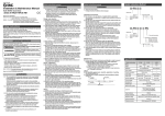
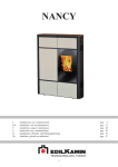
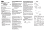
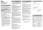
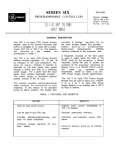
D-#S-TFK20GB
Safety Instructions (continued)
Installation & Maintenance Manual
Auto Switch (Solid State)
Series D-M9NA / D-M9NAV
D-M9PA / D-M9PAV
D-M9BA / D-M9BAV
EMC Directive 89/336/EEC
EN61000-6-2:2001 Electromagnetic Compatibility (EMC).
Generic standards - lmmunity for industrial environments.
EN55011 A1+A2:2001 Limits and methods of measurement of radio disturbance
characteristics of industrial, scientific and medical
radio-frequency equipment and light industrial environments.
Safety Instructions
This manual contains essential information for the protection of users and
others from possible injury and property damage.
To ensure correct handling, please follow the instructions.
Please check that you fully understand the meaning of the following
messages (signs) before going on to read the text, and always follow the
instructions.
Please read the Installation & Maintenance Manual of related apparatus and
understand it before operating the unit.
IMPORTANT MESSAGES
Read this manual and follow its instructions.
Titles such as DANGER, WARNING, CAUTION and NOTE, will be followed by
important safety information which must be carefully followed.
ACHTUNG
In extreme conditions, there is a possible result of
serious injury or loss of life.
WARNING
Indicates a potentially hazardous situation which
could result in death or serious injury if you do not
follow instructions.
CAUTION
Indicates a potentially hazardous situation which if
not avoided, may result in minor injury or
moderate injury.
1.1 General recommendation
These safety instructions are intended to prevent a hazardous situation
and/or equipment damage.
These instructions indicate the level of potential hazard by label of
"Caution", "Warning" or "Danger".
To ensure safety, be sure to observe ISO4414 (Note1), JIS B 8370
(Note2) and other safety practices.
(Note 1):ISO 4414:Pneumatic fluid power - Recommendations for the application
of equipment to transmission and control systems.
(Note 2):JIS B 8370:Pneumatic system axiom.
WARNING
1.1.1. The compatibility of pneumatic equipment is the responsibility
of the person who designs the pneumatic system or decides
its specifications.
Since the products specified here are used in various operating
conditions,their compatibility for the specific pneumatic system must
be based on specifications or after analysis and/or tests to meet your
specific requirements.
1.1.2. Only trained personnel should operate pneumatically operated
machinery and equipment.
Compressed air can be dangerous if an operator is unfamiliar with it
Assembly, handling or repair of pneumatic systems should be
performed by trained and experienced operators.
1.1.3. Do not service machinery/equipment or attempt to remove
component until safety is confirmed.
1) Inspection and maintenance of machinery/equipment should only be
performed after confirmation of safe locked-out control positions.
2) When equipment is to be removed, confirm the safety process as
mentioned above. Switch off air and electrical supplies and exhaust all
residual compressed air in the system.
3) Before machinery/equipment is re-started, ensure all safety measures to
prevent sudden movement of actuators etc. (Supply air into the system
gradually to create backpressure, i.e. incorporate a soft-start valve).
1.1.4. Contact SMC if the product is to be used in any of the following
conditions:
1) Conditions and environments beyond the given specifications, or if
product is used outdoors.
WARNING
2) Installations in conjunction with atomic energy, railway, air navigation,
vehicles, medical equipment, food and beverage, recreation equipment,
emergency stop circuits, press applications, or safety equipment.
3) Equipment intended for use in potentially explosive atmospheres.
Applications which have the possibility of having negative effects on
people, property or animals.
Special safety analysis is required.
Model Indication Method
Safety Instructions (continued)
WARNING
D-M9
Avoid incorrect wiring
If wiring is incorrect, the switches will be damaged.
When stripping the cable envelope, please pay attention to the
stripping direction.
Switch No.
Insulator might be split or hurt depending on the directions.
Confirm the specifications.
Take precautions when multiple actuators are used close together.
When multiple auto switch actuators are used in close proximity,
magnetic field interference may cause the switches to malfunction.
Maintain a minimum actuator separation of 40mm.
Pay attention to the length of time that a switch is ON at an
intermediate stroke position.
When an auto switch is placed at an intermediate position of the stroke and
a load is driven at the time the piston passes, the auto switch will operate,
but if the speed is too great the operating time will be shortened and the
load may not operate properly. The maximum detectable piston speed is:
Autoswitch operating range [ms]
V [mm/s]
Load operating time [ms]
Keep wiring as short as possible
Although longer wiring does not affect the function, please keep it to
100m or shorter
Do not use a load that generates surge voltage.
Water -resistant type
Do not use in an area where a magnetic field is generated.
Do not use in an environment where the auto switch will be
continually exposed to water.
Although switches satisfy IEC standard IP67 construction (JIS C 0920:
watertight construction), avoid using switches in applications with continual
exposure to water splash or spray. Poor insulation or swelling of the potting
resin inside switches may cause malfunction.
Do not use in an area where surges are generated.
When there are units (solenoid type lifter, high frequency induction furnace,
motor, etc.) which generate a large amount of surge in the area around
actuators with solid state auto switches, this may cause deterioration or
damage to the switches. Avoid sources of surge generation and crossed lines.
Ensure sufficient clearance for maintenance activities.
Avoid accumulation of iron waste or close contact with magnetic
substances.
Do not carry an actuator by the auto switch lead wires.
Never carry an actuator by its lead wires. This may not only cause broken
lead wires, but it may cause internal elements of the switch to be damaged
by the stress.
Mount switches using the proper tightening torque.
If a switch is tightened beyond the range of tightening torque, the mounting
screws, mounting brackets or switch may be damaged.
On the other hand, tightening below the range of tightening torque may
allow the switch to slip out of position.
Mount a switch at the center of the operating range.
Adjust the mounting position of an auto switch so that the piston stops at
the center of the operating range (the range in which a switch is ON).
(The mounting position shown in the catalog indicates the optimum
position at stroke end.) If mounted at the end of the operating range
(around the borderline of ON and OFF), operation may be unstable.
Broken lead wires can result from wiring patterns which repeatedly apply
bending stress or stretching force to the lead wires.
Confirm proper insulation of wiring.
Be certain that there is no faulty wiring insulation (contact with other
circuits, ground fault, improper insulation between terminals, etc.)
Damage may occur due to excess current flow into a switch.
Do not wire with power lines or high voltage lines.
Wire separately from power lines or high voltage lines, avoiding parallel wiring
or wiring in the same conduit with these lines. Control circuits containing auto
switches may malfunction due to noise from these other lines.
Do not allow short circuit of loads.
All models of switches do not have built-in short circuit protection circuits.
Note that if a load is short circuited, the switch will be instantly damaged
because of excess current flow into the switch.
A
PC
Output
3wire NPN output
3wire PNP output
2wire
Pre-wired connector
Connector pin assignment
A
M8-3pin connector
B
M8-4pin connector
D
M12-4pin connector
Water -resistant type
Electrical entry
No number
In line
V
Perpendicular
Lead wire length
S
0.5m
M
1m
Consult SMC if switches are used where there are temperature cycles
other than normal air temperature changes, as there may be adverse
effects inside the switches.
When a large amount of iron waste such as machining chips or spatter has
accumulated, or a magnetic substance (something attracted by a magnet) is
brought into close proximity with an auto switch actuator, it may cause auto
switches to malfunction due to a loss of the magnetic force inside the
actuator.
Maintenance
Perform the following maintenance periodically in order to prevent
possible danger due to unexpected auto switch malfunction.
1) Securely tighten switch mounting screws.
If screws become loose or the mounting position is dislocated,
retighten them after readjusting the mounting position.
2) Confirm that there is no damage to lead wires.
To prevent faulty insulation, replace switches or repair lead wires,
etc., if damage is discovered.
Others
For durability against water, elasticity, application at welding
site, please consult us.
If ON and OFF position (hysteresis) cause problems, please
consult us.
ON position
Piston moving direction
Wiring
Avoid repeatedly bending or stretching lead wires.
N
P
B
Consult SMC if auto switches are to be used in an environment with
coolant, cleaning solvent, various oils or chemicals. If auto switches are
used under these conditions for even a short time, they may be adversely
affected by improper insulation, malfunction due to swelling of the potting
resin, or hardening of the lead wires.
When an auto switch is used for an interlock signal requiring high reliability,
devise a double interlock system to avoid trouble by providing a mechanical
protection function, or by also using another switch (sensor) together with the
auto switch. Also perform periodic maintenance and confirm proper operation.
Do not drop, bump or apply excessive impacts (1000m/s2 or more for solid
state switches) while handling. Although the body of the switch may not be
damaged, the inside of the switch could be damaged and cause a malfunction.
In line
Perpendicular
Switch No.
Do not use in an environment with oil or chemicals.
Cautions for use in an interlock circuit
Do not drop or bump.
D-M9
Auto switches can malfunction or magnets inside actuators can become
demagnetized.
Do not use in an environment with temperature cycles.
Mount / adjustment
Electrical entry
No number
V
Operating environment
Although a zener diode for surge protection is connected at the output side of
a solid state auto switch, damage may still occur if the surge is applied
repeatedly. When a load such as a relay or solenoid which generates surge is
directly driven, use a type of switch with a built-in surge absorbing element.
When designing an application, be sure to allow sufficient clearance for
maintenance and inspections.
Lead wire length
No number
0.5m
M
1m
L
3m
Z
5m
Output
3wire NPN output
3wire PNP output
2wire
N
P
B
Design and selection
Read the specifications carefully and use this product appropriately.
The product may be damaged or malfunction if it is used outside the
range of specifications for load current, voltage, temperature or impact.
A
Specification
Switch model
number
D-M9NA
Wiring
Power voltage
Current
consumption
-
IC circuit/Relay/PLC
24V DC Relay/PLC
5/12/24V DC (4.5 to 28V DC)
-
10mA or less
-
Load current
40mA or less
Internal
voltage drop
0.8V or less at load current of 10mA
24V DC(10 to 28V DC)
2.5 to 40mA
(2V or less at load current of 40mA)
100 A or less at 24V DC
4.0V or less
0.8mA or less
Operating time
1ms or less
Indication light
Operating position : The red LED lights up.
Optimum operating position : The Green LED lights up.
Electrical entry
system
Lead wire
OFF position
PNP
28V DC or less
Current leakage
D-M9BAV
2 wire
NPN
Application
Load voltage
D-M9PA D-M9PAV D-M9BA
3 wire
Output
Hysteresis
Piston moving direction
D-M9NAV
Impact
resistance
Insulation
resistance
Withstand
voltage
Ambient
temperature
Protection
structure
Grommet
Vinyl sheath cable
2.7 3.2 oval, 0.15mm2, 2 wire (D-M9BA(V)), 3 wire (D-M9NA(V), D-M9PA(V))
1000m/s2
50M
or more under the test voltage 500V DC (between case and cable)
1000V AC for 1 minute (between case and cable)
-10 to 60
IEC60529 criteria IP67, JISC0920 watertight construction
D-#S-TFK20GB
Names and Functions of Individual Parts
Internal Circuit and Wiring
D-M9NA / D-M9PA / D-M9BA
D-M9NA(V)
Other Functions
When detection failure occur(stay ON/OFF), please check based on the following flow chart.
D-M9PA(V)
Brown[1]
Load
Switch main circuit
Brown[1]
Problem occurs
Switch main circuit
Black[4]
Load
Power suppy
Indicator light
Power supp
Black[4]
Problem
condition
Blue[3]
Stay OFF(sometimes ON)
Half strip treatment
Blue[3]
NA
D-M9
Mounting screw
(M2.5 4L)
Vinyl sheath cable
SMC
Load
Switch main circuit
Power suppy
Blue[4]
2wires / 3wires
Indicator light
4
1
3
V
BA
M9
D-
3wires
2wires
Replace the Switch
Load spec.check(2)
Normal
Abnormal
A
C
Normal Abnormal
Normal
Abnormal
A
F
Wiring (output)
check
2
1
3
4
Normal
Abnormal
A
B
D
E
B
B
A
D
4
M8-4pin connector
Load spec. check(1) ----- ON voltage > Load voltage-Internal voltage drop
Load spec. check(2) ----- OFF current > Leak current
M12-4pin connector
SMC
Installation
Outline with Dimensions (in mm)
6.How to mount / Mounting bracket
D-M9NA/ D-M9PA / D-M9BA
A
--- Switch output parts failure(replace)
B
--- Check wiring and correct fault
C
--- Replace switch 2 wires --> 3 wires
D
--- Switch failure
E
--- Replace cylinder. Detectable magnet field in adequate (No magnet)
F
--- Replace PLC input board or replace switch 2 wires --> 3 wires
Exterior dimension of Pre-wired connector
A
D-M9 A
B PC
Connector size M8
Mounting screw M2.5Ļ4
Slotted screw
Indicator light
φ10
Part no.(D-M9BA)
4
Manufacturing code
SMC
D-M9BA YY
2.7
2.8
32.7
24
Mounting screw
D-M9
500(1000)(3000)(5000)
A
DPC
Connector size M12
3.2
0.2
Actuator
Load spec.check(1)
3wires
2
3
M8-3pin connector
Abnormal
2wires
Blue[4]
Connection with PLC (sequence controller)
1
Normal
2wires / 3wires
Normal
Power supp
Load
D-M9NAV / D-M9PAV / D-M9BAV
Vinyl sheath cable
Source voltage or
load voltage
Normal
Brown[1]
Switch main circuit
Sensor unit
Stay OFF
Stay OFF
Stay ON
D-M9BA(V) (Source input mode)
Brown[1]
Each actuator has a specified mounting bracket when
mounted to the autoswitch.
“How to mount/Mount bracket” depends on actuator type and
tube I.D. Please refer to the actuator catalogue.
When an auto switch is mounted for the first time, please
ensure the actuator is a magnet built-in type, then ensure
brackets correspond to the actuator.
Indicator light
Indicator light
D-M9BA(V) (Sink input mode)
Mounting screw
(M2.5 4L)
Stay ON(Sometimes OFF)
6
φ14
3
4
Most sensitive position
Switch
D-M9NAV / D-M9PAV/ D-M9BAV
8
3.2
2.8
2
4
SMC
2.7
22
M2.5 mount screw tightening torque shall be 0.05 to 0.15N•m
2.6
Manufacturing code
Part no.(D-M9NAVâ
D-M9NAV
9.3
Set the actuator at the stroke end. Set the switch in the area to where
the auto switch red lamp lights. (Detecting actuator end)
Based on A and B dimensions in the actuator catalogue, set the switch.
YY
4
6
500(1000)(3000)(5000)
Slotted screw
4.6
Indicator light
Mounting screw M2.5Ļ4
•Setting the detecting position
42.5
Most sensitive position
Manufacture’s batch marking
Mark
K
L
M
N
O
P
Q
Year
Year
2006
2007
2008
2009
2010
2011
2012
Month
Mark Month
January
O
February
P
March
Q
April
R
May
S
June
T
July
U
August
V
W September
X
October
Y November
Z December
When you inquire about the product, please contact to followings.
URL http : // www.smcworld.com
Phone
AUSTRIA / (43) 2262-62 280
BELGIUM / (32) 3-355 1464
CZECH REP. / (420) 5-414 24611
DENMARK / (45) 70 25 29 00
FINLAND / (358) 207 513 513
FRANCE / (33) 1-64 76 1000
GERMANY / (49) 6103 4020
GREECE / (30) 1- 342 6076
HUNGARY / (36) 1-371 1343
IRELAND / (353) 1-403 9000
ITALY / (39) 02-92711
NETHERLANDS / (31) 20-531 8888
NORWAY / (47) 67 12 90 20
POLAND / (48) 22-548 50 85
PORTUGAL / (351) 2 610 89 22
SPAIN / (34) 945-18 4100
SWEDEN / (46) 8-603 0700
SWITZERLAND / (41) 52-396 3131
TURKEY / (90) 212 221 1512
UNITED KINGDOM / (44) 1908-56 3888
Specifications are subject to change without prior notice and any obligation on the
part of the manufacturer.
The descriptions of products shown in this document may be used by the other
companies as their trademarks.
© 2006 SMC Corporation All Rights Reserved