1
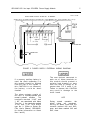
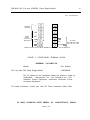
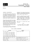
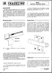
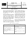
SERIES SIX
GFK-0065
PROGRAMMABLE CONTROLLERS
Source Voltage
100 to 150 V dc
Output Voltage
125 V DC INPUT CPU POWER
SUPPLY MODULE
+5, +12, -12 V dc
GENERAL DESCRIPTION
The 125 V dc Input CPU Power Supply
Module, used in the Central Processor Unit
(CPU), is available to be used with a power
source from 100 to 150 V dc. The features
and
benefits of
this
module
are
summarized in Table 1.
The 125 V dc Input CPU Power Supply
Module provides regulated +12, -12 and +5
dc voltages to the rack backplane. The
input (or source voltage) is applied to
terminals on the front panel, then routed
through a switch and fuse to a switching
power supply. For a given load the input
power drain remains essentially constant
The power supply is protected against
polarity reversal of the dc Input.
The module provides electromechanical
relay contacts f o r c o n n e c t i o n t o u s e r
indicators, or any device to be activated
during an alarm condition. The module also
provides a voltage r e g u l a t o r f o r a n
opt ional, auxiliary battery that provides
battery
back-up of
Complementary
Metal-Oxide
Semiconductor
(CMOS)
memory contained in the processor rack.
A Keyswitch mounted on the front panel
is used to select either the RUN or the
STOP mode for the processor; a second
Keyswitch allows the user to protect the
contents of the processor memories by
placing them i n a R E A D O N L Y m o d e .
The
same
operates
both
key
Keyswitches. Refer to Table 2 for the
CPU Power Supply module specifications.
The 125 V dc input CPU Power Supply
Module may be used in place of a 115/230
V ac or a 24 V dc Input CPU Power
Supply Module in an existing rack if 125 V
dc input is desired.
TABLE 1. FEATURES AND BENEFITS
FEATURES
BENEFITS
Uses dc input power source.
Extends power source compatibility to
125 V dc systems.
Can be used in any CPU rack.
Reduced spare-parts inventory.
Provides electromechanical-relay
tacts for alarm indications.
con-
Contains voltage regulator for auxiliary battery.
Activates
cators.
user-supplied
power
indi-
External battery back-up of CMOS
memory.
2
GFK-0065 125 V dc Input CPU/DPU Power Supply Module
Table 2. SPEClFlCATlONS
Altitude:
Input: 100 to 50 V dc, 2 A max.
Total power
from all
outputs
must be
1 less than
90 watts.
Output number 4 rated at 12.0 V dc
nominal when output supply currents are:
(I) +5 V dc @ 8.0 A
(2) +12 V dc @ 1 .0 A
(3) -12 V dc @ 0.5 A
(4) +12 V dc @ 1.0 A
1.
2.
3.
4.
output:
+5 V dc, 16.5 A max.
+I2 V dc, 1.5 A max.
-12 V dc, 1.0 A max.
+I2 V dc, 2.0 A max.
Auxiliary Battery Input:
8-28 V dc
Dimensions:
12.46 x 9.00 x 2.75
(inches) 317 x 229
x 70 (mm)
Operating Temperature:
0°C to 60°C
(outside of the rack)
Allowable Power Interruptions:
4ms minimum at 100 V dc line.
Noise lmmunity:
Up to 10,000 feet
(3,000 meters) above
sea level.
Storage Temperature:
-20°C to +8O”C
Humidity: 5% to 95%
(non-condensing)
Meets requirements of
NEMA K S 2 - 2 3 0 a n d
ANSI C37.90A.
INSTALLATION
These steps define the procedures to be
followed when a power supply is to be
replaced on a Series Six or Six Plus CPU
rack. The tools needed are a regular
screwdriver, Phillips screwdriver, and a
5/16” wrench or nut driver.
1.
Stop the system by switching the top
key on the CPU to “STOP”.
2.
Switch off all units in the system,
including the user’s power supplies.
3.
Remove all power from the system,
preferably at the source (i.e. throw
the main circuit breaker for the
system).
4.
Locate the power supply to be
changed. The power supply is in the
far right side of the CPU rack.
5. Remove the plastic cover on the
lower portion of the power supply to
be replaced and using a volt-meter,
make sure there is no dc power
present.
6. Take note of the location and color of
the dc wires and then remove them.
Also, remove Auxiliary battery and/or
Alarm connection(s) noting location,
color,
for
correct
and polarity
replacement.
GFK-0065 125 V dc Input CPU/DPU Power Supply Module
4
lNSTALLATlON (Continued)
7.
At the top and bottom of the power
are
l/4-turn
there
supply,
To loosen, turn the
thumbscrews.
thumbscrews approximately l/4 turn
counterclockwise.
8.
Grasp the thumbscrews and gently
Be careful not to
pull outward.
damage the internal wiring while
pul I ing the supply out.
9.
Locate the wires that extend from the
back of the rack to the terminal on
the power supply. These wires should
be labeled or stamped with their
location; the circuit boards have wire
locations stamped on them. Remove
these wires. There is also a plastic
wire clamp holding these wires in
place. Detach this from the frame if
there is not a similar item on the
replacement power supply, or cut the
clamp if there is one on the new
supply.
Remove
the
18-pin (P1) m o l e x
connector that is on the narrow board
in the front part of the power supply.
The power supply should now be
completely detached from the rack.
10. Take the replacement power supply
and attach the wires as shown in
Figure 2. Be sure to connect the
18-pin molex connector (P1) to the
power supply. Attach the wire clamp
on the upper stud of the power supply
frame, or if there is a clamp already
there, wrap the wires in it.
11.
Slide the power supply into the
rack, being careful not to damage
the wires. When the power supply
is all
t h e w a y in, turn the
thumbscrews clockwise until they
lock in.
12.
Remove the plastic cover on the
lower portion of the power supply
and attach the DC wires, as well as
the battery and alarm wires, as
they were on the original supply
(Refer to St ep 6 and Figure 3).
Replace the plastic cover.
13.
Verify that the DC input lines are
of t h e c o r r e c t p o l a r i t y b e f o r e
applying power.
An inadvertant
reversal of input polarity will cause
the supply
to draw
excessive
currents and may blow the internal
fuse (2A slo-blow) which must then
be replaced before proper operation
can be resumed.
14.
Restore system power. Turn on the
CPU unit. Check to see if the
POWER light is on. If it is, turn on
the rest of the system and resume
normal operation.
15.
If the POWER light does not come
on, the power supply may be bad,
source voltage may not be turned
on, or there may be other problems
within the rack. Please call your
local
authorized GE
Fanuc
Automation D i s t r i b u t o r o r S a l e s
off ice for assistance.
GFK-0065 125 V dc Input CPU/DPU Power Supply Module
5
TPK.A.41589
WIRES FROM THE BACK PLANE WILL BE MARKED
,STB-9 OR 5V ‘9) (PSTB-7 OR OV ‘8) (PSTB-6 OR + 12Vi6) (PSTB-5 OR - 12V/5) (PSTB-4 OR + 12V 4)
+
TO BACKPLANE
MOLEX CONNECTOR
Pl
FIGURE 2. POWER SUPPLY EXTERNAL WIRING DIAGRAM
If a memory auxiliary battery is
used, the circuit connecting it to
this module should be isolated
from the rest of the system. If
this CAUTION is not observed,
t h e b a t t e r y c o u l d b e shortcircuited.
The alarm contacts consist of
two sets of normally-opened and
normal iy-closed contacts.
The
t e r m i n a l s m a r k e d “1 N O ” a n d
“1 NC” are associated with Alarm
Type No. 1; the terminals marked
“2 NO” a n d “2 NC” w i t h A l a r m
type No. 2. (Refer to Series Six
Plus User’s Manual, GEK-96602,
for further information on Alarm
Nos. 1 and 2.)
The user devices connected to
each set of Alarm terminals on
this module should present a
resistive load drawing no more
than one amp of current at no
greater than 115 V ac/28 V dc.
Failure to observe this CAUTION
may result in damage to the
circuit board.
NOTE
During
operation
normal
the
alarm
relays
are
energized.
D u r i n g a n alarm c o n d i t i o n t h e
contacts marked IN0 and 2NO,
open, and those marked 1NC and
2NC, close.
6
GFK-0065 125 V dc Input CPWDPU Power Supply Module
Ref.
PC-S6-84-0246
AUXILIARY
BATTERY
ALARM
RELAY
CONTACTS
(ISOLATED)
PCS
0
2NC
0
tl
2N0
-
DC INPUT
lOoTO150VDC
NEG
GROUND (G)
CONTACT RATING FOR DC INPUT TERMINALS IS 125V DC, 300 MA RESISTIVE
FIGURE 3. FRONT-PANEL TERMINAL BLOCK
ORDERING
INFORMATION
Part Number
Module
125 V dc Input CPU Power Supply Module
I C600PM546
The UL symbol on the nameplate means the product is listed by
Underwriters
Laboratories Inc. (UL S t a n d a r d N o . 5 0 8 ,
Industrial Control Equipment, subsection Electronic Power
Conversion Equipment .)
For further information, contact your local GE Fanuc Automation Sales office.
GE FANUC AUTOMATION NORTH AMERICA, INC., CHARLOTTESVILLE, VIRGINIA
MARCH, 1987