1
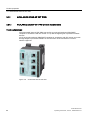
SCALANCE X-200
___________________
Preface
1
___________________
Safety notices
SIMATIC NET
Industrial Ethernet Switches
SCALANCE X-200
Network topologies / media
2
___________________
redundancy
3
___________________
Product properties
4
___________________
Installation
5
___________________
Connection
Operating Instructions
Configuration / diagnostics
6
___________________
using remote mechanisms
IRT technology with
7
___________________
SCALANCE X-200
8
___________________
PROFINET IO functionality
9
___________________
Approvals and markings
10
___________________
Technical specifications
11
___________________
Accessories
12
___________________
References
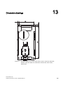
13
___________________
Dimension drawings
12/2011
A5E00349864-19
Legal information
Legal information
Warning notice system
This manual contains notices you have to observe in order to ensure your personal safety, as well as to prevent
damage to property. The notices referring to your personal safety are highlighted in the manual by a safety alert
symbol, notices referring only to property damage have no safety alert symbol. These notices shown below are
graded according to the degree of danger.
DANGER
indicates that death or severe personal injury will result if proper precautions are not taken.
WARNING
indicates that death or severe personal injury may result if proper precautions are not taken.
CAUTION
with a safety alert symbol, indicates that minor personal injury can result if proper precautions are not taken.
CAUTION
without a safety alert symbol, indicates that property damage can result if proper precautions are not taken.
NOTICE
indicates that an unintended result or situation can occur if the relevant information is not taken into account.
If more than one degree of danger is present, the warning notice representing the highest degree of danger will
be used. A notice warning of injury to persons with a safety alert symbol may also include a warning relating to
property damage.
Qualified Personnel
The product/system described in this documentation may be operated only by personnel qualified for the specific
task in accordance with the relevant documentation, in particular its warning notices and safety instructions.
Qualified personnel are those who, based on their training and experience, are capable of identifying risks and
avoiding potential hazards when working with these products/systems.
Proper use of Siemens products
Note the following:
WARNING
Siemens products may only be used for the applications described in the catalog and in the relevant technical
documentation. If products and components from other manufacturers are used, these must be recommended
or approved by Siemens. Proper transport, storage, installation, assembly, commissioning, operation and
maintenance are required to ensure that the products operate safely and without any problems. The permissible
ambient conditions must be complied with. The information in the relevant documentation must be observed.
Trademarks
All names identified by ® are registered trademarks of Siemens AG. The remaining trademarks in this publication
may be trademarks whose use by third parties for their own purposes could violate the rights of the owner.
Disclaimer of Liability
We have reviewed the contents of this publication to ensure consistency with the hardware and software
described. Since variance cannot be precluded entirely, we cannot guarantee full consistency. However, the
information in this publication is reviewed regularly and any necessary corrections are included in subsequent
editions.
Siemens AG
Industry Sector
Postfach 48 48
90026 NÜRNBERG
GERMANY
Order number: A5E00349864-19
Ⓟ 12/2011 Technical data subject to change
Copyright © Siemens AG 2011.
All rights reserved
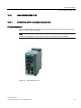
Preface
Overview of the SCALANCE X product family
The SCALANCE X-200 product family is part of the SCALANCE X product family. Below,
you will find a brief overview of this product family.
The SCALANCE X family comprises various product lines that complement each other and
that are carefully tuned to specific automation tasks.
SCALANCE X005 and XB000 line, entry level
Unmanaged switch with five twisted-pair ports and optical diagnostics on the device for use
in machine and system islands.
SCALANCE X-100 unmanaged
Switches with redundant power supply and signaling contact for use in applications in the
immediate vicinity of machinery.
A variety of device variants with different numbers and designs of electrical and optical ports.
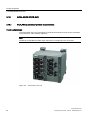
SCALANCE X-200 and XF-200 managed
The devices of the SCALANCE X-200 product line can be used universally – in machinelevel applications as well as in networked plant sections, in electrical or electrical/optical
linear, ring or star structures and with single mode up to 26 km.
Devices with a high degree of protection (IP65/67) can be installed outside the control
cabinet.
Configuration and remote diagnostics functions are integrated in the STEP 7 engineering
tool. This increases plant availability and has advantages during the engineering,
commissioning and operational phases. The devices of the SCALANCE X-200 line also have
standard remote diagnostics functions (SNMP, Web server).
The only difference between the devices of the SCALANCE XF-200 product line and the
SCALANCE X-200 product is the flatter construction.
SCALANCE X-200IRT and XF204IRT managed
In subsystem networks with hard real-time requirements (real time and isochronous real
time), the SCALANCE X-200IRT switches can be used. They include the enhanced real-time
controller ERTEC. By using the "cut through" switching mechanism, the switches are ideal to
meet the real-time requirements of PROFINET.
The standard data transmission (TCP/IP) can take place on the same network. Dual network
structures are therefore not necessary.
Network installation, configuration and diagnostics involves the same procedures as for the
other devices of the SCALANCE X-200 product line.
SCALANCE X-200
Operating Instructions, 12/2011, A5E00349864-19
3
Preface
The only difference between the SCALANCE XF204IRT and the SCALANCE X-204IRT is
the shape.
SCALANCE X-200 IRT PRO managed
In terms of functionality, the SCALANCE X200 IRT PRO switches are the same as the
SCALANCE X-200 IRT managed switches listed above. The switch with degree of protection
IP65/IP67 is designed for use outside a cabinet and has PROFINET-compliant connector
technology (RJ-45 in compliance with IEC 61076-3-117 for X204 IRT PRO or SC RJ in
compliance with IEC 61754-24-2 for X202-2P IRT PRO).
SCALANCE X-300
The main areas of application are high-speed plant networks with an interface to the
Enterprise network. The SCALANCE X-300 managed plus product line combines the
firmware functionality of the SCALANCE X-400 product line (without routing functions at the
layer 3 level) with the compact design of the SCALANCE X-200 product line. The "managed
plus" attribute means both enhanced management functions compared with the SCALANCE
X-200 and enhanced firmware functionality.
SCALANCE X-400 modular
The switches of the SCALANCE X-400 product series are suitable for the construction of
optical/electrical linear, ring and star topologies (10/100/1000 Mbps) for high-speed systems.
They have a modular structure, in which media modules and extender modules can be
inserted in the switch as required. These expansions make as many as eight electrical and
eight optical ports additionally available.
By supporting IT standards, for example, VLAN, RSTP, Layer 3, automation networks can be
seamlessly connected to existing corporate networks.
The SCALANCE X-400 switches are ideally suited, for example, for process control systems
such as PCS 7.
What is possible?
The devices of the SCALANCE X-200 product lines allow the cost-effective installation of
Industrial Ethernet linear (bus), star and ring structures with switching functionality.
By using the “cut through” switching mechanism, the SCALANCE X-200IRT switches are
ideal to meet the real-time requirements of PROFINET.
Cut through is not possible
● between a port set to 10 Mbps and a port set to 100 Mbps
● when two packets are to be sent at the same time on one port.
SCALANCE X-200
4
Operating Instructions, 12/2011, A5E00349864-19
Preface
One particular advantage of the SCALANCE X-200IRT switches in PROFINET networks is
the integrated ERTEC. This gives priority to PROFINET packets when forwarding.
WARNING
When used under hazardous conditions (zone 2), the devices of the SCALANCE X-100 and
SCALANCE X-200 product lines must be installed in an enclosure.
To comply with ATEX95 (EN 60079-15), this enclosure must meet the requirements of at
least IP54 in compliance with EN 60529.
WARNING – EXPLOSION HAZARD: DO NOT DISCONNECT EQUIPMENT WHEN A
FLAMMABLE OR COMBUSTIBLE ATMOSPHERE IS PRESENT.
Note
The specified approvals apply only when the corresponding mark is printed on the product.
Purpose of the Operating Instructions
These operating instructions support you when commissioning networks with the devices of
the product line SCALANCE X-200.
Validity of the Operating Instructions
These operating instructions are valid for the following devices:
SIMATIC NET SCALANCE XF204
6GK5204-0BA00-2AF2
SIMATIC NET SCALANCE X208
6GK5208-0BA10-2AA3
SIMATIC NET SCALANCE XF208
6GK5208-0BA00-2AF2
SIMATIC NET SCALANCE X216
6GK5216-0BA00-2AA3
SIMATIC NET SCALANCE X224
6GK5224-0BA00-2AA3
SIMATIC NET SCALANCE X204-2
6GK5204-2BB10-2AA3
SIMATIC NET SCALANCE X204-2TS
6GK5204-2BB10-2CA2
SIMATIC NET SCALANCE XF204-2
6GK5204-2BC00-2AF2
SIMATIC NET SCALANCE X206-1
6GK5206-1BB10-2AA3
SIMATIC NET SCALANCE XF206-1
6GK5206-1BC00-2AF2
SIMATIC NET SCALANCE X212-2
6GK5212-2BB00-2AA3
SIMATIC NET SCALANCE X204-2LD
6GK5204-2BC10-2AA3
SIMATIC NET SCALANCE X206-1LD
6GK5206-1BC10-2AA3
SIMATIC NET SCALANCE X212-2LD
6GK5212-2BC00-2AA3
SIMATIC NET SCALANCE X202-2IRT
6GK5202-2BB00-2BA3
SIMATIC NET SCALANCE X204IRT
6GK5204-0BA00-2BA3
SIMATIC NET SCALANCE XF204IRT
6GK5204-0BA00-2BF2
SIMATIC NET SCALANCE X204 IRT PRO
6GK5204-0JA00-2BA6
SIMATIC NET SCALANCE X202-2P IRT PRO
6GK5202-2JR00-2BA6
SCALANCE X-200
Operating Instructions, 12/2011, A5E00349864-19
5
Preface
SIMATIC NET SCALANCE X201-3P IRT PRO
6GK5201-3JR00-2BA6
SIMATIC NET SCALANCE X202-2P IRT
6GK5202-2BH00-2BA3
SIMATIC NET SCALANCE X201-3P IRT
6GK5201-3BH00-2BA3
SIMATIC NET SCALANCE X200-4P IRT
6GK5200-4AH00-2BA3
Names of the devices in these operating instructions
The descriptions in these operating instructions always apply to the devices of the
SCALANCE X-200 product line listed under "Validity of the Operating Instructions" in this
document unless the description relates to a specific device of the product line. In the
remainder of the description, the devices are called IE Switch X-200 or X-200 IE switches.
Further documentation
The "SIMATIC NET Industrial Ethernet Twisted Pair and Fiber Optic Networks" manual
contains additional information on other SIMATIC NET products that you can operate along
with the devices of the SCALANCE X-200 product line in an Industrial Ethernet network.
Finding information
To help you to find the information you require more quickly, the manual includes not only
the table of contents but also the following sections in the Appendix:
● Index
● Glossary
Audience
These operating instructions are intended for persons involved in commissioning networks in
which IE switches are used.
Standards and approvals
The devices of the SCALANCE X-200 product line meet the requirements for the CE mark.
You will find detailed information in the section "Approvals and markings" in these operating
instructions.
SIMATIC NET glossary
Explanations of the specialist terms used in this documentation can be found in the SIMATIC
NET glossary.
You will find the SIMATIC NET glossary here:
● SIMATIC NET Manual DVD
The DVD ships with most SIMATIC NET products.
● On the Internet under the following entry ID:
50305045 (http://support.automation.siemens.com/WW/view/en/50305045)
SCALANCE X-200
6
Operating Instructions, 12/2011, A5E00349864-19
Table of contents
Preface ...................................................................................................................................................... 3
1
Safety notices .......................................................................................................................................... 13
1.1
2
3
Important notes on using the device............................................................................................13
Network topologies / media redundancy .................................................................................................. 17
2.1
Network topologies ......................................................................................................................17
2.2
Options of media redundancy ......................................................................................................22
2.3
Media redundancy in ring topologies ...........................................................................................23
2.4
MRP .............................................................................................................................................25
2.5
MRPD...........................................................................................................................................27
2.6
HSR..............................................................................................................................................28
2.7
Redundant coupling of network segments...................................................................................29
Product properties ................................................................................................................................... 31
3.1
Overview of the product characteristics.......................................................................................31
3.2
Components of the product..........................................................................................................33
3.3
Unpacking and checking..............................................................................................................34
3.4
3.4.1
3.4.2
SCALANCE XF204 ......................................................................................................................35
SCALANCE XF204 product characteristics.................................................................................35
SCALANCE XF204 TP ports .......................................................................................................36
3.5
3.5.1
3.5.2
SCALANCE X208 ........................................................................................................................38
SCALANCE X208 product characteristics ...................................................................................38
SCALANCE X208 TP ports..........................................................................................................39
3.6
3.6.1
3.6.2
SCALANCE XF208 ......................................................................................................................41
SCALANCE XF208 product characteristics.................................................................................41
SCALANCE XF208 TP ports .......................................................................................................42
3.7
3.7.1
3.7.2
SCALANCE X216 ........................................................................................................................44
SCALANCE X216 product characteristics ...................................................................................44
SCALANCE X216 TP ports..........................................................................................................45
3.8
3.8.1
3.8.2
SCALANCE X224 ........................................................................................................................47
SCALANCE X224 product characteristics ...................................................................................47
SCALANCE X224 TP ports..........................................................................................................48
3.9
3.9.1
3.9.2
3.9.3
SCALANCE X204-2 / SCALANCE X204-2TS .............................................................................50
SCALANCE X204-2 / SCALANCE X204-2TS product features ..................................................50
SCALANCE X204-2 / SCALANCE X204-2TS TP interfaces.......................................................51
SCALANCE X204-2 / SCALANCE X204-2TS FO interfaces ......................................................53
3.10
3.10.1
SCALANCE XF204-2...................................................................................................................54
SCALANCE XF204-2 product characteristics..............................................................................54
SCALANCE X-200
Operating Instructions, 12/2011, A5E00349864-19
7
Table of contents
3.10.2
3.10.3
SCALANCE XF204-2 TP ports ................................................................................................... 55
SCALANCE XF204-2 FO ports................................................................................................... 57
3.11
3.11.1
3.11.2
3.11.3
SCALANCE X206-1 .................................................................................................................... 58
SCALANCE X206-1 product characteristics ............................................................................... 58
SCALANCE X206-1 TP ports ..................................................................................................... 59
SCALANCE X206-1 FO ports ..................................................................................................... 61
3.12
3.12.1
3.12.2
3.12.3
SCALANCE XF206-1 .................................................................................................................. 62
SCALANCE XF206-1 product characteristics............................................................................. 62
SCALANCE XF206-1 TP ports ................................................................................................... 63
SCALANCE XF206-1 FO ports................................................................................................... 65
3.13
3.13.1
3.13.2
3.13.3
SCALANCE X212-2 .................................................................................................................... 66
SCALANCE X212-2 product characteristics ............................................................................... 66
SCALANCE X212-2 TP ports ..................................................................................................... 67
SCALANCE X212-2 FO ports ..................................................................................................... 69
3.14
3.14.1
3.14.2
3.14.3
SCALANCE X204-2LD................................................................................................................ 70
SCALANCE X204-2LD product characteristics .......................................................................... 70
SCALANCE X204-2LD TP ports................................................................................................. 71
SCALANCE X204-2LD TP ports................................................................................................. 73
3.15
3.15.1
3.15.2
3.15.3
SCALANCE X206-1LD................................................................................................................ 75
SCALANCE X206-1LD product characteristics .......................................................................... 75
SCALANCE X206-1LD TP ports................................................................................................. 76
SCALANCE X206-1LD FO ports ................................................................................................ 78
3.16
3.16.1
3.16.2
3.16.3
SCALANCE X212-2LD................................................................................................................ 80
SCALANCE X212-2LD product characteristics .......................................................................... 80
SCALANCE X212-2LD TP ports................................................................................................. 81
SCALANCE X212-2LD FO ports ................................................................................................ 83
3.17
3.17.1
3.17.2
3.17.3
SCALANCE X202-2IRT .............................................................................................................. 85
SCALANCE X202-2IRT product characteristics ......................................................................... 85
SCALANCE X202-2IRT TP ports................................................................................................ 86
SCALANCE X202-2IRT FO ports ............................................................................................... 88
3.18
3.18.1
3.18.2
SCALANCE X204IRT.................................................................................................................. 89
SCALANCE X204IRT product characteristics ............................................................................ 89
SCALANCE X204IRT TP ports................................................................................................... 90
3.19
3.19.1
3.19.2
SCALANCE XF204IRT ............................................................................................................... 92
SCALANCE XF204IRT product characteristics .......................................................................... 92
SCALANCE XF204IRT TP ports................................................................................................. 93
3.20
3.20.1
3.20.2
SCALANCE X204 IRT PRO........................................................................................................ 95
SCALANCE X204 IRT PRO product characteristics .................................................................. 95
SCALANCE X204 IRT PRO TP ports ......................................................................................... 96
3.21
3.21.1
3.21.2
3.21.3
SCALANCE X202-2P IRT PRO .................................................................................................. 98
SCALANCE X202-2P IRT PRO product characteristics............................................................. 98
SCALANCE X202-2P IRT PRO TP ports ................................................................................... 99
SCALANCE X202-2P IRT PRO FO ports ................................................................................. 101
3.22
3.22.1
3.22.2
SCALANCE X201-3P IRT PRO ................................................................................................ 102
SCALANCE X201-3P IRT PRO product characteristics........................................................... 102
SCALANCE X201-3P IRT PRO TP interfaces.......................................................................... 103
SCALANCE X-200
8
Operating Instructions, 12/2011, A5E00349864-19
Table of contents
4
5
6
3.22.3
SCALANCE X201-3P IRT PRO FO interfaces ..........................................................................105
3.23
3.23.1
3.23.2
3.23.3
SCALANCE X202-2P IRT..........................................................................................................106
SCALANCE X202-2P IRT product characteristics.....................................................................106
SCALANCE X202-2P IRT TP ports ...........................................................................................107
SCALANCE X202-2P IRT FO ports...........................................................................................109
3.24
3.24.1
3.24.2
3.24.3
SCALANCE X201-3P IRT..........................................................................................................110
SCALANCE X201-3P IRT product characteristics.....................................................................110
SCALANCE X201-3P IRT TP ports ...........................................................................................111
SCALANCE X201-3P IRT FO ports...........................................................................................113
3.25
3.25.1
3.25.2
SCALANCE X200-4P IRT..........................................................................................................114
SCALANCE X200-4P IRT product characteristics.....................................................................114
SCALANCE X200-4P IRT FO ports...........................................................................................115
3.26
C-PLUG (configuration plug)......................................................................................................116
3.27
Button.........................................................................................................................................119
3.28
3.28.1
3.28.2
3.28.3
3.28.4
3.28.5
3.28.6
3.28.7
Displays......................................................................................................................................120
Fault indicator (red LED)............................................................................................................120
Power display.............................................................................................................................121
Port status indicator (green/yellow LEDs)..................................................................................123
Redundancy manager indicator (green LED) ............................................................................124
Standby functions (yellow LED) .................................................................................................125
FOC diagnostic display (yellow LED) ........................................................................................126
LED display during startup.........................................................................................................127
Installation ............................................................................................................................................. 129
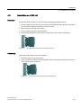
4.1
Installation ..................................................................................................................................129
4.2
Installation on a DIN rail.............................................................................................................131
4.3
Installation on a standard rail .....................................................................................................132
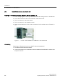
4.4
Wall mounting ............................................................................................................................133
Connection ............................................................................................................................................ 135
5.1
Power supply..............................................................................................................................135
5.2
Signaling contact........................................................................................................................140
5.3
Grounding ..................................................................................................................................142
5.4
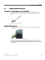
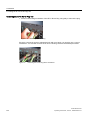
Fitting the IE FC RJ-45 Plug 180 ...............................................................................................143
5.5
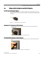
Fitting the IE RJ 45 Plug Pro and IE SC RJ Plug Pro................................................................145
Configuration / diagnostics using remote mechanisms .......................................................................... 147
6.1
6.1.1
6.1.2
6.1.2.1
6.1.2.2
6.1.2.3
6.1.2.4
6.1.2.5
6.1.2.6
Assignment of an IP address .....................................................................................................147
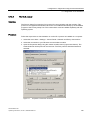
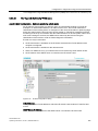
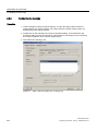
Introduction ................................................................................................................................147
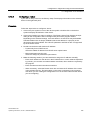
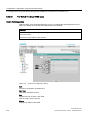
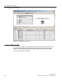
Configuration with the Primary Setup Tool ................................................................................147
Configuration with the Primary Setup Tool ................................................................................147
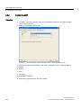
Installing the Primary Setup Tool ...............................................................................................148
The DLC protocol.......................................................................................................................149
Installing the DLC protocol.........................................................................................................150
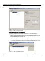
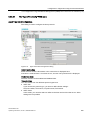
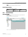
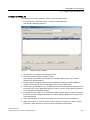
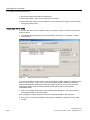
Working with the Primary Setup Tool ........................................................................................150
Configuring a module.................................................................................................................151
SCALANCE X-200
Operating Instructions, 12/2011, A5E00349864-19
9
Table of contents
7
6.1.3
Configuration with DHCP .......................................................................................................... 154
6.2
Updating the firmware with the boot loader .............................................................................. 155
6.3
6.3.1
6.3.2
6.3.3
6.3.4
6.3.5
6.3.5.1
6.3.5.2
6.3.5.3
6.3.5.4
6.3.5.5
6.3.5.6
6.3.5.7
6.3.5.8
6.3.5.9
6.3.5.10
6.3.5.11
6.3.5.12
6.3.5.13
6.3.5.14
6.3.5.15
6.3.5.16
6.3.5.17
6.3.5.18
6.3.5.19
6.3.5.20
6.3.5.21
6.3.5.22
6.3.5.23
6.3.5.24
6.3.5.25
6.3.5.26
6.3.5.27
6.3.5.28
6.3.5.29
6.3.5.30
6.3.5.31
6.3.5.32
6.3.5.33
6.3.5.34
6.3.5.35
6.3.5.36
6.3.5.37
6.3.5.38
6.3.5.39
6.3.6
6.3.6.1
6.3.6.2
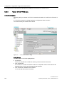
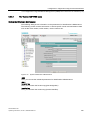
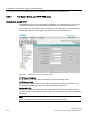
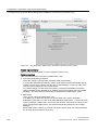
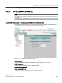
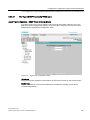
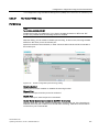
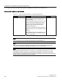
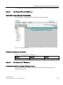
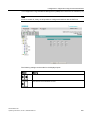
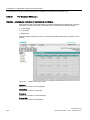
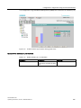
Configuration using Web Based Management (WBM) and Command Line Interface (CLI) .... 156
Principle of Web Based Management....................................................................................... 157
LED simulation .......................................................................................................................... 159
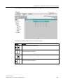
Working with WBM.................................................................................................................... 159
Command Line Interface (CLI).................................................................................................. 161
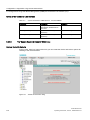
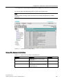
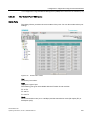
WBM menus.............................................................................................................................. 163
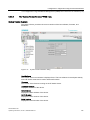
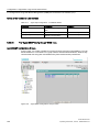
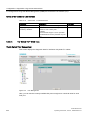
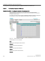
Management menus - the Start menu ...................................................................................... 163
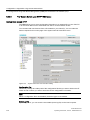
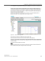
The "System" WBM menu......................................................................................................... 164
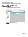
"System C-PLUG" WBM menu ................................................................................................. 166
The "System I&M" WBM menu ................................................................................................. 169
The "System Restart & Defaults" WBM menu .......................................................................... 170
The "System Save & Load HTTP" WBM menu ........................................................................ 172
The "System Save & Load TFTP" WBM menu......................................................................... 174
The "System Version Numbers" WBM menu............................................................................ 177
The "System Passwords" WBM menu...................................................................................... 179
The "System Select/Set Button" WBM menu............................................................................ 180
The "System Event Log" WBM menu ....................................................................................... 180
The "X200" WBM menu ............................................................................................................ 182
The "X200 Fault Mask" WBM menu ......................................................................................... 183
The "X200 Ring" WBM menu.................................................................................................... 185
The "X200 Standby" WBM menu .............................................................................................. 190
The "Agent" WBM menu ........................................................................................................... 192
The "Ping" WBM menu ............................................................................................................. 194
The "Agent SNMP Config" WBM menu .................................................................................... 195
The "Agent SNMP Trap Config" WBM menu............................................................................ 197
The "Agent SNMP Config Groups" WBM menu ....................................................................... 198
The "Agent SNMP Config Group Table" WBM menu ............................................................... 200
The "Agent SNMP Config Users" WBM menu.......................................................................... 202
The "Agent SNMP Config User Table" WBM menu.................................................................. 203
The "Agent Event Config" WBM menu ..................................................................................... 204
The "Agent E-Mail Config" WBM menu .................................................................................... 207
The "Agent Time Config" WBM menu....................................................................................... 209
The "Switch" WBM menu .......................................................................................................... 211
The "Switch Ports" WBM menu................................................................................................. 213
The "Switch Port Diags" WBM menu ........................................................................................ 216
The "Switch FDB" WBM menu.................................................................................................. 217
The "Switch ARP Table" WBM menu ....................................................................................... 219
The "Switch LLDP" WBM menu ................................................................................................ 219
The "Switch DCP" WBM menu ................................................................................................. 222
The "Switch POF" WBM menu.................................................................................................. 224
The "Loop Detection Config" WBM menu................................................................................. 226
The "Statistics" WBM menu ...................................................................................................... 230
The "Statistics Packet Size" WBM menu .................................................................................. 232
The "Statistics Packet Type" WBM menu ................................................................................. 234
The "Statistics Packet Error" WBM menu ................................................................................. 236
SNMP ........................................................................................................................................ 238
Configuration and diagnostics over SNMP ............................................................................... 238
MIB variables ............................................................................................................................ 239
IRT technology with SCALANCE X-200................................................................................................. 243
SCALANCE X-200
10
Operating Instructions, 12/2011, A5E00349864-19
Table of contents
8
PROFINET IO functionality .................................................................................................................... 245
8.1
Configuring with PROFINET IO .................................................................................................245
8.2
8.2.1
8.2.2
8.2.3
Settings in HW Config................................................................................................................249
Configuring alarms.....................................................................................................................249
Configuring MRP........................................................................................................................250
Configuring the topology ............................................................................................................254
8.3
HSR configuration in PROFINET IO ..........................................................................................256
8.4
Structure of the data records .....................................................................................................257
9
Approvals and markings ........................................................................................................................ 263
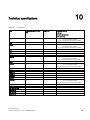
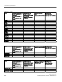
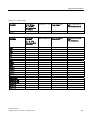
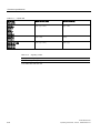
10
Technical specifications......................................................................................................................... 275
11
Accessories ........................................................................................................................................... 285
12
References ............................................................................................................................................ 287
13
Dimension drawings .............................................................................................................................. 289
Index...................................................................................................................................................... 295
SCALANCE X-200
Operating Instructions, 12/2011, A5E00349864-19
11
Table of contents
SCALANCE X-200
12
Operating Instructions, 12/2011, A5E00349864-19
Safety notices
1.1
1
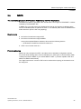
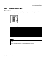
Important notes on using the device
Safety notices on the use of the devices
The following safety notices must be adhered to when setting up and operating the device
and during all work relating to it such as installation, connecting up, replacing devices or
opening the device.
General notices
WARNING
Safety extra low voltage
The equipment is designed for operation with Safety Extra-Low Voltage (SELV) by a
Limited Power Source (LPS). (This does not apply to 100 V...240 V devices.)
This means that only SELV / LPS complying with IEC 60950-1 / EN 60950-1 / VDE 0805-1
must be connected to the power supply terminals. The power supply unit for the equipment
power supply must comply with NEC Class 2, as described by the National Electrical Code
(r) (ANSI / NFPA 70).
There is an additional requirement if devices are operated with a redundant power supply:
If the equipment is connected to a redundant power supply (two separate power supplies),
both must meet these requirements.
WARNING
Opening the device
DO NOT OPEN WHEN ENERGIZED.
General notices on use in hazardous areas
WARNING
Risk of explosion when connecting or disconnecting the device
EXPLOSION HAZARD
DO NOT CONNECT OR DISCONNECT EQUIPMENT WHEN A FLAMMABLE OR
COMBUSTIBLE ATMOSPHERE IS PRESENT.
SCALANCE X-200
Operating Instructions, 12/2011, A5E00349864-19
13
Safety notices
1.1 Important notes on using the device
WARNING
Replacing components
EXPLOSION HAZARD
SUBSTITUTION OF COMPONENTS MAY IMPAIR SUITABILITY FOR CLASS I, DIVISION
2 OR ZONE 2.
WARNING
Requirements for the cabinet/enclosure
When used in hazardous environments corresponding to Class I, Division 2 or Class I,
Zone 2, the device must be installed in a cabinet or a suitable enclosure.
WARNING
WARNING - EXPLOSION HAZARD DO NOT DISCONNECT WHILE CIRCUIT IS LIVE UNLESS AREA IS KNOWN TO BE
NON-HAZARDOUS.
WARNING
Restricted area of application
This equipment is suitable for use in Class I, Division 2, Groups A, B, C and D or nonhazardous locations only.
WARNING
Restricted area of application
This equipment is suitable for use in Class I, Zone 2, Group IIC or non-hazardous locations
only.
General notices on use in hazardous areas according to ATEX
WARNING
Requirements for the cabinet/enclosure
To comply with EU Directive 94/9 (ATEX95), this enclosure must meet the requirements of
at least IP54 in compliance with EN 60529.
The fiber-optic bus connections labeled SCALANCE X-200/XF-200 (see type plate) may
also be led through a hazardous area zone1 (see also Approvals and markings (Page 263),
section "Explosion Protection Directive (ATEX)").
SCALANCE X-200
14
Operating Instructions, 12/2011, A5E00349864-19
Safety notices
1.1 Important notes on using the device
WARNING
Suitable cables for temperatures in excess of 70 °C
If the cable or conduit entry point exceeds 70 °C or the branching point of conductors
exceeds 80 °C, special precautions must be taken. If the equipment is operated in an air
ambient in excess of 50 °C to 70 °C, only use cables with admitted maximum operating
temperature of at least 80 °C.
WARNING
Protection against transient voltage surges
Provisions shall be made to prevent the rated voltage from being exceeded by transient
voltage surges of more than 40%. This criterion is fulfilled, if supplies are derived from
SELV (Safety Extra-Low Voltage) only.
See also
Approvals and markings (Page 263)
SCALANCE X-200
Operating Instructions, 12/2011, A5E00349864-19
15
Safety notices
1.1 Important notes on using the device
SCALANCE X-200
16
Operating Instructions, 12/2011, A5E00349864-19
Network topologies / media redundancy
2.1
2
Network topologies
Switching technology allows extensive networks to be set up with numerous nodes and
simplifies network expansion.
Which topologies can be implemented?
Bus, ring, or star topologies can be implemented with the X-200 IE switches.
Note
Make sure that the maximum permitted cable lengths for the relevant devices are not
exceeded. You will find the permitted cable lengths in the technical specifications.
For example, with the SCALANCE X202-2P IRT, X201-3P IRT, X200P IRT, X202-2P IRT
PRO and X201-3P IRT PRO only 50 m POF or 100 m HCS cable may be used.
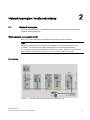
Bus topology
Figure 2-1
Electrical / optical linear topology with SCALANCE X-100
SCALANCE X-200
Operating Instructions, 12/2011, A5E00349864-19
17
Network topologies / media redundancy
2.1 Network topologies
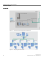
Star topology
Figure 2-2
Electrical star topology. Example with SCALANCE X208
Figure 2-3
Star topology with X310 and X208
SCALANCE X-200
18
Operating Instructions, 12/2011, A5E00349864-19
Network topologies / media redundancy
2.1 Network topologies
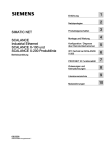
Ring topology
Figure 2-4
Optical ring topology, example with SCALANCE X-200 and SCALANCE X-400 as
redundancy manager
SCALANCE X-200
Operating Instructions, 12/2011, A5E00349864-19
19
Network topologies / media redundancy
2.1 Network topologies
PC
Operator Station
S7-400
S7-400
Switch
SCALANCE
X-400
PC
S7-300
Twisted Pair
S7-400
Switch
SCALANCE
X208
S7-300
PC
PC
S7-400
S7-300
S7-400
PC
S7-400
G_IK10_XX_10101
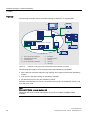
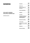
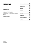
Figure 2-5
Electrical ring topology, example with SCALANCE X208 and SCALANCE X-400 as
redundancy manager
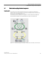
Figure 2-6
Ring topology with electrical and optical ring links, example with SCALANCE X206-1,
SCALANCE X208, and SCALANCE X204-2 as redundancy manager
SCALANCE X-200
20
Operating Instructions, 12/2011, A5E00349864-19
Network topologies / media redundancy
2.1 Network topologies
Figure 2-7
Ring topology with optical ring, example with SCALANCE X202-2IRT
To increase availability, optical or electrical bus topologies made up of X-200 IE Switches
with an IE Switch X-200, IE Switch X-300, SCALANCE X414-3E, OSM version 2 or ESM
version 2 configured as a redundancy manager can be closed to form a ring. The
IE Switches X-200 are first connected over their ring ports to form a bus. The two ends of the
bus are closed to form a ring by a switch operating in the redundancy manager mode.
Devices of the IE switches X-200, X-300, X-400 product families, or OSMs / ESMs can be
used as the redundancy manager. When a switch is used as the redundancy manager, the
ring ports are isolated from each other if the network is operating problem-free.
The IE Switch X-200, IE Switch X-300, SCALANCE X414-3E, or OSM / ESM operating in the
redundancy manager mode monitors the connected bus over its ring ports and switches the
ring ports through if there is an interruption on the connected bus; in other words, it restores
a functioning bus over this substitute path. Reconfiguration takes place within 0.3 seconds.
As soon as the problem has been eliminated, the original topology is restored; in other
words, the ring ports in the redundancy manager are once again disconnected from each
other.
SCALANCE X-200
Operating Instructions, 12/2011, A5E00349864-19
21
Network topologies / media redundancy
2.2 Options of media redundancy
2.2
Options of media redundancy
There are various options available to increase the network availability of an Industrial
Ethernet network with optical or electrical linear bus topologies:
● Mesh networks
● Parallel connection of transmission paths
● Closing a linear bus topology to form a ring topology
SCALANCE X-200
22
Operating Instructions, 12/2011, A5E00349864-19
Network topologies / media redundancy
2.3 Media redundancy in ring topologies
2.3
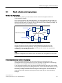
Media redundancy in ring topologies
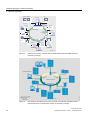
Structure of a ring topology
Nodes in a ring topology can be external switches and/or the integrated switches of
communications modules.
To set up a ring topology with media redundancy, you bring together the two free ends of a
linear bus topology in one device. Closing the linear bus topology to form a ring is achieved
with two ports (ring ports) of a device in the ring. This device is the redundancy manager. All
other devices in the ring are redundancy clients.
7HVWIUDPHV
5HGXQGDQF\PDQDJHU
5HGXQGDQF\FOLHQWV
7HVWIUDPHV
Figure 2-8
Devices in a ring topology with media redundancy
The two ring ports of a device are the ports that establish the connection to its two
neighboring devices in the ring topology. The ring ports are selected and set in the
configuration of the relevant device. On the S7 Ethernet CP modules, the ring ports are
indicated by an "R" after the port number.
Note
Create the configuration of the devices to be connected to form a ring before you close the
ring.
How media redundancy works in a ring topology
When using media redundancy, the data paths between the individual devices are
reconfigured if the ring is interrupted at one point. Following reconfiguration of the topology,
the devices can once again be reached in the resulting new topology.
In the redundancy manager, the 2 ring ports are disconnected from each other if the network
is uninterrupted. This prevents circulating data frames. In terms of data transmission, the ring
topology is a linear bus topology. The redundancy manager monitors the ring topology. It
does this by sending test frames both from ring port 1 and ring port 2. The test frames run
round the ring in both directions until they arrive at the other ring port of the redundancy
manager.
SCALANCE X-200
Operating Instructions, 12/2011, A5E00349864-19
23
Network topologies / media redundancy
2.3 Media redundancy in ring topologies
An interruption of the ring can be caused by loss of the connection between two devices or
by failure of a device in the ring.
If the test frames of the redundancy manager no longer arrive at the other ring port, the
redundancy manager connects its two ring ports. This substitute path once again restores a
functioning connection between all remaining devices in the form of a linear bus topology.
The time between the ring interruption and restoration of a functional linear topology is
known as the reconfiguration time.
As soon as the interruption is eliminated, the original transmission paths are established
again, the two ring ports of the redundancy manager are disconnected and the redundancy
clients informed of the change. The redundancy clients then use the new paths to the other
devices.
If the redundancy manager fails, the ring becomes a functional linear bus.
Media redundancy methods
The following media redundancy methods are supported by SIMATIC NET products for ring
topologies:
● HSR (High Speed Redundancy)
Reconfiguration time: 0.3 seconds
● MRP (Media Redundancy Protocol)
Reconfiguration time: 0.2 seconds
Automatic configuration of the ring
The mechanisms of these methods are similar. With both methods, up to 50 devices can
participate in the ring. HSR and MRP cannot be used in the ring at the same time.
If you configure your plant using STEP 7, you can only select MRP as the media redundancy
method.
If you configure your devices with Web Based Management, CLI or SNMP, you can choose
either HSR or MRP.
Media redundancy with IRT
For ring topologies in which MRP is activated, the "MRPD" function is activated automatically
for IRT devices capable of IRT, if this is supported by the device.
● MRPD (Media Redundancy with Path Duplication)
For use only with SCALANCE X-200IRT
This procedure allows redundancy with IRT. You will find details in the section MRPD
(Page 27).
SCALANCE X-200
24
Operating Instructions, 12/2011, A5E00349864-19
Network topologies / media redundancy
2.4 MRP
2.4
MRP
The "MRP" method conforms to the Media Redundancy Protocol (MRP) specified in the
standard IEC 62439-2 Edition 1.0 2010-02.
The reconfiguration time after an interruption of the ring is a maximum of 0.2 seconds.
Requirements
The following requirements must be met for problem-free operation with the MRP media
redundancy protocol:
● MRP is supported in ring topologies with up to 50 devices. Exceeding this number of
devices can lead to a loss of data traffic.
● The ring in which you want to use MRP may only consist of devices that support this
function. This applies, for example, to the following devices:
– Industrial Ethernet switches
SCALANCE X-200 as of firmware version V4.0
SCALANCE X-200 IRT as of firmware version V4.0
SCALANCE X-300 as of firmware version V3.0
SCALANCE X-400 as of firmware version V3.0
– Communications processors
CP 443-1 Advanced (6GK7 443-1GX20-0XE0) as of firmware version V2.0
CP 343-1 Advanced (6GK7 343-1GX30-0XE0) as of firmware version V1.0
CP 1616 (6GK1 161-6AA00) as of firmware version V2.2
CP 1604 (6GK1 160-4AA00) as of firmware version V2.2
– Non-Siemens devices that support this functionality.
Further Siemens devices are planned that will support MRP.
● All devices must be interconnected via their ring ports.
● If you configure in STEP 7, MRP must be enabled on all devices in the ring (see "MRP
configuration in PROFINET IO").
● If you configure with Web Based Management, CLI or SNMP, set all the devices in the
ring to "MRP Client" or "Automatic Redundancy Detection". At least one device in the ring
must have the setting "Automatic Redundancy Detection".
In their basic status, the "Automatic Redundancy Detection" mode is set on IE switches
as default.
● The connection settings (transmission medium / duplex) must be set to full duplex and at
least 100 Mbps for all ring ports. Otherwise there may be a loss of data traffic.
– To do this, set all the ports involved in the ring to "Automatic settings" in the "Options"
tab of the properties dialog during STEP 7 configuration.
– If you configure with Web Based Management, the ring ports are set automatically to
autonegotiation.
SCALANCE X-200
Operating Instructions, 12/2011, A5E00349864-19
25
Network topologies / media redundancy
2.4 MRP
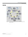
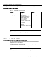
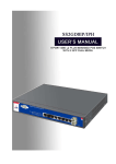
Topology
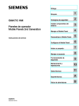
The following schematic shows a possible topology for devices in a ring with MRP.
7
6
8
1
2
3
5HGXQGDQF\GRPDLQ
5
9
4
10
6ZLWK&3$GYDQFHG
+0,VWDWLRQ
6&$/$1&(;VZLWFK
(QJLQHHULQJVWDWLRQ
3&ZLWK&3
(76
6ZLWK&3$GYDQFHG
(70
(7SUR
Figure 2-9
Example of a ring topology with the MRP media redundancy protocol
The following rules apply to a ring topology with media redundancy using MRP:
● All the devices connected within the ring topology are members of the same redundancy
domain.
● One device in the ring is acting as redundancy manager.
● All other devices in the ring are redundancy clients.
Non MRP-compliant devices can be connected to the ring via a SCALANCE X switch or via
a PC with a CP 1616.
Note
SCALANCE X-300 - modular devices (M)
Remember that in the modular switches the ring ports are located on MM900 media
modules.
SCALANCE X-200
26
Operating Instructions, 12/2011, A5E00349864-19
Network topologies / media redundancy
2.5 MRPD
2.5
MRPD
The redundancy procedure MRPD (Media Redundancy with Path Duplication)
The MRPD procedure is specified in IEC 61158 Parts 5 and 6 type 10 "PROFINET". It allows
redundancy for PROFINET IRT.
In MRPD, the cyclic IRT frames are duplicated and sent to the recipient via different paths.
The two redundant paths are planned in STEP 7. Two different paths are then available if the
entire network or part of it has a ring topology.
Requirements
● All devices involved must support IRT.
● All devices involved must support MRPD.
Among the Industrial Ethernet switches, this means the following devices:
– SCALANCE X-200IRT as of firmware version 5.0
● STEP 7 as of version V5.5 SP1
Project engineering
MRPD can only configured in STEP 7 and there are no alternative configuration options.
To prevent loops forming and to ensure redundancy for other types of communication, MRP
is always required for MRPD. If you activate MRP in STEP 7, products capable of IRT and
MRPD use MRPD automatically.
The "High Performance" version of IRT must be used and the topology of the network must
be configured.
SCALANCE X-200
Operating Instructions, 12/2011, A5E00349864-19
27
Network topologies / media redundancy
2.6 HSR
2.6
HSR
The "HSR" method allows a reconfiguration time of 0.3 seconds following an interruption in
the ring.
Requirements
The following requirements must be met for problem-free operation with the HSR media
redundancy method:
● HSR is supported in ring topologies with up to 50 devices. Exceeding this number of
devices can lead to a loss of data traffic.
● The ring in which you want to use HSR may only consist of devices that support this
function. This applies, for example, to the following devices: X-400 IE switches, X-300
IE switches, X-200 IE switches and OSM / ESM.
● All devices must be interconnected via their ring ports.
● A device in the ring must be configured as redundancy manager by selecting the "HSR
Manager" setting. You can do this with the button on the front of the device, Web Based
Management, CLI or SNMP.
● On all other devices in the ring, either the "HSR Client" or "Automatic Redundancy
Detection" mode must be activated.
You can do this with Web Based Management, CLI or SNMP.
● In the basic status, the "HSR Client" or "Automatic Redundancy Detection" mode is set as
default.
SCALANCE X-200
28
Operating Instructions, 12/2011, A5E00349864-19
Network topologies / media redundancy
2.7 Redundant coupling of network segments
2.7
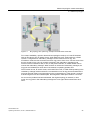
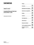
Redundant coupling of network segments
Coupling option
The coupling of two network segments shown here as an example is possible with X200IRT, X-300 and X-400 IE switches. This requires the standby function of these devices
that can be set via the WEB interface or CLI.
If the standby function is enabled, this is signaled on X-200 IE switches by the RM-LED.
The SCALANCE X-200IRT can be operated either as an RM or in standby mode.
Figure 2-10
Redundant coupling of SCALANCE X-200 rings with 2 SCALANCE X-200 IRT devices
SCALANCE X-200
Operating Instructions, 12/2011, A5E00349864-19
29
Network topologies / media redundancy
2.7 Redundant coupling of network segments
SCALANCE X-200
30
Operating Instructions, 12/2011, A5E00349864-19
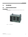
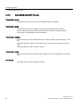
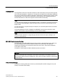
3
Product properties
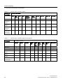
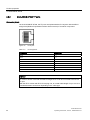
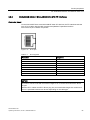
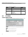
3.1
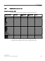
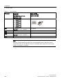
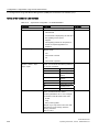
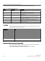
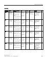
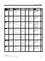
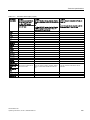
Table 3- 1
Overview of the product characteristics
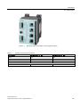
Overview of the product characteristics
Device type SCALANCE
XF204
X208
XF208
X216
X224,
X204-2
X204-2TS
XF204-2
X206-1
XF206-1,
X212-2
X204-2LD
X206-1LD
X212-2LD
X202-2 IRT
X204IRT
XF204 IRT
X204 IRT PRO
X202-2P IRT PRO
X201-3P IRT PRO
X202-2P IRT
X201-3P IRT
X200-4P IRT
X202-2 IRT
X204IRT
SIMATIC environment
●
●
Diagnostics LED
●
●
24 VDC
●
●
Compact housing (securing collar, etc.)
●
●
2x 24 V DC
●
●
Signaling contact + on-site operation
●
●
Diagnostics: Web, SNMP, PROFINET
●
●
C-PLUG
●
●
IRT capability
-
●
Fast learning
-
●
Passive listening
●
●
SNTP + SICLOCK
●
●
Cut through
-
●
Use in ring possible (as node and RM)
●
●
Standby manager
-
●
Note
IRT switches cannot be redundancy and standby manager at the same time.
Fast learning:
Fast recognition of MAC addresses on the device that change during operation (for example,
when an end node is reconnected).
SCALANCE X-200
Operating Instructions, 12/2011, A5E00349864-19
31
Product properties
3.1 Overview of the product characteristics
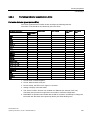
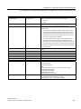
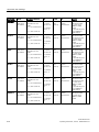
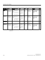
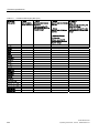
Table 3- 2
Overview of the connection options
Fast Ethernet
Device type SCALANCE
10/100 Mbps
XF204
X208
XF208
X216
X224
TP (RJ-45)
4
Fiber
multimode
(BFOC)
8
16
24
4
6
12
4
6
12
-
-
-
-
2
1
2
-
-
-
Fiber
single mode
(BFOC)
-
-
-
-
-
-
-
2
1
2
Fiber
POF / PCF
(SC-RJ)
-
-
-
-
-
-
-
-
-
-
P1, P2
P1, P2
P1, P2
P1, P2
P5, P6
P1, P2
The following
ports are set
as ring ports
when supplied
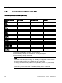
Table 3- 3
X204-2
X204-2TS
XF204-2
X206-1
XF206-1
P5, P6
X212-2
P1, P2
X204-2LD
P13,
P14
X206-1LD
X212-2LD
P13, P14
Overview of the connection options for IRT devices
Fast Ethernet
Device type SCALANCE
10/100 Mbps
X202-2IRT
X204IRT
XF204IRT
X204IRT
PRO
X2022P
IRT
PRO
X2013P IRT
PRO
X2022P IRT
X201-3P
IRT
X200-4P IRT
TP (RJ-45)
2
4
4
-
-
-
2
1
-
IE RJ-45 Plug PRO
-
-
-
4
2
1
-
-
-
IE SC RJ Plug PRO
-
-
-
-
2
3
-
-
-
Fiber multimode
(BFOC)
2
-
-
-
-
-
-
-
-
Fiber single mode
(BFOC)
-
-
-
-
-
-
-
-
-
Fiber POF / PCF
(SC-RJ)
-
-
-
-
2
3
2
3
4
P3, P4
P1, P2
P1, P2
P1, P2
P3,
P4
P3, P4
P3, P4
P3, P4
P3, P4
The following ports
are set as ring ports
when supplied
SCALANCE X-200
32
Operating Instructions, 12/2011, A5E00349864-19
Product properties
3.2 Components of the product
3.2
Components of the product
The following components ship with the device (except X204 IRT PRO, X202-2P IRT PRO,
X201-3P IRT PRO):
● Device
● 2-pin plug-in terminal block
● 4-pin plug-in terminal block
● Operating Instructions (compact)
● CD (operating instructions, PST Tool, GSD file, SNMP OPC profile)
The following components ship with an X204 IRT PRO, X202-2P IRT PRO,
X201-3P IRT PRO:
● Device
● 4 data connector protective covers
● 2 protective caps for power supply connectors
● 1 protective cap for the M12 signaling contact
● Operating Instructions (compact)
● CD (operating instructions, PST Tool, GSD file, SNMP OPC profile)
SCALANCE X-200
Operating Instructions, 12/2011, A5E00349864-19
33
Product properties
3.3 Unpacking and checking
3.3
Unpacking and checking
Unpacking, checking
1. Make sure that the package is complete.
2. Check all the parts for transport damage.
WARNING
Do not use any parts that show evidence of damage!
SCALANCE X-200
34
Operating Instructions, 12/2011, A5E00349864-19
Product properties
3.4 SCALANCE XF204
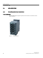
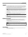
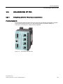
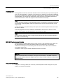
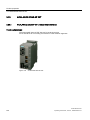
3.4
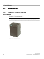
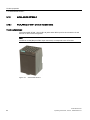
SCALANCE XF204
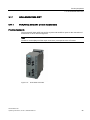
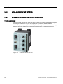
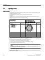
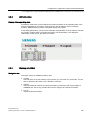
3.4.1
SCALANCE XF204 product characteristics
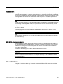
Possible attachments
The SCALANCE XF204 has four RJ-45 jacks for connecting end devices or other network
segments.
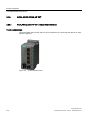
Figure 3-1
SCALANCE XF204
SCALANCE X-200
Operating Instructions, 12/2011, A5E00349864-19
35
Product properties
3.4 SCALANCE XF204
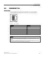
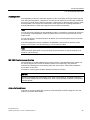
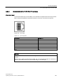
3.4.2
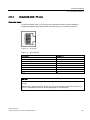
SCALANCE XF204 TP ports
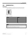
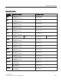
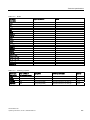
Connector pinout
On the SCALANCE XF204, the TP ports are implemented as RJ-45 jacks with the MDI-X
assignment (Medium Dependent Interface Autocrossover) of a network component.
Figure 3-2
RJ-45 jack
Table 3- 4
Pin assignment
Pin number
Assignment
Pin 8
n. c.
Pin 7
n. c.
Pin 6
TD-
Pin 5
n. c.
Pin 4
n. c.
Pin 3
TD+
Pin 2
RD-
Pin 1
RD+
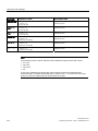
NOTICE
TP cords or TP-XP cords with a maximum length of 10 m can be connected to the RJ-45
TP port.
With the IE FC cables and IE FC RJ-45 plug 180, an overall cable length of up to 100 m is
permitted between two devices depending on the cable type.
SCALANCE X-200
36
Operating Instructions, 12/2011, A5E00349864-19
Product properties
3.4 SCALANCE XF204
Autonegotiation
Autonegotiation means the automatic detection of the functionality of the port at the opposite
end. Using autonegotiation, repeaters or end devices can detect the functionality available at
the port of a partner device allowing automatic configuration of different types of device. With
autonegotiation, two components connected to a link segment can exchange parameters
and set themselves to match the supported communication functionality.
NOTICE
If an IE switch port operating in autonegotiation mode is connected to a partner device that
is not operating in autonegotiation mode, the partner device must be set permanently to
half duplex mode.
If an IE switch port is set permanently to full duplex, the connected partner device must also
be set to full duplex.
If the autonegotiation function is disabled, the MDI/MDI-X autocrossover function is also
inactive. This means it may be necessary to use a crossover cable.
Note
The SCALANCE XF204 is a plug-and-play device that does not require settings to be made
for commissioning.
MDI / MDIX autocrossover function
The advantage of the MDI / MDIX autocrossover function is that straight-through cables can
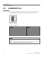
be used throughout and external Ethernet crossover cables are unnecessary. This prevents
malfunctions resulting from mismatching send and receive wires. This makes installation
much easier for the user.
IE Switches XF-200 support the MDI / MDIX autocrossover function.
NOTICE
Please note that the direct connection of two ports on the switch or accidental connection
over several switches causes an illegal loop. Such a loop can lead to network overload and
network failures.
Auto polarity exchange
If the pair of receiving cables are incorrectly connected (RD+ and RD- swapped over), the
polarity is reversed automatically.
SCALANCE X-200
Operating Instructions, 12/2011, A5E00349864-19
37
Product properties
3.5 SCALANCE X208
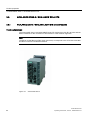
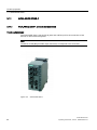
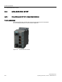
3.5
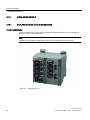
SCALANCE X208
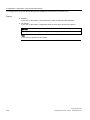
3.5.1
SCALANCE X208 product characteristics
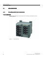
Possible attachments
The SCALANCE X208 has eight RJ-45 jacks for the connection of end devices or other
network segments.
Figure 3-3
SCALANCE X208
SCALANCE X-200
38
Operating Instructions, 12/2011, A5E00349864-19
Product properties
3.5 SCALANCE X208
3.5.2
SCALANCE X208 TP ports
Connector pinout
On the SCALANCE X208, the TP ports are implemented as RJ--45 jacks with MDI-X
assignment (Medium Dependent Interface–Autocrossover) of a network component.
Figure 3-4
RJ-45 jack
Table 3- 5
Pin assignment
Pin number
Assignment
Pin 8
n. c.
Pin 7
n. c.
Pin 6
TD-
Pin 5
n. c.
Pin 4
n. c.
Pin 3
TD+
Pin 2
RD-
Pin 1
RD+
NOTICE
TP cords or TP-XP cords with a maximum length of 10 m can be connected to the RJ-45
TP port.
With the IE FC cables and IE FC RJ-45 plug 180, an overall cable length of up to 100 m is
permitted between two devices depending on the cable type.
SCALANCE X-200
Operating Instructions, 12/2011, A5E00349864-19
39
Product properties
3.5 SCALANCE X208
Autonegotiation
Autonegotiation means the automatic detection of the functionality of the port at the opposite
end. Using autonegotiation, repeaters or end devices can detect the functionality available at
the port of a partner device allowing automatic configuration of different types of device. With
autonegotiation, two components connected to a link segment can exchange parameters
and set themselves to match the supported communication functionality.
Note
If an IE switch port operating in autonegotiation mode is connected to a partner device that is
not operating in autonegotiation mode, the partner device must be set permanently to half
duplex mode.
If an IE switch port is set permanently to full duplex, the connected partner device must also
be set to full duplex.
If the autonegotiation function is disabled, the MDI/MDI-X autocrossover function is also
inactive. This means it may be necessary to use a crossover cable.
Note
The SCALANCE X208 is a plug-and-play device that does not require settings to be made
for commissioning.
MDI /MDIX autocrossover function
The advantage of the MDI /MDIX autocrossover function is that straight-through cables can
be used throughout and crossover Ethernet cables are unnecessary. This prevents
malfunctions resulting from mismatching send and receive wires. This makes installation
much easier for the user.
IE Switches X-200 support the MDI / MDIX autocrossover function.
NOTICE
Please note that the direct connection of two ports on the switch or accidental connection
over several switches causes an illegal loop. Such a loop can lead to network overload and
network failures.
Auto polarity exchange
If the pair of receiving cables are incorrectly connected (RD+ and RD- swapped over), the
polarity is reversed automatically.
SCALANCE X-200
40
Operating Instructions, 12/2011, A5E00349864-19
Product properties
3.6 SCALANCE XF208
3.6
SCALANCE XF208
3.6.1
SCALANCE XF208 product characteristics
Possible attachments
The SCALANCE XF208 has eight RJ-45 jacks for the connection of end devices or other
network segments.
Figure 3-5
SCALANCE XF208
SCALANCE X-200
Operating Instructions, 12/2011, A5E00349864-19
41
Product properties
3.6 SCALANCE XF208
3.6.2
SCALANCE XF208 TP ports
Connector pinout
On the SCALANCE XF208, the TP ports are implemented as RJ-45 jacks with the MDI-X
assignment (Medium Dependent Interface Autocrossover) of a network component.
Figure 3-6
RJ-45 jack
Table 3- 6
Pin assignment
Pin number
Assignment
Pin 8
n. c.
Pin 7
n. c.
Pin 6
TD-
Pin 5
n. c.
Pin 4
n. c.
Pin 3
TD+
Pin 2
RD-
Pin 1
RD+
NOTICE
TP cords or TP-XP cords with a maximum length of 10 m can be connected to the RJ-45
TP port.
With the IE FC cables and IE FC RJ-45 plug 180, an overall cable length of up to 100 m is
permitted between two devices depending on the cable type.
SCALANCE X-200
42
Operating Instructions, 12/2011, A5E00349864-19
Product properties
3.6 SCALANCE XF208
Autonegotiation
Autonegotiation means the automatic detection of the functionality of the port at the opposite
end. Using autonegotiation, repeaters or end devices can detect the functionality available at
the port of a partner device allowing automatic configuration of different types of device. With
autonegotiation, two components connected to a link segment can exchange parameters
and set themselves to match the supported communication functionality.
Note
If an IE switch port operating in autonegotiation mode is connected to a partner device that is
not operating in autonegotiation mode, the partner device must be set permanently to half
duplex mode.
If an IE switch port is set permanently to full duplex, the connected partner device must also
be set to full duplex.
If the autonegotiation function is disabled, the MDI/MDI-X autocrossover function is also
inactive. This means it may be necessary to use a crossover cable.
Note
The SCALANCE XF208 is a plug-and-play device that does not require settings to be made
for commissioning.
MDI / MDIX autocrossover function
The advantage of the MDI / MDIX autocrossover function is that straight-through cables can
be used throughout and external Ethernet crossover cables are unnecessary. This prevents
malfunctions resulting from mismatching send and receive wires. This makes installation
much easier for the user.
IE Switches XF-200 support the MDI / MDIX autocrossover function.
NOTICE
Please note that a direct connection of two ports on the switch or an accidental connection
across several switches causes a forbidden loop. Such a loop can lead to network overload
and network failures.
Auto polarity exchange
If the pair of receiving cables are incorrectly connected (RD+ and RD- swapped over), the
polarity is reversed automatically.
SCALANCE X-200
Operating Instructions, 12/2011, A5E00349864-19
43
Product properties
3.7 SCALANCE X216
3.7
SCALANCE X216
3.7.1
SCALANCE X216 product characteristics
Possible attachments
The SCALANCE X216 has 16 RJ-45 jacks for the connection of end devices or other
network segments.
Figure 3-7
SCALANCE X216
SCALANCE X-200
44
Operating Instructions, 12/2011, A5E00349864-19
Product properties
3.7 SCALANCE X216
3.7.2
SCALANCE X216 TP ports
Connector pinout
On the SCALANCE X216, the TP ports are implemented as RJ-45 jacks with MDI-X
assignment (Medium Dependent Interface–Autocrossover) of a network component.
Figure 3-8
RJ-45 jack
Table 3- 7
Pin assignment
Pin number
Assignment
Pin 8
n. c.
Pin 7
n. c.
Pin 6
TD-
Pin 5
n. c.
Pin 4
n. c.
Pin 3
TD+
Pin 2
RD-
Pin 1
RD+
NOTICE
TP cords or TP-XP cords with a maximum length of 10 m can be connected to the RJ-45
TP port.
With the IE FC cables and IE FC RJ-45 plug 180, an overall cable length of up to 100 m is
permitted between two devices depending on the cable type.
SCALANCE X-200
Operating Instructions, 12/2011, A5E00349864-19
45
Product properties
3.7 SCALANCE X216
Autonegotiation
Autonegotiation means the automatic detection of the functionality of the port at the opposite
end. Using autonegotiation, repeaters or end devices can detect the functionality available at
the port of a partner device allowing automatic configuration of different types of device. With
autonegotiation, two components connected to a link segment can exchange parameters
and set themselves to match the supported communication functionality.
Note
If an IE switch port operating in autonegotiation mode is connected to a partner device that is
not operating in autonegotiation mode, the partner device must be set permanently to half
duplex mode.
If an IE switch port is set permanently to full duplex, the connected partner device must also
be set to full duplex.
If the autonegotiation function is disabled, the MDI/MDI-X autocrossover function is also
inactive. This means it may be necessary to use a crossover cable.
Note
The SCALANCE X216 is a plug-and-play device that does not require settings to be made
for commissioning.
MDI /MDIX autocrossover function
The advantage of the MDI /MDIX autocrossover function is that straight-through cables can
be used throughout and crossover Ethernet cables are unnecessary. This prevents
malfunctions resulting from mismatching send and receive wires. This makes installation
much easier for the user.
IE Switches X-200 support the MDI / MDIX autocrossover function.
NOTICE
Please note that the direct connection of two ports on the switch or accidental connection
over several switches causes an illegal loop. Such a loop can lead to network overload and
network failures.
Auto polarity exchange
If the pair of receiving cables are incorrectly connected (RD+ and RD- swapped over), the
polarity is reversed automatically.
SCALANCE X-200
46
Operating Instructions, 12/2011, A5E00349864-19
Product properties
3.8 SCALANCE X224
3.8
SCALANCE X224
3.8.1
SCALANCE X224 product characteristics
Possible attachments
The SCALANCE X224 has 24 RJ-45 jacks for the connection of end devices or other
network segments.
Figure 3-9
SCALANCE X224
SCALANCE X-200
Operating Instructions, 12/2011, A5E00349864-19
47
Product properties
3.8 SCALANCE X224
3.8.2
SCALANCE X224 TP ports
Connector pinout
On the SCALANCE X224, the TP ports are implemented as RJ-45 jacks with MDI-X
assignment (Medium Dependent Interface–Autocrossover) of a network component.
Figure 3-10
RJ-45 jack
Table 3- 8
Pin assignment
Pin number
Assignment
Pin 8
n. c.
Pin 7
n. c.
Pin 6
TD-
Pin 5
n. c.
Pin 4
n. c.
Pin 3
TD+
Pin 2
RD-
Pin 1
RD+
NOTICE
TP cords or TP-XP cords with a maximum length of 10 m can be connected to the RJ-45
TP port.
With the IE FC cables and IE FC RJ-45 plug 180, an overall cable length of up to 100 m is
permitted between two devices depending on the cable type.
SCALANCE X-200
48
Operating Instructions, 12/2011, A5E00349864-19
Product properties
3.8 SCALANCE X224
Autonegotiation
Autonegotiation means the automatic detection of the functionality of the port at the opposite
end. Using autonegotiation, repeaters or end devices can detect the functionality available at
the port of a partner device allowing automatic configuration of different types of device. With
autonegotiation, two components connected to a link segment can exchange parameters
and set themselves to match the supported communication functionality.
Note
If an IE switch port operating in autonegotiation mode is connected to a partner device that is
not operating in autonegotiation mode, the partner device must be set permanently to half
duplex mode.
If an IE switch port is set permanently to full duplex, the connected partner device must also
be set to full duplex.
If the autonegotiation function is disabled, the MDI/MDI-X autocrossover function is also
inactive. This means it may be necessary to use a crossover cable.
Note
The SCALANCE X224 is a plug-and-play device that does not require settings to be made
for commissioning.
MDI /MDIX autocrossover function
The advantage of the MDI /MDIX autocrossover function is that straight-through cables can
be used throughout and crossover Ethernet cables are unnecessary. This prevents
malfunctions resulting from mismatching send and receive wires. This makes installation
much easier for the user.
IE Switches X-200 support the MDI / MDIX autocrossover function.
NOTICE
Please note that the direct connection of two ports on the switch or accidental connection
over several switches causes an illegal loop. Such a loop can lead to network overload and
network failures.
Auto polarity exchange
If the pair of receiving cables are incorrectly connected (RD+ and RD- swapped over), the
polarity is reversed automatically.
SCALANCE X-200
Operating Instructions, 12/2011, A5E00349864-19
49
Product properties
3.9 SCALANCE X204-2 / SCALANCE X204-2TS
3.9
SCALANCE X204-2 / SCALANCE X204-2TS
3.9.1
SCALANCE X204-2 / SCALANCE X204-2TS product features
Possible attachments
The SCALANCE X204-2 and SCALANCE X204-2TS devices have four RJ-45 jacks and two
BFOC interfaces for the connection of end devices or other network segments.
Note
The BFOC socket (Bayonet Fiber Optic Connector) corresponds to the ST socket. Note that
the BFOC socket is a multimode interface.
Figure 3-11
SCALANCE X204-2
SCALANCE X-200
50
Operating Instructions, 12/2011, A5E00349864-19
Product properties
3.9 SCALANCE X204-2 / SCALANCE X204-2TS
3.9.2
SCALANCE X204-2 / SCALANCE X204-2TS TP interfaces
Connector pinout
On the SCALANCE X204-2 and SCALANCE X204-2TS devices, the TP interfaces take the
form of RJ-45 jacks with the MDI-X assignment (Medium Dependent Interface
Autocrossover) of a network component.
Figure 3-12
RJ-45 jack
Table 3- 9
Pin assignment
Pin number
Assignment
Pin 8
n. c.
Pin 7
n. c.
Pin 6
TD-
Pin 5
n. c.
Pin 4
n. c.
Pin 3
TD+
Pin 2
RD-
Pin 1
RD+
NOTICE
TP cords or TP-XP cords with a maximum length of 10 m can be connected to the RJ-45
TP port.
With the IE FC cables and IE FC RJ-45 plug 180, an overall cable length of a maximum of
100 m is permitted between two devices depending on the cable type.
SCALANCE X-200
Operating Instructions, 12/2011, A5E00349864-19
51
Product properties
3.9 SCALANCE X204-2 / SCALANCE X204-2TS
Autonegotiation
Autonegotiation means the automatic detection of the functionality of the port at the opposite
end. Using autonegotiation, repeaters or end devices can detect the functionality available at
the port of a partner device allowing automatic configuration of different types of device. With
autonegotiation, two components connected to a link segment can exchange parameters
and set themselves to match the supported communication functionality.
Note
If an IE switch port operating in autonegotiation mode is connected to a partner device that is
not operating in autonegotiation mode, the partner device must be set permanently to half
duplex mode.
If an IE switch port is set permanently to full duplex, the connected partner device must also
be set to full duplex.
If the autonegotiation function is disabled, the MDI/MDI-X autocrossover function is also
inactive. This means it may be necessary to use a crossover cable.
Note
The SCALANCE X204-2 and the SCALANCE X204-2TS are plug-and-play devices that
require no settings during commissioning.
MDI / MDIX autocrossover function
The advantage of the MDI / MDIX autocrossover function is that straight-through cables can
be used throughout and external Ethernet crossover cables are unnecessary. This prevents
malfunctions resulting from mismatching send and receive wires. This makes installation
much easier for the user.
IE Switches X-200 support the MDI / MDIX autocrossover function.
NOTICE
Please note that the direct connection of two ports on the switch or accidental connection
over several switches causes an illegal loop. Such a loop can lead to network overload and
network failures.
Auto polarity exchange
If the pair of receiving cables are incorrectly connected (RD+ and RD- swapped over), the
polarity is reversed automatically.
SCALANCE X-200
52
Operating Instructions, 12/2011, A5E00349864-19
Product properties
3.9 SCALANCE X204-2 / SCALANCE X204-2TS
3.9.3
SCALANCE X204-2 / SCALANCE X204-2TS FO interfaces
Transmission speed
The transmission speed of the optical Fast Ethernet ports is 100 Mbps.
Transmission mode
The transmission mode for 100Base-FX is specified in the IEEE 802.3 standard.
Since the full duplex mode and the transmission rate cannot be modified for optical
transmission, autonegotiation cannot be selected.
Transmission medium
Data transmission is over multimode fiber-optic cable (FO cable). The wavelength is 1310
nm.
Multimode fiber-optic cables are used with a core of 50 or 62.5 µm; the light source is an
LED.
The outer diameter of the FO cable is 125 µm.
Transmission range
The maximum transmission range (segment length) is up to 5 km depending on the cable
type.
Connectors
The cables are connected over BFOC sockets.
SCALANCE X-200
Operating Instructions, 12/2011, A5E00349864-19
53
Product properties
3.10 SCALANCE XF204-2
3.10
SCALANCE XF204-2
3.10.1
SCALANCE XF204-2 product characteristics
Possible attachments
The SCALANCE XF204-2 has four RJ-45 jacks and two BFOC ports for the connection of
end devices or other network segments.
Note
The BFOC socket (Bayonet Fiber Optic Connector) corresponds to the ST socket.
Figure 3-13
SCALANCE XF204-2
SCALANCE X-200
54
Operating Instructions, 12/2011, A5E00349864-19
Product properties
3.10 SCALANCE XF204-2
3.10.2
SCALANCE XF204-2 TP ports
Connector pinout
On the SCALANCE XF204-2, the TP ports are implemented as RJ-45 jacks with MDI-X
assignment (Medium Dependent Interface–Autocrossover) of a network component.
Figure 3-14
RJ-45 jack
Table 3- 10
Pin assignment
Pin number
Assignment
Pin 8
n. c.
Pin 7
n. c.
Pin 6
TD-
Pin 5
n. c.
Pin 4
n. c.
Pin 3
TD+
Pin 2
RD-
Pin 1
RD+
NOTICE
TP cords or TP-XP cords with a maximum length of 10 m can be connected to the RJ-45
TP port.
With the IE FC cables and IE FC RJ-45 plug 180, an overall cable length of a maximum of
100 m is permitted between two devices depending on the cable type.
SCALANCE X-200
Operating Instructions, 12/2011, A5E00349864-19
55
Product properties
3.10 SCALANCE XF204-2
Autonegotiation
Autonegotiation means the automatic detection of the functionality of the port at the opposite
end. Using autonegotiation, repeaters or end devices can detect the functionality available at
the port of a partner device allowing automatic configuration of different types of device. With
autonegotiation, two components connected to a link segment can exchange parameters
and set themselves to match the supported communication functionality.
Note
If an IE switch port operating in autonegotiation mode is connected to a partner device that is
not operating in autonegotiation mode, the partner device must be set permanently to half
duplex mode.
If an IE switch port is set permanently to full duplex, the connected partner device must also
be set to full duplex.
If the autonegotiation function is disabled, the MDI/MDI-X autocrossover function is also
inactive. This means it may be necessary to use a crossover cable.
Note
The SCALANCE XF204-2 is a plug-and-play device that does not require settings to be
made for commissioning.
MDI / MDIX autocrossover function
The advantage of the MDI / MDIX autocrossover function is that straight-through cables can
be used throughout and external Ethernet crossover cables are unnecessary. This prevents
malfunctions resulting from mismatching send and receive wires. This makes installation
much easier for the user.
IE Switches X-200 support the MDI / MDIX autocrossover function.
NOTICE
Please note that a direct connection of two ports on the switch or an accidental connection
across several switches causes a forbidden loop. Such a loop can lead to network overload
and network failures.
Auto polarity exchange
If the pair of receiving cables are incorrectly connected (RD+ and RD- swapped over), the
polarity is reversed automatically.
SCALANCE X-200
56
Operating Instructions, 12/2011, A5E00349864-19
Product properties
3.10 SCALANCE XF204-2
3.10.3
SCALANCE XF204-2 FO ports
Transmission speed
The transmission speed of the optical Fast Ethernet ports is 100 Mbps.
Transmission mode
The transmission mode for 100Base-FX is specified in the IEEE 802.3 standard.
Since the full duplex mode and the transmission rate cannot be modified for optical
transmission, autonegotiation cannot be selected.
Transmission medium
Data transmission is over multimode fiber-optic cable (FO cable). The wavelength is 1310
nm.
Multimode fiber-optic cables are used with a core of 50 or 62.5 µm; the light source is an
LED.
The outer diameter of the FO cable is 125 µm.
Transmission range
The maximum transmission range (segment length) is up to 5 km depending on the cable
type.
Connectors
The cables are connected over BFOC sockets.
SCALANCE X-200
Operating Instructions, 12/2011, A5E00349864-19
57
Product properties
3.11 SCALANCE X206-1
3.11
SCALANCE X206-1
3.11.1
SCALANCE X206-1 product characteristics
Possible attachments
The SCALANCE X206-1 has six RJ-45 jacks and a BFOC port for the connection of end
devices or other network segments.
Note
The BFOC socket (Bayonet Fiber Optic Connector) corresponds to the ST socket.
Figure 3-15
SCALANCE X206-1
SCALANCE X-200
58
Operating Instructions, 12/2011, A5E00349864-19
Product properties
3.11 SCALANCE X206-1
3.11.2
SCALANCE X206-1 TP ports
Connector pinout
On the SCALANCE X206-1, the TP ports are implemented as RJ-45 jacks with MDI-X
assignment (Medium Dependent Interface–Autocrossover) of a network component.
Figure 3-16
RJ-45 jack
Table 3- 11
Pin assignment
Pin number
Assignment
Pin 8
n. c.
Pin 7
n. c.
Pin 6
TD-
Pin 5
n. c.
Pin 4
n. c.
Pin 3
TD+
Pin 2
RD-
Pin 1
RD+
NOTICE
TP cords or TP-XP cords with a maximum length of 10 m can be connected to the RJ-45
TP port.
With the IE FC cables and IE FC RJ-45 plug 180, an overall cable length of a maximum of
100 m is permitted between two devices depending on the cable type.
SCALANCE X-200
Operating Instructions, 12/2011, A5E00349864-19
59
Product properties
3.11 SCALANCE X206-1
Autonegotiation
Autonegotiation means the automatic detection of the functionality of the port at the opposite
end. Using autonegotiation, repeaters or end devices can detect the functionality available at
the port of a partner device allowing automatic configuration of different types of device. With
autonegotiation, two components connected to a link segment can exchange parameters
and set themselves to match the supported communication functionality.
Note
If an IE switch port operating in autonegotiation mode is connected to a partner device that is
not operating in autonegotiation mode, the partner device must be set permanently to half
duplex mode.
If an IE switch port is set permanently to full duplex, the connected partner device must also
be set to full duplex.
If the autonegotiation function is disabled, the MDI/MDI-X autocrossover function is also
inactive. This means it may be necessary to use a crossover cable.
Note
The SCALANCE X206-1 is a plug-and-play device that does not require settings to be made
for commissioning.
MDI /MDIX autocrossover function
The advantage of the MDI /MDIX autocrossover function is that straight-through cables can
be used throughout and crossover Ethernet cables are unnecessary. This prevents
malfunctions resulting from mismatching send and receive wires. This makes installation
much easier for the user.
IE Switches X-200 support the MDI / MDIX autocrossover function.
NOTICE
Please note that the direct connection of two ports on the switch or accidental connection
over several switches causes an illegal loop. Such a loop can lead to network overload and
network failures.
Auto polarity exchange
If the pair of receiving cables are incorrectly connected (RD+ and RD- swapped over), the
polarity is reversed automatically.
SCALANCE X-200
60
Operating Instructions, 12/2011, A5E00349864-19
Product properties
3.11 SCALANCE X206-1
3.11.3
SCALANCE X206-1 FO ports
Transmission speed
The transmission speed of the optical Fast Ethernet ports is 100 Mbps.
Transmission mode
The transmission mode for 100Base-FX is specified in the IEEE 802.3 standard.
Since the full duplex mode and the transmission rate cannot be modified for optical
transmission, autonegotiation cannot be selected.
Transmission medium
Data transmission is over multimode fiber-optic cable (FO cable). The wavelength is 1310
nm.
Multimode fiber-optic cables are used with a core of 50 or 62.5 µm; the light source is an
LED.
The outer diameter of the FO cable is 125 µm.
Transmission range
The maximum transmission range (segment length) is up to 5 km depending on the cable
type.
Connectors
The cables are connected over BFOC sockets.
SCALANCE X-200
Operating Instructions, 12/2011, A5E00349864-19
61
Product properties
3.12 SCALANCE XF206-1
3.12
SCALANCE XF206-1
3.12.1
SCALANCE XF206-1 product characteristics
Possible attachments
The SCALANCE XF206-1 has six RJ-45 jacks and a BFOC port for the connection of end
devices or other network segments.
Note
The BFOC socket (Bayonet Fiber Optic Connector) corresponds to the ST socket.
Figure 3-17
SCALANCE XF206-1
SCALANCE X-200
62
Operating Instructions, 12/2011, A5E00349864-19
Product properties
3.12 SCALANCE XF206-1
3.12.2
SCALANCE XF206-1 TP ports
Connector pinout
On the SCALANCE XF206-1, the TP ports are implemented as RJ-45 jacks with MDI-X
assignment (Medium Dependent Interface–Autocrossover) of a network component.
Figure 3-18
RJ-45 jack
Table 3- 12
Pin assignment
Pin number
Assignment
Pin 8
n. c.
Pin 7
n. c.
Pin 6
TD-
Pin 5
n. c.
Pin 4
n. c.
Pin 3
TD+
Pin 2
RD-
Pin 1
RD+
NOTICE
TP cords or TP-XP cords with a maximum length of 10 m can be connected to the RJ-45
TP port.
With the IE FC cables and IE FC RJ-45 plug 180, an overall cable length of a maximum of
100 m is permitted between two devices depending on the cable type.
SCALANCE X-200
Operating Instructions, 12/2011, A5E00349864-19
63
Product properties
3.12 SCALANCE XF206-1
Autonegotiation
Autonegotiation means the automatic detection of the functionality of the port at the opposite
end. Using autonegotiation, repeaters or end devices can detect the functionality available at
the port of a partner device allowing automatic configuration of different types of device. With
autonegotiation, two components connected to a link segment can exchange parameters
and set themselves to match the supported communication functionality.
Note
If an IE switch port operating in autonegotiation mode is connected to a partner device that is
not operating in autonegotiation mode, the partner device must be set permanently to half
duplex mode.
If an IE switch port is set permanently to full duplex, the connected partner device must also
be set to full duplex.
If the autonegotiation function is disabled, the MDI/MDI-X autocrossover function is also
inactive. This means it may be necessary to use a crossover cable.
Note
The SCALANCE XF206-1 is a plug-and-play device that does not require settings to be
made for commissioning.
MDI / MDIX autocrossover function
The advantage of the MDI / MDIX autocrossover function is that straight-through cables can
be used throughout and external Ethernet crossover cables are unnecessary. This prevents
malfunctions resulting from mismatching send and receive wires. This makes installation
much easier for the user.
IE Switches X-200 support the MDI / MDIX autocrossover function.
NOTICE
Please note that a direct connection of two ports on the switch or an accidental connection
across several switches causes a forbidden loop. Such a loop can lead to network overload
and network failures.
Auto polarity exchange
If the pair of receiving cables are incorrectly connected (RD+ and RD- swapped over), the
polarity is reversed automatically.
SCALANCE X-200
64
Operating Instructions, 12/2011, A5E00349864-19
Product properties
3.12 SCALANCE XF206-1
3.12.3
SCALANCE XF206-1 FO ports
Transmission speed
The transmission speed of the optical Fast Ethernet ports is 100 Mbps.
Transmission mode
The transmission mode for 100Base-FX is specified in the IEEE 802.3 standard.
Since the full duplex mode and the transmission rate cannot be modified for optical
transmission, autonegotiation cannot be selected.
Transmission medium
Data transmission is over multimode fiber-optic cable (FO cable). The wavelength is 1310
nm.
Multimode fiber-optic cables are used with a core of 50 or 62.5 µm; the light source is an
LED.
The outer diameter of the FO cable is 125 µm.
Transmission range
The maximum transmission range (segment length) is up to 5 km depending on the cable
type.
Connectors
The cables are connected over BFOC sockets.
SCALANCE X-200
Operating Instructions, 12/2011, A5E00349864-19
65
Product properties
3.13 SCALANCE X212-2
3.13
SCALANCE X212-2
3.13.1
SCALANCE X212-2 product characteristics
Possible attachments
The SCALANCE X212-2 has 12 RJ-45 jacks and two BFOC interfaces for connecting end
devices or other network segments.
Note
The BFOC socket (Bayonet Fiber Optic Connector) corresponds to the ST socket
Figure 3-19
SCALANCE X 212-2
SCALANCE X-200
66
Operating Instructions, 12/2011, A5E00349864-19
Product properties
3.13 SCALANCE X212-2
3.13.2
SCALANCE X212-2 TP ports
Connector pinout
On the SCALANCE X212-2, the TP ports are implemented as RJ-45 jacks with MDI-X
assignment (Medium Dependent Interface–Autocrossover) of a network component.
Figure 3-20
RJ-45 jack
Table 3- 13
Pin assignment
Pin number
Assignment
Pin 8
n. c.
Pin 7
n. c.
Pin 6
TD-
Pin 5
n. c.
Pin 4
n. c.
Pin 3
TD+
Pin 2
RD-
Pin 1
RD+
NOTICE
TP cords or TP-XP cords with a maximum length of 10 m can be connected to the RJ-45
TP port.
With the IE FC cables and IE FC RJ-45 plug 180, an overall cable length of up to 100 m is
permitted between two devices depending on the cable type.
SCALANCE X-200
Operating Instructions, 12/2011, A5E00349864-19
67
Product properties
3.13 SCALANCE X212-2
Autonegotiation
Autonegotiation means the automatic detection of the functionality of the port at the opposite
end. Using autonegotiation, repeaters or end devices can detect the functionality available at
the port of a partner device allowing automatic configuration of different types of device. With
autonegotiation, two components connected to a link segment can exchange parameters
and set themselves to match the supported communication functionality.
Note
If an IE switch port operating in autonegotiation mode is connected to a partner device that is
not operating in autonegotiation mode, the partner device must be set permanently to half
duplex mode.
If an IE switch port is set permanently to full duplex, the connected partner device must also
be set to full duplex.
If the autonegotiation function is disabled, the MDI/MDI-X autocrossover function is also
inactive. This means it may be necessary to use a crossover cable.
Note
The SCALANCE X212-2 is a plug-and-play device that does not require settings to be made
for commissioning.
MDI /MDIX autocrossover function
The advantage of the MDI /MDIX autocrossover function is that straight-through cables can
be used throughout and crossover Ethernet cables are unnecessary. This prevents
malfunctions resulting from mismatching send and receive wires. This makes installation
much easier for the user.
IE Switches X-200 support the MDI / MDIX autocrossover function.
NOTICE
Please note that the direct connection of two ports on the switch or accidental connection
over several switches causes an illegal loop. Such a loop can lead to network overload and
network failures.
Auto polarity exchange
If the pair of receiving cables are incorrectly connected (RD+ and RD- swapped over), the
polarity is reversed automatically.
SCALANCE X-200
68
Operating Instructions, 12/2011, A5E00349864-19
Product properties
3.13 SCALANCE X212-2
3.13.3
SCALANCE X212-2 FO ports
Transmission speed
The transmission speed of the optical Fast Ethernet ports is 100 Mbps.
Transmission mode
The transmission mode for 100Base-FX is specified in the IEEE 802.3 standard.
Since the full duplex mode and the transmission rate cannot be modified for optical
transmission, autonegotiation cannot be selected.
Transmission medium
Data transmission is over multimode fiber-optic cable (FO cable). The wavelength is 1310
nm.
Multimode fiber-optic cables are used with a core of 50 or 62.5 µm; the light source is an
LED.
The outer diameter of the FO cable is 125 µm.
Transmission range
The maximum transmission range (segment length) is up to 5 km depending on the cable
type.
Connectors
The cables are connected over BFOC sockets.
SCALANCE X-200
Operating Instructions, 12/2011, A5E00349864-19
69
Product properties
3.14 SCALANCE X204-2LD
3.14
SCALANCE X204-2LD
3.14.1
SCALANCE X204-2LD product characteristics
Possible attachments
The SCALANCE X204-2LD has four RJ-45 jacks and two BFOC ports for the connection of
end devices or other network segments.
Note
The BFOC socket (Bayonet Fiber Optic Connector) corresponds to the ST socket.
Figure 3-21
SCALANCE X204-2LD
SCALANCE X-200
70
Operating Instructions, 12/2011, A5E00349864-19
Product properties
3.14 SCALANCE X204-2LD
3.14.2
SCALANCE X204-2LD TP ports
Connector pinout
On the SCALANCE X204-2LD, the TP ports are implemented as RJ-45 jacks with MDI-X
assignment (Medium Dependent Interface–Autocrossover) of a network component.
Figure 3-22
RJ-45 jack
Table 3- 14
Pin assignment
Pin number
Assignment
Pin 8
n. c.
Pin 7
n. c.
Pin 6
TD-
Pin 5
n. c.
Pin 4
n. c.
Pin 3
TD+
Pin 2
RD-
Pin 1
RD+
NOTICE
TP cords or TP-XP cords with a maximum length of 10 m can be connected to the RJ-45
TP port.
With the IE FC cables and IE FC RJ-45 plug 180, an overall cable length of a maximum of
100 m is permitted between two devices depending on the cable type.
SCALANCE X-200
Operating Instructions, 12/2011, A5E00349864-19
71
Product properties
3.14 SCALANCE X204-2LD
Autonegotiation
Autonegotiation means the automatic detection of the functionality of the port at the opposite
end. Using autonegotiation, repeaters or end devices can detect the functionality available at
the port of a partner device allowing automatic configuration of different types of device. With
autonegotiation, two components connected to a link segment can exchange parameters
and set themselves to match the supported communication functionality.
Note
If an IE switch port operating in autonegotiation mode is connected to a partner device that is
not operating in autonegotiation mode, the partner device must be set permanently to half
duplex mode.
If an IE switch port is set permanently to full duplex, the connected partner device must also
be set to full duplex.
If the autonegotiation function is disabled, the MDI/MDI-X autocrossover function is also
inactive. This means it may be necessary to use a crossover cable.
Note
The SCALANCE X204-2LD is a plug-and-play device that does not require settings to be
made for commissioning.
MDI /MDIX autocrossover function
The advantage of the MDI /MDIX autocrossover function is that straight-through cables can
be used throughout and crossover Ethernet cables are unnecessary. This prevents
malfunctions resulting from mismatching send and receive wires. This makes installation
much easier for the user.
IE Switches X-200 support the MDI / MDIX autocrossover function.
NOTICE
Please note that the direct connection of two ports on the switch or accidental connection
over several switches causes an illegal loop. Such a loop can lead to network overload and
network failures.
Auto polarity exchange
If the pair of receiving cables are incorrectly connected (RD+ and RD- swapped over), the
polarity is reversed automatically.
SCALANCE X-200
72
Operating Instructions, 12/2011, A5E00349864-19
Product properties
3.14 SCALANCE X204-2LD
3.14.3
SCALANCE X204-2LD TP ports
Transmission rate
The transmission speed of the optical Fast Ethernet ports is 100 Mbps.
Transmission mode
The transmission mode for 100Base-FX is specified in the IEEE 802.3 standard.
Since the full duplex mode and the transmission rate cannot be modified for optical
transmission, autonegotiation cannot be selected.
Transmission medium
Data transmission is over single mode fiber-optic cable (FOC). The wavelength is 1310 nm.
Single mode fiber-optic cables are used with a core of 9 µm; the light source is an LED.
The outer diameter of the FOC is 125 µm.
Transmission range
The maximum transmission range (segment length) is 26 km.
SCALANCE X-200
Operating Instructions, 12/2011, A5E00349864-19
73
Product properties
3.14 SCALANCE X204-2LD
Connectors
The cables are connected over BFOC sockets.
Note
The SCALANCE X204-2LD may only be coupled over its optical ports with
SCALANCE X204-2LD
SCALANCE X206-1LD
SCALANCE X212-2LD
SCALANCE X-400 with module type MM491-2LD
SCALANCE X101-LD
OMC TP11-LD
OSM ITP62-LD
Coupling optical ports with
SCALANCE X106-1
SCALANCE X104-2
SCALANCE X206-1
SCALANCE XF206-1
SCALANCE X204-2
SCALANCE XF204-2
SCALANCE X202-2IRT
SCALANCE X212-2
SCALANCE X-400 with module type MM491-2
OMC TP11
OSM ITP62
OSM ITP53
OSM TP62
is not permitted.
SCALANCE X-200
74
Operating Instructions, 12/2011, A5E00349864-19
Product properties
3.15 SCALANCE X206-1LD
3.15
SCALANCE X206-1LD
3.15.1
SCALANCE X206-1LD product characteristics
Possible attachments
The SCALANCE X206-1LD has six RJ-45 jacks and a BFOC port for the connection of end
devices or other network segments.
Note
The BFOC socket (Bayonet Fiber Optic Connector) corresponds to the ST socket.
Figure 3-23
SCALANCE X206-1LD
SCALANCE X-200
Operating Instructions, 12/2011, A5E00349864-19
75
Product properties
3.15 SCALANCE X206-1LD
3.15.2
SCALANCE X206-1LD TP ports
Connector pinout
On the SCALANCE X206-1LD, the TP ports are implemented as RJ-45 jacks with MDI-X
assignment (Medium Dependent Interface–Autocrossover) of a network component.
Figure 3-24
RJ-45 jack
Table 3- 15
Pin assignment
Pin number
Assignment
Pin 8
n. c.
Pin 7
n. c.
Pin 6
TD-
Pin 5
n. c.
Pin 4
n. c.
Pin 3
TD+
Pin 2
RD-
Pin 1
RD+
NOTICE
TP cords or TP-XP cords with a maximum length of 10 m can be connected to the RJ-45
TP port.
With the IE FC cables and IE FC RJ-45 plug 180, an overall cable length of a maximum of
100 m is permitted between two devices depending on the cable type.
SCALANCE X-200
76
Operating Instructions, 12/2011, A5E00349864-19
Product properties
3.15 SCALANCE X206-1LD
Autonegotiation
Autonegotiation means the automatic detection of the functionality of the port at the opposite
end. Using autonegotiation, repeaters or end devices can detect the functionality available at
the port of a partner device allowing automatic configuration of different types of device. With
autonegotiation, two components connected to a link segment can exchange parameters
and set themselves to match the supported communication functionality.
Note
If an IE switch port operating in autonegotiation mode is connected to a partner device that is
not operating in autonegotiation mode, the partner device must be set permanently to half
duplex mode.
If an IE switch port is set permanently to full duplex, the connected partner device must also
be set to full duplex.
If the autonegotiation function is disabled, the MDI/MDI-X autocrossover function is also
inactive. This means it may be necessary to use a crossover cable.
Note
The SCALANCE X206-1LD is a plug-and-play device that does not require settings to be
made for commissioning.
MDI /MDIX autocrossover function
The advantage of the MDI /MDIX autocrossover function is that straight-through cables can
be used throughout and crossover Ethernet cables are unnecessary. This prevents
malfunctions resulting from mismatching send and receive wires. This makes installation
much easier for the user.
IE Switches X-200 support the MDI / MDIX autocrossover function.
NOTICE
Please note that the direct connection of two ports on the switch or accidental connection
over several switches causes an illegal loop. Such a loop can lead to network overload and
network failures.
Auto polarity exchange
If the pair of receiving cables are incorrectly connected (RD+ and RD- swapped over), the
polarity is reversed automatically.
SCALANCE X-200
Operating Instructions, 12/2011, A5E00349864-19
77
Product properties
3.15 SCALANCE X206-1LD
3.15.3
SCALANCE X206-1LD FO ports
Transmission rate
The transmission speed of the optical Fast Ethernet ports is 100 Mbps.
Transmission mode
The transmission mode for 100Base-FX is specified in the IEEE 802.3 standard.
Since the full duplex mode and the transmission rate cannot be modified for optical
transmission, autonegotiation cannot be selected.
Transmission medium
Data transmission is over single mode fiber-optic cable (FOC). The wavelength is 1310 nm.
Single mode fiber-optic cables are used with a core of 9 µm; the light source is an LED.
The outer diameter of the FOC is 125 µm.
Transmission range
The maximum transmission range (segment length) is 26 km.
SCALANCE X-200
78
Operating Instructions, 12/2011, A5E00349864-19
Product properties
3.15 SCALANCE X206-1LD
Connectors
The cables are connected over BFOC sockets.
Note
The SCALANCE X206-1LD may only be coupled over its optical ports with
SCALANCE X212-2LD
SCALANCE X204-2LD
SCALANCE X206-1LD
SCALANCE X-400 with module type MM491-2LD
SCALANCE X101-LD
OMC TP11-LD
OSM ITP62-LD
Coupling optical ports with
SCALANCE X106-1
SCALANCE X104-2
SCALANCE X206-1
SCALANCE XF206-1
SCALANCE X204-2
SCALANCE XF204-2
SCALANCE X202-2IRT
SCALANCE X212-2
SCALANCE X-400 with module type MM491-2
OMC TP11
OSM ITP62
OSM ITP53
OSM TP62
is not permitted.
SCALANCE X-200
Operating Instructions, 12/2011, A5E00349864-19
79
Product properties
3.16 SCALANCE X212-2LD
3.16
SCALANCE X212-2LD
3.16.1
SCALANCE X212-2LD product characteristics
Possible attachments
The SCALANCE X212-2LD has twelve RJ-45 jacks and two BFOC ports for the connection
of end devices or other network segments.
Note
The BFOC socket (Bayonet Fiber Optic Connector) corresponds to the ST socket.
Figure 3-25
SCALANCE X 212-2LD
SCALANCE X-200
80
Operating Instructions, 12/2011, A5E00349864-19
Product properties
3.16 SCALANCE X212-2LD
3.16.2
SCALANCE X212-2LD TP ports
Connector pinout
On the SCALANCE X212-2LD, the TP ports are implemented as RJ-45 jacks with MDI-X
assignment (Medium Dependent Interface–Autocrossover) of a network component.
Figure 3-26
RJ-45 jack
Table 3- 16
Pin assignment
Pin number
Assignment
Pin 8
n. c.
Pin 7
n. c.
Pin 6
TD-
Pin 5
n. c.
Pin 4
n. c.
Pin 3
TD+
Pin 2
RD-
Pin 1
RD+
NOTICE
TP cords or TP-XP cords with a maximum length of 10 m can be connected to the RJ-45
TP port.
With the IE FC cables and IE FC RJ-45 plug 180, an overall cable length of up to 100 m is
permitted between two devices depending on the cable type.
SCALANCE X-200
Operating Instructions, 12/2011, A5E00349864-19
81
Product properties
3.16 SCALANCE X212-2LD
Autonegotiation
Autonegotiation means the automatic detection of the functionality of the port at the opposite
end. Using autonegotiation, repeaters or end devices can detect the functionality available at
the port of a partner device allowing automatic configuration of different types of device. With
autonegotiation, two components connected to a link segment can exchange parameters
and set themselves to match the supported communication functionality.
Note
If an IE switch port operating in autonegotiation mode is connected to a partner device that is
not operating in autonegotiation mode, the partner device must be set permanently to half
duplex mode.
If an IE switch port is set permanently to full duplex, the connected partner device must also
be set to full duplex.
If the autonegotiation function is disabled, the MDI/MDI-X autocrossover function is also
inactive. This means it may be necessary to use a crossover cable.
Note
The SCALANCE X212-2LD is a plug-and-play device that does not require settings to be
made for commissioning.
MDI /MDIX autocrossover function
The advantage of the MDI /MDIX autocrossover function is that straight-through cables can
be used throughout and crossover Ethernet cables are unnecessary. This prevents
malfunctions resulting from mismatching send and receive wires. This makes installation
much easier for the user.
IE Switches X-200 support the MDI / MDIX autocrossover function.
NOTICE
Please note that the direct connection of two ports on the switch or accidental connection
over several switches causes an illegal loop. Such a loop can lead to network overload and
network failures.
Auto polarity exchange
If the pair of receiving cables are incorrectly connected (RD+ and RD- swapped over), the
polarity is reversed automatically.
SCALANCE X-200
82
Operating Instructions, 12/2011, A5E00349864-19
Product properties
3.16 SCALANCE X212-2LD
3.16.3
SCALANCE X212-2LD FO ports
Transmission rate
The transmission speed of the optical Fast Ethernet ports is 100 Mbps.
Transmission mode
The transmission mode for 100Base-FX is specified in the IEEE 802.3 standard.
Since the full duplex mode and the transmission rate cannot be modified for optical
transmission, autonegotiation cannot be selected.
Transmission medium
Data transmission is over single mode fiber-optic cable (FOC). The wavelength is 1310 nm.
Single mode fiber-optic cables are used with a core of 9 µm; the light source is an LED.
The outer diameter of the FOC is 125 µm.
Transmission range
The maximum transmission range (segment length) is 26 km.
SCALANCE X-200
Operating Instructions, 12/2011, A5E00349864-19
83
Product properties
3.16 SCALANCE X212-2LD
Connectors
The cables are connected over BFOC sockets.
Note
The SCALANCE X212-2LD may only be coupled over its optical ports with
SCALANCE X212-2LD
SCALANCE X204-2LD
SCALANCE X206-1LD
SCALANCE X-400 with module type MM491-2LD
SCALANCE X101-LD
OMC TP11-LD
OSM ITP62-LD
Coupling optical ports with
SCALANCE X106-1
SCALANCE X104-2
SCALANCE X206-1
SCALANCE XF206-1
SCALANCE X204-2
SCALANCE XF204-2
SCALANCE X202-2IRT
SCALANCE X212-2
SCALANCE X-400 with module type MM491-2
OMC TP11
OSM ITP62
OSM ITP53
OSM TP62
is not permitted.
SCALANCE X-200
84
Operating Instructions, 12/2011, A5E00349864-19
Product properties
3.17 SCALANCE X202-2IRT
3.17
SCALANCE X202-2IRT
3.17.1
SCALANCE X202-2IRT product characteristics
Possible attachments
The SCALANCE X202-2IRT has two RJ-45 jacks and two BFOC ports for the connection of
end devices or other network segments.
Note
The BFOC socket (Bayonet Fiber Optic Connector) corresponds to the ST socket.
Figure 3-27
SCALANCE X202-2IRT
SCALANCE X-200
Operating Instructions, 12/2011, A5E00349864-19
85
Product properties
3.17 SCALANCE X202-2IRT
3.17.2
SCALANCE X202-2IRT TP ports
Connector pinout
On the SCALANCE X202-2IRT, the TP ports are implemented as RJ-45 jacks with MDI-X
assignment (Medium Dependent Interface–Autocrossover) of a network component.
Figure 3-28
RJ-45 jack
Table 3- 17
Pin assignment
Pin number
Assignment
Pin 8
n. c.
Pin 7
n. c.
Pin 6
TD-
Pin 5
n. c.
Pin 4
n. c.
Pin 3
TD+
Pin 2
RD-
Pin 1
RD+
NOTICE
TP cords or TP-XP cords with a maximum length of 10 m can be connected to the RJ-45
TP port.
With the IE FC cables and IE FC RJ-45 plug 180, an overall cable length of a maximum of
100 m is permitted between two devices depending on the cable type.
SCALANCE X-200
86
Operating Instructions, 12/2011, A5E00349864-19
Product properties
3.17 SCALANCE X202-2IRT
Autonegotiation
Autonegotiation means the automatic detection of the functionality of the port at the opposite
end. Using autonegotiation, repeaters or end devices can detect the functionality available at
the port of a partner device allowing automatic configuration of different types of device. With
autonegotiation, two components connected to a link segment can exchange parameters
and set themselves to match the supported communication functionality.
Note
If an IE switch port operating in autonegotiation mode is connected to a partner device that is
not operating in autonegotiation mode, the partner device must be set permanently to half
duplex mode.
If an IE switch port is set permanently to full duplex, the connected partner device must also
be set to full duplex.
If the autonegotiation function is disabled, the MDI/MDI-X autocrossover function is also
inactive. This means it may be necessary to use a crossover cable.
Note
The SCALANCE X202-2IRT is a plug-and-play device that does not require settings to be
made for commissioning.
MDI /MDIX autocrossover function
The advantage of the MDI /MDIX autocrossover function is that straight-through cables can
be used throughout and crossover Ethernet cables are unnecessary. This prevents
malfunctions resulting from mismatching send and receive wires. This makes installation
much easier for the user.
IE Switches X-200 support the MDI / MDIX autocrossover function.
NOTICE
Please note that the direct connection of two ports on the switch or accidental connection
over several switches causes an illegal loop. Such a loop can lead to network overload and
network failures.
Auto polarity exchange
If the pair of receiving cables are incorrectly connected (RD+ and RD- swapped over), the
polarity is reversed automatically.
SCALANCE X-200
Operating Instructions, 12/2011, A5E00349864-19
87
Product properties
3.17 SCALANCE X202-2IRT
3.17.3
SCALANCE X202-2IRT FO ports
Transmission speed
The transmission speed of the optical Fast Ethernet ports is 100 Mbps.
Transmission mode
The transmission mode for 100Base-FX is specified in the IEEE 802.3 standard.
Since the full duplex mode and the transmission rate cannot be modified for optical
transmission, autonegotiation cannot be selected.
Transmission medium
Data transmission is over multimode fiber-optic cable (FO cable). The wavelength is 1310
nm.
Multimode fiber-optic cables are used with a core of 50 or 62.5 µm; the light source is an
LED.
The outer diameter of the FO cable is 125 µm.
Transmission range
The maximum transmission range (segment length) is up to 5 km depending on the cable
type.
Connectors
The cables are connected over BFOC sockets.
SCALANCE X-200
88
Operating Instructions, 12/2011, A5E00349864-19
Product properties
3.18 SCALANCE X204IRT
3.18
SCALANCE X204IRT
3.18.1
SCALANCE X204IRT product characteristics
Possible attachments
The SCALANCE X204IRT has four RJ-45 jacks for connecting end devices or other network
segments.
Figure 3-29
SCALANCE X204IRT
SCALANCE X-200
Operating Instructions, 12/2011, A5E00349864-19
89
Product properties
3.18 SCALANCE X204IRT
3.18.2
SCALANCE X204IRT TP ports
Connector pinout
On the SCALANCE X204IRT, the TP ports are implemented as RJ-45 jacks with MDI-X
assignment (Medium Dependent Interface–Autocrossover) of a network component.
Figure 3-30
RJ-45 jack
Table 3- 18
Pin assignment
Pin number
Assignment
Pin 8
n. c.
Pin 7
n. c.
Pin 6
TD-
Pin 5
n. c.
Pin 4
n. c.
Pin 3
TD+
Pin 2
RD-
Pin 1
RD+
NOTICE
TP cords or TP-XP cords with a maximum length of 10 m can be connected to the RJ-45
TP port.
With the IE FC cables and IE FC RJ-45 plug 180, an overall cable length of up to 100 m is
permitted between two devices depending on the cable type.
SCALANCE X-200
90
Operating Instructions, 12/2011, A5E00349864-19
Product properties
3.18 SCALANCE X204IRT
Autonegotiation
Autonegotiation means the automatic detection of the functionality of the port at the opposite
end. Using autonegotiation, repeaters or end devices can detect the functionality available at
the port of a partner device allowing automatic configuration of different types of device. With
autonegotiation, two components connected to a link segment can exchange parameters
and set themselves to match the supported communication functionality.
Note
If an IE switch port operating in autonegotiation mode is connected to a partner device that is
not operating in autonegotiation mode, the partner device must be set permanently to half
duplex mode.
If an IE switch port is set permanently to full duplex, the connected partner device must also
be set to full duplex.
If the autonegotiation function is disabled, the MDI/MDI-X autocrossover function is also
inactive. This means it may be necessary to use a crossover cable.
Note
The SCALANCE X204IRT is a plug-and-play device that does not require settings to be
made for commissioning.
MDI /MDIX autocrossover function
The advantage of the MDI /MDIX autocrossover function is that straight-through cables can
be used throughout and crossover Ethernet cables are unnecessary. This prevents
malfunctions resulting from mismatching send and receive wires. This makes installation
much easier for the user.
IE Switches X-200 support the MDI / MDIX autocrossover function.
NOTICE
Please note that the direct connection of two ports on the switch or accidental connection
over several switches causes an illegal loop. Such a loop can lead to network overload and
network failures.
Auto polarity exchange
If the pair of receiving cables are incorrectly connected (RD+ and RD- swapped over), the
polarity is reversed automatically.
SCALANCE X-200
Operating Instructions, 12/2011, A5E00349864-19
91
Product properties
3.19 SCALANCE XF204IRT
3.19
SCALANCE XF204IRT
3.19.1
SCALANCE XF204IRT product characteristics
Possible attachments
The SCALANCE XF204IRT has four RJ-45 jacks for connecting end devices or other
network segments.
Figure 3-31
SCALANCE XF204IRT
SCALANCE X-200
92
Operating Instructions, 12/2011, A5E00349864-19
Product properties
3.19 SCALANCE XF204IRT
3.19.2
SCALANCE XF204IRT TP ports
Connector pinout
On the SCALANCE XF204IRT, the TP ports are implemented as RJ-45 jacks with the MDI-X
assignment (Medium Dependent Interface Autocrossover) of a network component.
Figure 3-32
RJ-45 jack
Table 3- 19
Pin assignment
Pin number
Assignment
Pin 8
n. c.
Pin 7
n. c.
Pin 6
TD-
Pin 5
n. c.
Pin 4
n. c.
Pin 3
TD+
Pin 2
RD-
Pin 1
RD+
NOTICE
TP cords or TP-XP cords with a maximum length of 10 m can be connected to the RJ-45
TP port.
With the IE FC cables and IE FC RJ-45 plug 180, an overall cable length of up to 100 m is
permitted between two devices depending on the cable type.
SCALANCE X-200
Operating Instructions, 12/2011, A5E00349864-19
93
Product properties
3.19 SCALANCE XF204IRT
Autonegotiation
Autonegotiation means the automatic detection of the functionality of the port at the opposite
end. Using autonegotiation, repeaters or end devices can detect the functionality available at
the port of a partner device allowing automatic configuration of different types of device. With
autonegotiation, two components connected to a link segment can exchange parameters
and set themselves to match the supported communication functionality.
Note
If an IE switch port operating in autonegotiation mode is connected to a partner device that is
not operating in autonegotiation mode, the partner device must be set permanently to half
duplex mode.
If an IE switch port is set permanently to full duplex, the connected partner device must also
be set to full duplex.
If the autonegotiation function is disabled, the MDI/MDI-X autocrossover function is also
inactive. This means it may be necessary to use a crossover cable.
Note
The SCALANCE XF204IRT is a plug-and-play device that does not require settings to be
made for commissioning.
MDI /MDIX autocrossover function
The advantage of the MDI /MDIX autocrossover function is that straight-through cables can
be used throughout and crossover Ethernet cables are unnecessary. This prevents
malfunctions resulting from mismatching send and receive wires. This makes installation
much easier for the user.
IE Switches X-200 support the MDI / MDIX autocrossover function.
NOTICE
Please note that the direct connection of two ports on the switch or accidental connection
over several switches causes an illegal loop. Such a loop can lead to network overload and
network failures.
Auto polarity exchange
If the pair of receiving cables are incorrectly connected (RD+ and RD- swapped over), the
polarity is reversed automatically.
SCALANCE X-200
94
Operating Instructions, 12/2011, A5E00349864-19
Product properties
3.20 SCALANCE X204 IRT PRO
3.20
SCALANCE X204 IRT PRO
3.20.1
SCALANCE X204 IRT PRO product characteristics
Possible attachments
The SCALANCE X204 IRT PRO has four RJ-45 push-pull interfaces (PROFINET-compliant
in accordance with IEC 61076-3-117) with the high degree of protection IP65/67 for
connection of end devices or further network segments.
Figure 3-33
SCALANCE X204 IRT PRO
SCALANCE X-200
Operating Instructions, 12/2011, A5E00349864-19
95
Product properties
3.20 SCALANCE X204 IRT PRO
3.20.2
SCALANCE X204 IRT PRO TP ports
Connector pinout
On the SCALANCE X204 IRT PRO, the TP ports are implemented as RJ-45 jacks with MDIX assignment (Medium Dependent Interface–Autocrossover) of a network component.
Figure 3-34
RJ-45 jack
Table 3- 20
Pin assignment
Pin number
Assignment
Pin 8
n. c.
Pin 7
n. c.
Pin 6
TD-
Pin 5
n. c.
Pin 4
n. c.
Pin 3
TD+
Pin 2
RD-
Pin 1
RD+
NOTICE
TP cords or TP-XP cords with a maximum length of 10 m can be connected to the RJ-45
TP port.
With the IE FC cables and IE RJ-45 Plug PRO 180, an overall cable length of up to 100 m
is permitted between two devices depending on the cable type.
SCALANCE X-200
96
Operating Instructions, 12/2011, A5E00349864-19
Product properties
3.20 SCALANCE X204 IRT PRO
Autonegotiation
Autonegotiation means the automatic detection of the functionality of the port at the opposite
end. Using autonegotiation, repeaters or end devices can detect the functionality available at
the port of a partner device allowing automatic configuration of different types of device. With
autonegotiation, two components connected to a link segment can exchange parameters
and set themselves to match the supported communication functionality.
Note
If an IE switch port operating in autonegotiation mode is connected to a partner device that is
not operating in autonegotiation mode, the partner device must be set permanently to half
duplex mode.
If an IE switch port is set permanently to full duplex, the connected partner device must also
be set to full duplex.
If the autonegotiation function is disabled, the MDI/MDI-X autocrossover function is also
inactive. This means it may be necessary to use a crossover cable.
Note
The SCALANCE X204 IRT PRO is a plug-and-play device that does not require settings to
be made for commissioning.
MDI /MDIX autocrossover function
The advantage of the MDI /MDIX autocrossover function is that straight-through cables can
be used throughout and crossover Ethernet cables are unnecessary. This prevents
malfunctions resulting from mismatching send and receive wires. This makes installation
much easier for the user.
IE Switches X-200 support the MDI / MDIX autocrossover function.
NOTICE
Please note that the direct connection of two ports on the switch or accidental connection
over several switches causes an illegal loop. Such a loop can lead to network overload and
network failures.
Auto polarity exchange
If the pair of receiving cables are incorrectly connected (RD+ and RD- swapped over), the
polarity is reversed automatically.
SCALANCE X-200
Operating Instructions, 12/2011, A5E00349864-19
97
Product properties
3.21 SCALANCE X202-2P IRT PRO
3.21
SCALANCE X202-2P IRT PRO
3.21.1
SCALANCE X202-2P IRT PRO product characteristics
Possible attachments
The SCALANCE X202-2P IRT PRO has two RJ-45 push-pull interfaces (PROFINETcompliant in accordance with IEC 61076-3-117) with the high degree of protection IP65/67
and two
SC RJ push-pull interfaces (PROFINET-compliant in accordance with IEC 61754-24-2) with
the high degree of protection IP65/67 for the connection of the end devices or further
network segments.
Figure 3-35
SCALANCE X202-2P IRT PRO
SCALANCE X-200
98
Operating Instructions, 12/2011, A5E00349864-19
Product properties
3.21 SCALANCE X202-2P IRT PRO
3.21.2
SCALANCE X202-2P IRT PRO TP ports
Connector pinout
On the SCALANCE X202-2P IRT PRO, the TP ports are implemented as RJ-45 ports with
MDI-X assignment (Medium Dependent Interface–Autocrossover) of a network component.
Figure 3-36
RJ-45 jack
Table 3- 21
Pin assignment
Pin number
Assignment
Pin 8
n. c.
Pin 7
n. c.
Pin 6
TD-
Pin 5
n. c.
Pin 4
n. c.
Pin 3
TD+
Pin 2
RD-
Pin 1
RD+
NOTICE
TP cords or TP-XP cords with a maximum length of 10 m can be connected to the RJ-45
TP port.
With the IE FC cables and IE RJ-45 Plug PRO 180, an overall cable length of a maximum
of 100 m is permitted between two devices depending on the cable type.
SCALANCE X-200
Operating Instructions, 12/2011, A5E00349864-19
99
Product properties
3.21 SCALANCE X202-2P IRT PRO
Autonegotiation
Autonegotiation means the automatic detection of the functionality of the port at the opposite
end. Using autonegotiation, repeaters or end devices can detect the functionality available at
the port of a partner device allowing automatic configuration of different types of device. With
autonegotiation, two components connected to a link segment can exchange parameters
and set themselves to match the supported communication functionality.
Note
If an IE switch port operating in autonegotiation mode is connected to a partner device that is
not operating in autonegotiation mode, the partner device must be set permanently to half
duplex mode.
If an IE switch port is set permanently to full duplex, the connected partner device must also
be set to full duplex.
If the autonegotiation function is disabled, the MDI/MDI-X autocrossover function is also
inactive. This means it may be necessary to use a crossover cable.
Note
The SCALANCE X202-2P IRT PRO is a plug-and-play device that does not require settings
to be made for commissioning.
MDI /MDIX autocrossover function
The advantage of the MDI /MDIX autocrossover function is that straight-through cables can
be used throughout and crossover Ethernet cables are unnecessary. This prevents
malfunctions resulting from mismatching send and receive wires. This makes installation
much easier for the user.
IE Switches X-200 all support the MDI / MDIX autocrossover function.
NOTICE
Please note that the direct connection of two ports on the switch or accidental connection
over several switches causes an illegal loop. Such a loop can lead to network overload and
network failures.
Auto polarity exchange
If the pair of receiving cables are incorrectly connected (RD+ and RD- swapped over), the
polarity is reversed automatically.
SCALANCE X-200
100
Operating Instructions, 12/2011, A5E00349864-19
Product properties
3.21 SCALANCE X202-2P IRT PRO
3.21.3
SCALANCE X202-2P IRT PRO FO ports
Transmission rate
The transmission rate of the optical Fast Ethernet ports is 100 Mbps.
Transmission mode
Since the full duplex mode and the transmission rate cannot be modified for optical
transmission, autonegotiation cannot be selected.
Transmission medium
Data is transferred using plastic optical fiber (POF) or polymer cladded fiber (PCF). The
wavelength is 650 nm.
POF cables with a core diameter of 980 µm as well as PCF cables with a core diameter of
200 µm are used. The light source is an LED.
Transmission range
The minimum cable length is 1 m. The maximum transmission distance (segment length) is
50 m for POF and 100 m for PCF cables.
Connectors
The cables are connected over SC-RJ sockets.
SCALANCE X-200
Operating Instructions, 12/2011, A5E00349864-19
101
Product properties
3.22 SCALANCE X201-3P IRT PRO
3.22
SCALANCE X201-3P IRT PRO
3.22.1
SCALANCE X201-3P IRT PRO product characteristics
Possible attachments
The SCALANCE X201-3P IRT PRO has an RJ-45 push pull interface (PROFINET-compliant
according to IEC61076-3-117) with the high degree of protection IP65/67, and three
SC RJ push pull interfaces (PROFINET-compliant according to IEC61754-24-2) with the high
degree of protection IP65/67 for connection of end devices or other network segments.
Figure 3-37
SCALANCE X201-3P IRT PRO
SCALANCE X-200
102
Operating Instructions, 12/2011, A5E00349864-19
Product properties
3.22 SCALANCE X201-3P IRT PRO
3.22.2
SCALANCE X201-3P IRT PRO TP interfaces
Connector pinout
On the SCALANCE X201-3P IRT PRO, the TP interface is implemented as RJ-45 ports with
MDI-X assignment (Medium Dependent Interface Crossover) of a network component.
Figure 3-38
RJ-45 jack
Table 3- 22
Pin assignment
Pin number
Assignment
Pin 8
n. c.
Pin 7
n. c.
Pin 6
TD-
Pin 5
n. c.
Pin 4
n. c.
Pin 3
TD+
Pin 2
RD-
Pin 1
RD+
NOTICE
TP cords or TP-XP cords with a maximum length of 10 m can be connected to the RJ-45
TP port.
With the IE FC cables and IE RJ45 Plug PRO 180, an overall cable length of a maximum of
100 m is permitted between two devices depending on the cable type.
SCALANCE X-200
Operating Instructions, 12/2011, A5E00349864-19
103
Product properties
3.22 SCALANCE X201-3P IRT PRO
Autonegotiation
Autonegotiation means the automatic detection of the functionality of the port at the opposite
end. Using autonegotiation, repeaters or end devices can detect the functionality available at
the port of a partner device allowing automatic configuration of different types of device. With
autonegotiation, two components connected to a link segment can exchange parameters
and set themselves to match the supported communication functionality.
Note
If an IE switch port operating in autonegotiation mode is connected to a partner device that is
not operating in autonegotiation mode, the partner device must be set permanently to half
duplex mode.
If an IE switch port is set permanently to full duplex, the connected partner device must also
be set to full duplex.
If the autonegotiation function is disabled, the MDI/MDI-X autocrossover function is also
inactive. This means it may be necessary to use a crossover cable.
Note
The SCALANCE X201-3P IRT PRO is a plug-and-play device that does not require settings
to be made for commissioning.
MDI/MDIX autocrossover function
The advantage of the MDI/MDIX autocrossover function is that straight-through cables can
be used throughout and external Ethernet crossover cables are unnecessary. This prevents
malfunctions resulting from mismatching send and receive wires. This makes installation
much easier for the user.
All IE Switches X-200 support the MDI / MDIX autocrossover function.
NOTICE
Please note that a direct connection of two ports on the switch or an accidental connection
across several switches causes a forbidden loop. Such a loop can lead to network overload
and network failures.
Auto polarity exchange
If the pair of receiving cables are incorrectly connected (RD+ and RD- swapped over), the
polarity is reversed automatically.
SCALANCE X-200
104
Operating Instructions, 12/2011, A5E00349864-19
Product properties
3.22 SCALANCE X201-3P IRT PRO
3.22.3
SCALANCE X201-3P IRT PRO FO interfaces
Transmission rate
The transmission rate of the optical Fast Ethernet ports is 100 Mbps.
Transmission mode
Since the full duplex mode and the transmission rate cannot be modified for optical
transmission, autonegotiation cannot be selected.
Transmission medium
Data is transferred using plastic optical fiber (POF) or polymer cladded fiber (PCF). The
wavelength is 650 nm.
POF cables with a core diameter of 980 µm as well as PCF cables with a core diameter of
200 µm are used. The light source is an LED.
Transmission range
The minimum cable length is 1 m. The maximum transmission distance (segment length) is
50 m for POF and 100 m for PCF cables.
Connectors
The cables are connected over SC-RJ sockets.
SCALANCE X-200
Operating Instructions, 12/2011, A5E00349864-19
105
Product properties
3.23 SCALANCE X202-2P IRT
3.23
SCALANCE X202-2P IRT
3.23.1
SCALANCE X202-2P IRT product characteristics
Possible attachments
The SCALANCE X202-2P IRT has two RJ-45 jacks and two
SC RJ interfaces for connecting end devices or other network segments.
Figure 3-39
SCALANCE X202-2P IRT
SCALANCE X-200
106
Operating Instructions, 12/2011, A5E00349864-19
Product properties
3.23 SCALANCE X202-2P IRT
3.23.2
SCALANCE X202-2P IRT TP ports
Connector pinout
On the SCALANCE X202-2P IRT, the TP ports are implemented as RJ-45 jacks with MDI-X
assignment (Medium Dependent Interface–Autocrossover) of a network component.
Figure 3-40
RJ-45 jack
Table 3- 23
Pin assignment
Pin number
Assignment
Pin 8
n. c.
Pin 7
n. c.
Pin 6
TD-
Pin 5
n. c.
Pin 4
n. c.
Pin 3
TD+
Pin 2
RD-
Pin 1
RD+
NOTICE
TP cords or TP-XP cords with a maximum length of 10 m can be connected to the RJ-45
TP port.
With the IE FC cables and IE FC RJ-45 plug 180, an overall cable length of a maximum of
100 m is permitted between two devices depending on the cable type.
SCALANCE X-200
Operating Instructions, 12/2011, A5E00349864-19
107
Product properties
3.23 SCALANCE X202-2P IRT
Autonegotiation
Autonegotiation means the automatic detection of the functionality of the port at the opposite
end. Using autonegotiation, repeaters or end devices can detect the functionality available at
the port of a partner device allowing automatic configuration of different types of device. With
autonegotiation, two components connected to a link segment can exchange parameters
and set themselves to match the supported communication functionality.
Note
If an IE switch port operating in autonegotiation mode is connected to a partner device that is
not operating in autonegotiation mode, the partner device must be set permanently to half
duplex mode.
If an IE switch port is set permanently to full duplex, the connected partner device must also
be set to full duplex.
If the autonegotiation function is disabled, the MDI/MDI-X autocrossover function is also
inactive. This means it may be necessary to use a crossover cable.
Note
The SCALANCE X202-2P IRT is a plug-and-play device that does not require settings to be
made for commissioning.
MDI /MDIX autocrossover function
The advantage of the MDI /MDIX autocrossover function is that straight-through cables can
be used throughout and crossover Ethernet cables are unnecessary. This prevents
malfunctions resulting from mismatching send and receive wires. This makes installation
much easier for the user.
IE Switches X-200 all support the MDI / MDIX autocrossover function.
NOTICE
Please note that the direct connection of two ports on the switch or accidental connection
over several switches causes an illegal loop. Such a loop can lead to network overload and
network failures.
Auto polarity exchange
If the pair of receiving cables are incorrectly connected (RD+ and RD- swapped over), the
polarity is reversed automatically.
SCALANCE X-200
108
Operating Instructions, 12/2011, A5E00349864-19
Product properties
3.23 SCALANCE X202-2P IRT
3.23.3
SCALANCE X202-2P IRT FO ports
Transmission rate
The transmission rate of the optical Fast Ethernet ports is 100 Mbps.
Transmission mode
Since the full duplex mode and the transmission rate cannot be modified for optical
transmission, autonegotiation cannot be selected.
Transmission medium
Data is transferred using plastic optical fiber (POF) or polymer cladded fiber (PCF). The
wavelength is 650 nm.
POF cables with a core diameter of 980 µm as well as PCF cables with a core diameter of
200 µm are used. The light source is an LED.
Transmission range
The minimum cable length is 1 m. The maximum transmission distance (segment length) is
50 m for POF and 100 m for PCF cables.
Connectors
The cables are connected over SC-RJ sockets.
SCALANCE X-200
Operating Instructions, 12/2011, A5E00349864-19
109
Product properties
3.24 SCALANCE X201-3P IRT
3.24
SCALANCE X201-3P IRT
3.24.1
SCALANCE X201-3P IRT product characteristics
Possible attachments
The SCALANCE X201-3P IRT has an RJ-45 jack and three SC RJ interfaces
for connecting end devices or other network segments.
Figure 3-41
SCALANCE X201-3P IRT
SCALANCE X-200
110
Operating Instructions, 12/2011, A5E00349864-19
Product properties
3.24 SCALANCE X201-3P IRT
3.24.2
SCALANCE X201-3P IRT TP ports
Connector pinout
On the SCALANCE X201-3P IRT, the TP port is implemented as an RJ-45 jack with MDI-X
assignment (Medium Dependent Interface–Autocrossover) of a network component.
Figure 3-42
RJ-45 jack
Table 3- 24
Pin assignment
Pin number
Assignment
Pin 8
n. c.
Pin 7
n. c.
Pin 6
TD-
Pin 5
n. c.
Pin 4
n. c.
Pin 3
TD+
Pin 2
RD-
Pin 1
RD+
NOTICE
TP cords or TP-XP cords with a maximum length of 10 m can be connected to the RJ-45
TP port.
With the IE FC cables and IE FC RJ-45 plug 180, an overall cable length of a maximum of
100 m is permitted between two devices depending on the cable type.
SCALANCE X-200
Operating Instructions, 12/2011, A5E00349864-19
111
Product properties
3.24 SCALANCE X201-3P IRT
Autonegotiation
Autonegotiation means the automatic detection of the functionality of the port at the opposite
end. Using autonegotiation, repeaters or end devices can detect the functionality available at
the port of a partner device allowing automatic configuration of different types of device. With
autonegotiation, two components connected to a link segment can exchange parameters
and set themselves to match the supported communication functionality.
Note
If an IE switch port operating in autonegotiation mode is connected to a partner device that is
not operating in autonegotiation mode, the partner device must be set permanently to half
duplex mode.
If an IE switch port is set permanently to full duplex, the connected partner device must also
be set to full duplex.
If the autonegotiation function is disabled, the MDI/MDI-X autocrossover function is also
inactive. This means it may be necessary to use a crossover cable.
Note
The SCALANCE X201-3P IRT is a plug-and-play device that does not require settings to be
made for commissioning.
MDI /MDIX autocrossover function
The advantage of the MDI /MDIX autocrossover function is that straight-through cables can
be used throughout and crossover Ethernet cables are unnecessary. This prevents
malfunctions resulting from mismatching send and receive wires. This makes installation
much easier for the user.
IE Switches X-200 support the MDI / MDIX autocrossover function.
NOTICE
Please note that the direct connection of two ports on the switch or accidental connection
over several switches causes an illegal loop. Such a loop can lead to network overload and
network failures.
Auto polarity exchange
If the pair of receiving cables are incorrectly connected (RD+ and RD- swapped over), the
polarity is reversed automatically.
SCALANCE X-200
112
Operating Instructions, 12/2011, A5E00349864-19
Product properties
3.24 SCALANCE X201-3P IRT
3.24.3
SCALANCE X201-3P IRT FO ports
Transmission rate
The transmission rate of the optical Fast Ethernet ports is 100 Mbps.
Transmission mode
Since the full duplex mode and the transmission rate cannot be modified for optical
transmission, autonegotiation cannot be selected.
Transmission medium
Data is transferred using plastic optical fiber (POF) or polymer cladded fiber (PCF). The
wavelength is 650 nm.
POF cables with a core diameter of 980 µm as well as PCF cables with a core diameter of
200 µm are used. The light source is an LED.
Transmission range
The minimum cable length is 1 m. The maximum transmission distance (segment length) is
50 m for POF and 100 m for PCF cables.
Connectors
The cables are connected over SC-RJ sockets.
SCALANCE X-200
Operating Instructions, 12/2011, A5E00349864-19
113
Product properties
3.25 SCALANCE X200-4P IRT
3.25
SCALANCE X200-4P IRT
3.25.1
SCALANCE X200-4P IRT product characteristics
Possible attachments
The SCALANCE X200-4P IRT has four SC RJ interfaces for connecting end devices or other
network segments.
Figure 3-43
SCALANCEX200 4PIRT
SCALANCE X-200
114
Operating Instructions, 12/2011, A5E00349864-19
Product properties
3.25 SCALANCE X200-4P IRT
3.25.2
SCALANCE X200-4P IRT FO ports
Transmission rate
The transmission rate of the optical Fast Ethernet ports is 100 Mbps.
Transmission mode
Since the full duplex mode and the transmission rate cannot be modified for optical
transmission, autonegotiation cannot be selected.
Transmission medium
Data is transferred using plastic optical fiber (POF) or polymer cladded fiber (PCF). The
wavelength is 650 nm.
POF cables with a core diameter of 980 µm as well as PCF cables with a core diameter of
200 µm are used. The light source is an LED.
Transmission range
The minimum cable length is 1 m. The maximum transmission distance (segment length) is
50 m for POF and 100 m for PCF cables.
Connectors
The cables are connected over SC-RJ sockets.
SCALANCE X-200
Operating Instructions, 12/2011, A5E00349864-19
115
Product properties
3.26 C-PLUG (configuration plug)
3.26
C-PLUG (configuration plug)
Area of application
The C-PLUG is an exchangeable medium for storage of the configuration and project
engineering data of the basic device. This means that the configuration data remains
available if the basic device is replaced.
How it works
Power is supplied by the basic device. The C-PLUG retains all data permanently when the
power is turned off.
If an empty C-PLUG (factory settings) is inserted, all configuration data of an IE
Switch X-200 is saved to it when the device starts up. Changes to the configuration during
operation are also saved on the C-PLUG without any operator intervention being necessary.
If a C-PLUG is inserted, the configuration stored internally on the basic device is no longer
changed. Al changes made to the configuration during ongoing operation are only stored on
the C-PLUG.
A basic device with an inserted C-PLUG automatically uses the configuration data of the
C-PLUG when it starts up. This is, however, only possible when the data was written by a
compatible device type.
This allows fast and simple replacement of the basic device. If a device is replaced, the CPLUG is taken from the failed component and inserted in the replacement device. The first
time it is started up, the replacement device has the same configuration as the failed device
except for the MAC address set by the vendor.
Compatible devices
As a general rule, the data on the C-PLUG is only compatible with devices having an
identical order number and the same device name.
The device combinations shown in the following table are exceptions. With these devices,
the exchange of the C-PLUG is possible in one direction.
Table 3- 25
Device combinations between which the C-PLUG can be exchanged:
Device type
SCALANCE
C-PLUG created by device with
order number
Compatible with device with
order number
X208
6GK5208-0BA00-2AA3
6GK5208-0BA10-2AA3
X204-2
6GK5204-2BB00-2AA3
6GK5204-2BB10-2AA3
X206-1
6GK5206-1BB00-2AA3
6GK5206-1BB10-2AA3
X204-1LD
6GK5204-2BC00-2AA3
6GK5204-2BC10-2AA3
X206-1LD
6GK5206-1BC00-2AA3
6GK5206-1BC10-2AA3
SCALANCE X-200
116
Operating Instructions, 12/2011, A5E00349864-19
Product properties
3.26 C-PLUG (configuration plug)
Note
Combinations other than those shown in the table are not compatible with each other.
Note
If a C-PLUG is adopted in a compatible device as shown in the table, the system name of
the original device is adopted both in the system name and in the PNIO device name of the
compatible device.
Using a previously written C-PLUG
If you want to insert a C-PLUG that has already been used and has been written to an IE
Switch X-200 with a different configuration, the existing C-PLUG data must first be deleted.
Note
An IE Switch X-200 normally starts up with the configuration of the C-PLUG, assuming this
was written to by a compatible device type. If the C-PLUG was written by an incompatible
device type, the basic device will not start up fully and signals an error. The WBM menu
"System C-PLUG" is displayed automatically. Here, you can use the "Modify C-PLUG"
function to specify whether or not the device operates with a C-PLUG.
If you select operation with a C-PLUG, this can be initialized either with the factory defaults
or with settings from the internal memory of the device.
Diagnostics
Inserting a C-PLUG that does not contain the configuration of a compatible device type,
inadvertently removing the C-PLUG, or general malfunctions of the C-PLUG are indicated by
the diagnostic mechanisms of an IE Switch X-200 (LEDs, PROFINET, SNMP, WBM, etc.).
Inserting in the C-PLUG slot
The C-PLUG is not supplied with the IE Switches X-200. It is available as an optional
accessory.
The slot for the C-PLUG is located as follows:
● On the IE Switch X-200 on the back of the device
● On the IE Switch XF-200 on the left hand side of the device
SCALANCE X-200
Operating Instructions, 12/2011, A5E00349864-19
117
Product properties
3.26 C-PLUG (configuration plug)
To insert the C-PLUG, remove the screw cover. The C-PLUG is inserted in the receptacle.
The screw cover must then be closed correctly.
NOTICE
The C-PLUG may only be inserted or removed when the power is off!
Removing the C-PLUG
It is only necessary to remove the C-PLUG if the IE Switch X-200 develops a fault.
The C-PLUG can be removed from the slot using flat pliers, tweezers, or a small screwdriver.
If a C-PLUG has been taken from a device, when the device is restarted, an error message
is output in Web Based Management and in the Command Line Interface.
In this case, you will need to set the device to operation without C-PLUG. For further
information, refer to the section "System C-PLUG WBM menu".
Figure 3-44
Removing the C-PLUG from the receptacle
SCALANCE X-200
118
Operating Instructions, 12/2011, A5E00349864-19
Product properties
3.27 Button
3.27
Button
Button function
You can change various device settings with the button. Modified settings are retained after
device power off/on.
Different settings are made depending on how long you hold down the button:
3KDVH
V
3KDVH
V
3KDVH
V
3KDVH
V
3KDVH
V
3KDVH
V
7LPHEXWWRQSUHVVHG
LQVHFRQGV
Phase
1
Description
The currently set fault mask is displayed. If no fault mask has been set, all ports flash one after the other.
If you release the button in phase 1, this has no effect.
2
The LEDs of the ports at which there is currently a link flash at 2.5 Hz.
If you release the button in phase 2, this has no effect.
3
The LEDs of the ports at which there is currently a link and the LEDs of the connected power supply are lit
permanently.
If you release the button in phase 3, the fault mask corresponding to the lit LEDs is adopted.
4
The RM LED flashes.
Releasing the button in phase 4 turns off the redundancy manager. The redundancy function remains enabled.
The device changes to "Automatic Redundancy Detect" mode.
5
The RM LED is lit permanently.
If you release the button in phase 5, the redundancy function is enabled and the device is configured as HSR
manager.
6
All LEDs flash.
The device is reset to the factory defaults.
Note
On the SCALANCE X204 IRT PRO, SCALANCE X202-2P IRT PRO and SCALANCE X2013P IRT PRO, the button is beneath the C-PLUG cover on the rear of the device.
On the SCALANCE XF-200, the button is below the front panel.
SCALANCE X-200
Operating Instructions, 12/2011, A5E00349864-19
119
Product properties
3.28 Displays
3.28
Displays
3.28.1
Fault indicator (red LED)
Fault indicator (red LED)
If the red LED is lit, the IE Switch X-200 has detected a problem.
The signaling contact opens at the same time provided that the behavior of the signaling
contact was not configured differently.
The LED signals that the IE Switch X-200 can adopt the following statuses:
Device type SCALANCE
LED lit red
LED flashing red
LED not lit
XF204
1, 2, 3, 4, 5, 6, 10
9
11
X208
1, 2, 3, 4, 5, 6, 10
9
11
XF208
1, 2, 3, 4, 5, 6, 10
9
11
X216
1, 2, 3, 4, 5, 6, 10
9
11
X224
1, 2, 3, 4, 5, 6, 10
9
11
X204-2
1, 2, 3, 4, 5, 6, 10
9
11
X204-2TS
1, 2, 3, 4, 5, 6, 10
9
11
XF204-2
1, 2, 3, 4, 5, 6, 10
9
11
X206-1
1, 2, 3, 4, 5, 6, 10
9
11
XF206-1
1, 2, 3, 4, 5, 6, 10
9
11
X212-2
1, 2, 3, 4, 5, 6, 10
9
11
X204-2LD
1, 2, 3, 4, 5, 6, 10
9
11
X206-1LD
1, 2, 3, 4, 5, 6, 10
9
11
X212-2LD
1, 2, 3, 4, 5, 6, 10
9
11
X202-2IRT
1, 2, 3, 4, 5, 6, 7
9
11
X204IRT
1, 2, 3, 4, 5, 6, 7
9
11
XF204IRT
1, 2, 3, 4, 5, 6, 7
9
11
X204 IRT PRO
1, 3, 4, 5, 6, 7
9
11
X202-2P IRT PRO
1, 3, 4, 5, 6, 7, 8
9
11
X201-3P IRT PRO
1, 3, 4, 5, 6, 7, 8
9
11
X202-2P IRT
1, 2, 3, 4, 5, 6, 7, 8
9
11
X201-3P IRT
1, 2, 3, 4, 5, 6, 7, 8
9
11
X200-4P IRT
1, 2, 3, 4, 5, 6, 7, 8
9
11
SCALANCE X-200
120
Operating Instructions, 12/2011, A5E00349864-19
Product properties
3.28 Displays
1. Link down event on a monitored port.
2. Failure of one of the two redundant power supplies.
Note
The following devices do not have a redundant power supply:
SCALANCE X204 IRT PRO
SCALANCE X202-2P IRT PRO
SCALANCE X201-3P IRT PRO
3. C-PLUG
4. Device startup, the LED is lit for approx. 20 seconds.
5. Device is in PROFINET mode:
– a) There is no connection to the controller
– b) There is a connection to the controller, there is also a configured diagnostic
interrupt, for example power fail interrupt, C-PLUG interrupt etc.
6. Redundancy manager connected through.
7. Switchover of standby connection.
8. Maintenance request or maintenance requirement.
9. An internal fault was detected. Inform the maintenance personnel and, if necessary, send
the device in for repair.
10.A loop was detected by the loop detection.
11.No fault detected by the IE Switch X-200.
3.28.2
Power display
SCALANCE X-200
Operating Instructions, 12/2011, A5E00349864-19
121
Product properties
3.28 Displays
Power display
The LEDs signal that the IE Switch X-200 can adopt the following statuses:
The status of the power supply is indicated by a green/yellow LED:
Device type
Yellow-green LED
SCALANCE
LED lit green
LED not lit
LED lit yellow
XF204
1
2
X208
1
2
3
3
XF208
1
2
3
X216
1
2
3
X224
1
2
3
X204-2
1
2
3
X204-2TS
1
2
4
XF204-2
1
2
3
X206-1
1
2
3
XF206-1
1
2
3
X212-2
1
2
3
X204-2LD
1
2
3
X206-1LD
1
2
3
X212-2LD
1
2
3
X202-2IRT
1
2
3
X204IRT
1
2
3
XF204IRT
1
2
3
X204 IRT PRO
1
2
3
X202-2P IRT PRO
1
2
3
X201-3P IRT PRO
1
2
3
X202-2P IRT
1
2
3
X201-3P IRT
1
2
3
X200-4P IRT
1
2
3
1. Both L power supplies are connected (redundant supply).
2. One L power supply is connected (non-redundant supply).
3. Power supply L1 and L2 not connected or <14 V.
4. Power supplies L1 and L2 are not connected.
Note
SCALANCE X204 IRT PRO and SCALANCE X202-2P IRT PRO have no redundant
power supply.
SCALANCE X-200
122
Operating Instructions, 12/2011, A5E00349864-19
Product properties
3.28 Displays
3.28.3
Port status indicator (green/yellow LEDs)
Port status indicator (green/yellow LEDs)
The LEDs signal that the IE Switch X-200 can adopt the following statuses.
The status of the interfaces is indicated by two-color LEDs:
Device type SCALANCE
LED lit green
LED lit yellow
LED flashes
yellow
LED flashes
green
Number of port
LEDs
XF204
4 port LEDs
1
2, 3
4
5, 6
X208
8 port LEDs
1
2, 3
4
5, 6
XF208
8 port LEDs
1
2, 3
4
5, 6
X204-2
6 port LEDs
1
2, 3
4
5, 6
X204-2TS
6 port LEDs
1
2, 3
4
5, 6
XF204-2
6 port LEDs
1
2, 3
4
5, 6
X206-1
7 port LEDs
1
2, 3
4
5, 6
XF206-1
7 port LEDs
1
2, 3
4
5, 6
X204-2LD
6 port LEDs
1
2, 3
4
5, 6
X206-1LD
7 port LEDs
1
2, 3
4
5, 6
X202-2IRT
4 port LEDs
1
2, 3
4
5, 6
X204IRT
4 port LEDs
1
2, 3
4
5, 6
XF204IRT
4 port LEDs
1
2, 3
4
5, 6
X204 IRT PRO
4 port LEDs
1
2, 3
4
5, 6
X202-2P IRT PRO
4 port LEDs
1
2, 3
4
5, 6
X201-3P IRT PRO
4 port LEDs
1
2, 3
4
5, 6
X202-2P IRT
4 port LEDs
1
2, 3
4
5, 6
X201-3P IRT
4 port LEDs
1
2, 3
4
5, 6
X200-4P IRT
4 port LEDs
1
2, 3
4
5, 6
X216
16 port LEDs
1
2, 3
4
5, 6
X212-2
14 port LEDs
1
2, 3
4
5, 6
X212-2LD
14 port LEDs
1
2, 3
4
5, 6
X224
24 port LEDs
1
2, 3
4
5, 6
1. TP link exists, no data reception.
2. TP link, data received at TP port.
3. Device startup, the LED is lit for approx. 6 seconds.
4. Setting or display of the fault mask.
5. The "Show Location" function was enabled over Ethernet (for example, PST tool).
The button was pressed for longer than 15 seconds to reset the configuration.
6. PROFINET IO operation was started with the PN IO controller, the attempt to change the
fault mask with the button was rejected by all the port LEDs flashing once.
SCALANCE X-200
Operating Instructions, 12/2011, A5E00349864-19
123
Product properties
3.28 Displays
3.28.4
Redundancy manager indicator (green LED)
Redundancy manager indicator (green LED)
The LED signals that the IE Switch X-200 can adopt the following statuses:
Device type SCALANCE
LED lit green
LED flashes green
LED not lit
XF204
1
2
3
X208
1
2
3
XF208
1
2
3
X216
1
2
3
X224
1
2
3
X204-2
1
2
3
X204-2TS
1
2
3
XF204-2
1
2
3
X206-1
1
2
3
XF206-1
1
2
3
X212-2
1
2
3
X204-2LD
1
2
3
X206-1LD
1
2
3
X212-2LD
1
2
3
X202-2IRT
1
2
3
X204IRT
1
2
3
XF204IRT
1
2
3
X204 IRT PRO
1
2
3
X202-2P IRT PRO
1
2
3
X201-3P IRT PRO
1
2
3
X202-2P IRT
1
2
3
X201-3P IRT
1
2
3
X200-4P IRT
1
2
3
1. The device is redundancy manager. The ring is closed.
2. The redundancy manager has switched over. The ring is interrupted.
3. The redundancy manager is disabled.
Note
The status of the redundancy manager and standby are displayed as a double function
by a single multicolor LED. This is identified on the device by RM.
It changes its color depending on the function (redundancy function -> green, standby
function -> yellow).
In Web Based Management, the LED is labeled differently depending on the function
(redundancy function, basic status -> label RM, standby function -> label SB).
SCALANCE X-200
124
Operating Instructions, 12/2011, A5E00349864-19
Product properties
3.28 Displays
3.28.5
Standby functions (yellow LED)
Standby functions (yellow LED)
The LED signals that the IE Switch X-200IRT can adopt the following statuses:
Device type SCALANCE
LED lit yellow
LED flashes yellow
(slowly)
LED flashes yellow
(fast)
LED not lit
XF204
-
-
-
X208
-
-
-
-
XF208
-
-
-
-
X216
-
-
-
-
X224
-
-
-
-
X204-2
-
-
-
-
X204-2TS
-
-
-
-
XF204-2
-
-
-
-
X206-1
-
-
-
-
XF206-1
-
-
-
-
X212-2
-
-
-
-
X204-2LD
-
-
-
-
X206-1LD
-
-
-
-
X212-2LD
-
-
-
-
X202-2IRT
1
2
3
4
X204IRT
1
2
3
4
XF204IRT
1
2
3
4
X204 IRT PRO
1
2
3
4
X202-2P IRT PRO
1
2
3
4
X201-3P IRT PRO
1
2
3
4
X202-2P IRT
1
2
3
4
X201-3P IRT
1
2
3
4
X200-4P IRT
1
2
3
4
1. Standby function is enabled (IE Switch X-200 is in standby active mode).
2. Standby function is enabled (IE Switch X-200 is in standby passive mode).
SCALANCE X-200
Operating Instructions, 12/2011, A5E00349864-19
125
Product properties
3.28 Displays
3. Standby partner lost.
4. Standby function is disabled.
Note
When the device switches from active to passive mode because of a fault, the red fault
LED is also activated. This is possible only when standby monitoring is enabled in the
fault mask.
Note
The status of the redundancy manager and standby are displayed as a double function
by a single multicolor LED. This is identified on the device by RM.
It changes its color depending on the function (redundancy function -> green, standby
function -> yellow).
In Web-based Management, the LED is labeled differently depending on the function
(redundancy function, basic status -> label RM, standby function -> label SB).
3.28.6
FOC diagnostic display (yellow LED)
Note
Only the following devices have a fiber-optic diagnostics display
X202-2P IRT PRO
X201-3P IRT PRO
X202-2P IRT
X201-3P IRT
X200-4P IRT
SCALANCE X-200
126
Operating Instructions, 12/2011, A5E00349864-19
Product properties
3.28 Displays
FOC diagnostic display (yellow LED)
The diagnostic status of the SC RJ interfaces is signaled by an additional LED per port.
The LED signals that the device can adopt the following statuses:
Device type SCALANCE
LED lit yellow
LED not lit
X202-2P IRT PRO
1
2
X201-3P IRT PRO
1
2
X202-2P IRT
1
2
X201-3P IRT
1
2
X200-4P IRT
1
2
1. Signaling maintenance is necessary. Maintenance should be performed to ensure
problem-free operation.
2. Relevant only when the link exists:
The available link power margin is adequate for problem-free operation.
3.28.7
LED display during startup
LED display during startup
When a device starts up, the following displays light up in the order shown:
1. Power LEDs (green) light up immediately after turning on the power.
2. Port LEDs (yellow) light up for approx. 6 seconds, the red LED is off.
3. Port LEDs go off, the red error LED is lit for approx. 20 seconds.
4. After the port LEDs go off, the correct link status is displayed after approx. 2 seconds.
5. The IE Switch X-200 is now ready for operation.
SCALANCE X-200
Operating Instructions, 12/2011, A5E00349864-19
127
Product properties
3.28 Displays
SCALANCE X-200
128
Operating Instructions, 12/2011, A5E00349864-19
4
Installation
4.1
Installation
Types of installation
IE Switches X-200 can be installed in various ways:
● Installation on a 35 mm DIN rail
● Installation on a SIMATIC S7-300 standard rail (not possible with XF-200 IE switches)
● Wall mounting (not possible with the XF-200 IE switches)
WARNING
When used in shipbuilding, installation of SCALANCE X224, X216, X212-2, X212-2LD,
X204IRT PRO, X202-2P IRT PRO and X201-3P IRT PRO on a 35 mm DIN rail is not
permitted.
In ships, the 35 mm DIN rail does not provide adequate support.
Note
When installing and operating the device, keep to the installation instructions and safetyrelated notices as described here and in the manual SIMATIC NET Industrial Ethernet
Twisted Pair and Fiber Optic Networks /1/.
Unless stated otherwise, the mounting options listed below apply to all X-200 IE switches.
Note
Provide suitable shade to protect the IE Switch X-200 against direct sunlight. This avoids
unwanted warming of the IE Switch X-200 and prevents premature aging of the device
and cabling.
SCALANCE X-200
Operating Instructions, 12/2011, A5E00349864-19
129
Installation
4.1 Installation
WARNING
If a
SCALANCE X204 IRT PRO
SCALANCE X204-2TS
SCALANCE X204IRT
is operated at ambient temperatures between 60°C and 70°C, the housing temperature
may exceed 70°C.
When installing the IE switch, select a location where only qualified service personnel or
trained users have access to it.
Operation of the SCALANCE X-200 at ambient temperatures of 60 °C - 70°C is only
permitted under these conditions.
WARNING
If temperatures in excess of 70 °C occur on cables or at cable feed-in points, or the
temperature at the branching point of the cables exceeds 80 °C, special measures need to
be taken. If the equipment is operated at an ambient temperature of 50 °C - 60 °C, use
cables with a permitted ambient temperature of at least 80 °C.
SCALANCE X-200
130
Operating Instructions, 12/2011, A5E00349864-19
Installation
4.2 Installation on a DIN rail
4.2
Installation on a DIN rail
Installation
Install the IE Switch X-200 on a 35 mm DIN rail complying with DIN EN 60715.
1. Place the upper catch of the device over the top of the DIN rail and then push in the lower
part of the device against the rail until it clips into place.
2. Fit the connectors for the power supply.
3. Fit the connectors for the signaling contact.
4. Insert the terminal blocks or M12 cable connectors into the sockets on the device.
Figure 4-1
IE Switch X-200 removing from a DIN rail (35 mm)
Uninstalling
Removing an IE Switch X-200 from a DIN rail:
1. First disconnect all connected cables.
2. Use a screwdriver to release the lower DIN rail catch of the device and pull the lower part
of the device away from the rail.
Figure 4-2
IE Switch X-200 removing from a DIN rail (35 mm)
SCALANCE X-200
Operating Instructions, 12/2011, A5E00349864-19
131
Installation
4.3 Installation on a standard rail
4.3
Installation on a standard rail
Installing an IE Switch X-200 on a SIMATIC S7-300 standard rail
1. Place the upper guide at the top of the IE Switch X-200 housing in the S7 standard rail.
2. Screw the IE Switch X--200 to the underside of the standard rail.
3. Fit the connectors for the power supply.
4. Fit the connectors for the signaling contact.
5. Insert the terminal blocks or M12 cable connectors into the sockets on the IE Switch X200.
Figure 4-3
IE Switch X-200 installation on a SIMATIC S7-300 standard rail
Uninstalling
Removing an IE Switch X-200 from a SIMATIC S7-300 standard rail
1. First disconnect all connected cables.
2. Loosen the screws on the underside of the S7 standard rail and lift the IE Switch X-200
away from the rail.
SCALANCE X-200
132
Operating Instructions, 12/2011, A5E00349864-19
Installation
4.4 Wall mounting
4.4
Wall mounting
Wall mounting
1. For wall mounting, use suitable mounting fittings for the wall
(for example, for a concrete wall, four plugs 6 mm diameter and 30 mm long, 4 screws
3.5 mm diameter and 40 mm long).
2. Connect the electrical cable connecting cables.
3. Fit the connectors for the signaling contact.
4. Insert the terminal blocks or M12 cable connectors into the sockets on the IE Switch X200.
For more exact dimensions, please refer to the section "Dimension drawings".
Note
The wall mounting must be capable of supporting at least four times the weight of the
IE Switch X-200 (see "Technical specifications").
SCALANCE X-200
Operating Instructions, 12/2011, A5E00349864-19
133
Installation
4.4 Wall mounting
SCALANCE X-200
134
Operating Instructions, 12/2011, A5E00349864-19
Connection
5.1
5
Power supply
Power supply
The power supply is connected using a 4-pin plug-in terminal block.
The power supply is connected over a high resistance with the enclosure to allow an
ungrounded set up. The power supply is non-floating. The signal cables of the Ethernet TP
ports are floating.
SCALANCE X204 IRT PRO, X202-2P IRT PRO and X201-3P IRT PRO
The power supply connector of the SCALANCE X204 IRT PRO, SCALANCE X202-2P IRT
PRO and SCALANCE X201-3P IRT PRO is connected using a Power Plug PRO
(PROFINET-compliant connector technology)
These two devices also have two 24 V power connectors, one for the switched mode and
one for the unswitched 24 V power supply (two plug-in power connectors). Using these
power interfaces (L1+, N1 and L2+, N2), it is possible to loop through the power for ET200
PRO with PROFINET-compliant connector technology. It is also possible to supply power to
the module via an external T-piece (device supply over only one power interface).
SCALANCE X204 IRT PRO, X202-2P IRT PRO and X201-3P IRT PRO
Metal or plastic connectors (6GK1907-0AB10-6AA0) can be used for the power supply of the
devices.
Note
If the devices are used in an ambient temperature in excess of 40 °C, or if currents higher
than 6 A are conducted via the connector, metal connectors must be used.
Note
In areas subject to the National Electric Code (NEC), the Canadian Electric Code (CEC) and
the EU directive 94/9 (ATEX), metal connectors must be used.
SCALANCE X-200
Operating Instructions, 12/2011, A5E00349864-19
135
Connection
5.1 Power supply
Note
The current through the power push-pull connector must not exceed a maximum of 16 A.
You should therefore include a fuse that trips at a current higher than 16 A.
The fuse must meet the following requirements:
In areas subject to the NEC or CEC:
Suitable for DC (min 60 V / max 16 A)
Breaking current at least 10kA
UL / CSA listed (UL 248-1 / CSA 22.2 No. 248.1)
Classes R, J, L, T or CC.
Otherwise:
Suitable for DC (min 60 V / max 16 A)
Breaking current at least 10 kA
Approved in compliance with IEC 60127-1 / EN 60127-1
Breaking characteristics: B or C for circuit breakers or slow-blow fuses.
Note
Removing or inserting the push pull power connector with power on is not permitted.
Note
Notes on operating under marginal conditions
If the power supply is looped through, the limit values must be taken into account.
The maximum permitted current depending on the ambient temperature:
If the power is looped through by the push-pull power connectors under the marginal
conditions described (see the table "Operation under marginal conditions"), the device may
only be used when installed as shown in the following figure: "Mounting position for
operation under marginal conditions".
If no power is looped through, any installation position is permitted.
SCALANCE X-200
136
Operating Instructions, 12/2011, A5E00349864-19
Connection
5.1 Power supply
Figure 5-1
Table 5- 1
Mounting position for operation under marginal conditions
Operation under marginal conditions
Environment
Max Power 1 (L1+, N1)
Max Power 2 (L2+, N2)
+40℃
16 A
16 A
+50℃
12 A
12 A
+60℃
8A
8A
6A
6A
SCALANCE X204 IRT PRO only
+70°C
SCALANCE X-200
Operating Instructions, 12/2011, A5E00349864-19
137
Connection
5.1 Power supply
Table 5- 2
Pin assignment
Pin number
Assignment
(exceptions:
SCALANCE X204 IRT PRO,
X202-2P IRT PRO,
X201-3P IRT PRO)
X204 IRT PRO
X202-2P IRT PRO
X201-3P IRT PRO
Pin 1
L1 +24 VDC
X204-2TS: L1 +12 V ... +24 VDC
L1 +24 VDC
Pin 2
M1
N1
Pin 3
M2
L2 +24 VDC
Pin 4
L2 +24 VDC
X204-2TS: L2 +12 V ... +24 VDC
N2
Pin 5
-
FE (Functional Earth)
Note
Because the SCALANCE X204 IRT PRO, the SCALANCE X202-2P IRT PRO and the
SCALANCE X201-3P IRT PRO do not have a redundant power supply, the power supply
must be connected to L1 and N1.
SCALANCE X-200
138
Operating Instructions, 12/2011, A5E00349864-19
Connection
5.1 Power supply
WARNING
IE Switches X-200 are designed for operation with SELV (Safety Extra Low Voltage). This
means that only safety extra-low voltages (SELV) complying with IEC950/EN60950/
VDE0805 can be connected to the power supply terminals.
Measures must be taken to prevent transient overvoltages of more than 40% of the rated
voltage. This is the case if the devices are operated exclusively with SELV (Safety Extra
Low Voltage).
Exception:
SCALANCE X204 IRT PRO, X202-2P IRT PRO and X201-3P IRT PRO:
When fused as described above
The power supply unit for the IE Switch X-200 power supply must meet NEC Class 2, as
described by the National Electrical Code(r) (ANSI/NFPA 70).
The power of all connected power supply units must total the equivalent of a power source
with limited power (LPS limited power source).
If the device is connected to a redundant power supply (two separate power supplies), both
must meet these requirements.
The signaling contact can be subjected to a maximum load of 100 mA (safety extra-low
voltage (SELV), 24 V DC). Note the exception: The signaling contact can be used for X2042TS with a maximum load of 50 mA.
Never operate an IE Switch X-200 with AC voltage or DC voltage higher than 32 V DC.
CAUTION
If IE Switches X-200 are supplied over long 24 V power supply lines or networks, measures
are necessary to prevent interference by strong electromagnetic pulses on the supply lines.
These can result, for example, due to lightning or switching of large inductive loads.
One of the tests used to attest the immunity of devices of the IE Switches X-200 to
electromagnetic interference was the "surge immunity test" according to EN61000-4-5. This
test requires overvoltage protection for the power supply lines. A suitable device is, for
example, the Dehn Blitzductor VT AD 24 V type no. 918 402 or comparable protective
element.
Manufacturer: DEHN+SÖHNE GmbH+Co.KG, Hans-Dehn-Str.1, Postfach 1640, D-92306
Neumarkt, Germany.
SCALANCE X-200
Operating Instructions, 12/2011, A5E00349864-19
139
Connection
5.2 Signaling contact
5.2
Signaling contact
Signaling contact
The signaling contact (relay contact) is a floating switch with which error/fault states can be
signaled by breaking the contact.
The signaling contact is connected to a 2-pin plug-in terminal block.
Exception:
The signaling contact on the SCALANCE X204 IRT PRO and SCALANCE X202-2P IRT
PRO is connected using a 5-pin b-coded M12 socket.
IE Switches X-200
SCALANCE X204 IRT PRO,
SCALANCE X202-2P IRT PRO,
SCALANCE X201-3P IRT PRO
Pin number
Assignment
Pin number
Assignment
Pin 1
F1
Pin 1
F1
Pin 2
F2
Pin 2
n. c.
-
-
Pin 3
n. c.
-
-
Pin 4
F2
-
-
Pin 5
n. c.
The following errors/faults can be signaled by the signaling contact:
● The loss and the establishment of a link on a monitored port.
● The failure of one of the two redundant power supplies.
● The loss of the connection to the controller in PROFINET IO mode.
● The redundancy manager signals an error
Note
SCALANCE X204 IRT PRO, SCALANCE X202-2P IRT PRO and SCALANCE X201-3P
IRT PRO have no redundant power supply
● Incompatible C-PLUG was inserted.
The connection or disconnection of a communication node on an unmonitored port does not
lead to an error message.
SCALANCE X-200
140
Operating Instructions, 12/2011, A5E00349864-19
Connection
5.2 Signaling contact
The signaling contact remains activated until the error/fault is eliminated or until the current
status is applied as the new desired status using the button.
When the IE Switch X-200 is turned off, the signaling contact is always activated (open).
SCALANCE X-200
Operating Instructions, 12/2011, A5E00349864-19
141
Connection
5.3 Grounding
5.3
Grounding
Installation on a DIN rail
The device is grounded over the DIN rail.
S7 standard rail
The device is grounded over its rear panel and the neck of the screw.
Wall mounting
The device is grounded by the securing screw in the unpainted hole.
Please note that X-200 IE switches must be grounded over one securing screw with
minimum resistance.
If an IE Switch X-200 is mounted on a non-conducting base, a grounding cable must be
installed. The grounding cable is not supplied with the device. Connect the paint-free surface
of the device to the nearest grounding point using the grounding cable.
SCALANCE X-200
142
Operating Instructions, 12/2011, A5E00349864-19
Connection
5.4 Fitting the IE FC RJ-45 Plug 180
5.4
Fitting the IE FC RJ-45 Plug 180
Assembly of the IE FC RJ-45 Plug 180 on an IE FC Standard Cable
For information on assembling an IE FC RJ-45 Plug 180 on a SIMATIC NET Industrial
Ethernet FastConnect cable, please refer to the instructions supplied with the IE FC RJ-45
Plug.
Figure 5-2
IE FC RJ-45 Plug 180
Inserting the IE FC RJ-45 Plug 180
1. Insert the IE FC RJ-45 Plug 180 into the twisted pair port of the IE Switch X-200 until it
locks in place.
Figure 5-3
Inserting the IE FC RJ-45 Plug 180
The flush fit and locking mechanism of the PROFINET-compliant IE FC RJ-45 Plug 180
along with the securing collar on the TP port of the IE Switch X-200 guarantee a robust node
connection suitable for industrial conditions providing tensile and bending strain relief for the
twisted pair socket.
SCALANCE X-200
Operating Instructions, 12/2011, A5E00349864-19
143
Connection
5.4 Fitting the IE FC RJ-45 Plug 180
Removing the IE FC RJ-45 Plug 180
1. Press on the locking mechanism of the IE FC RJ-45 Plug 180 gently to remove the plug.
Figure 5-4
Releasing the RJ-45 Plug
If there is not enough space to release the lock with your hand, you can also use a 2.5 mm
screwdriver. You can then remove the IE FC RJ-45 Plug 180 from the twisted pair socket.
Figure 5-5
Releasing the RJ-45 Plug with a screwdriver
SCALANCE X-200
144
Operating Instructions, 12/2011, A5E00349864-19
Connection
5.5 Fitting the IE RJ 45 Plug Pro and IE SC RJ Plug Pro
5.5
Fitting the IE RJ 45 Plug Pro and IE SC RJ Plug Pro
IE RJ 45 Plug Pro and IE SC RJ Plug Pro
You will find the instructions for assembling a SIMATIC NET Industrial Ethernet cable with
the industrial IE RJ-45 Plug Pro or IE SC RJ Plug Pro in the documentation supplied with the
connectors.
Figure 5-6
IE RJ 45 Plug Pro or IE SC RJ Plug Pro
Inserting the IE RJ 45 Plug Pro or IE SC RJ Plug Pro
1. Insert the IE RJ 45 Plug Pro or IE SC RJ Plug Pro until they click in place in the IE
Switches X-200.
Figure 5-7
IE RJ 45 Plug Pro or IE SC RJ Plug Pro inserted
Removing the IE RJ 45 Plug Pro or IE SC RJ Plug Pro
1. Remove IE RJ 45 Plug Pro or IE SC RJ Plug Pro from the socket of the IE Switches X200.
Figure 5-8
Removing IE RJ 45 Plug Pro or IE SC RJ Plug Pro
SCALANCE X-200
Operating Instructions, 12/2011, A5E00349864-19
145
Connection
5.5 Fitting the IE RJ 45 Plug Pro and IE SC RJ Plug Pro
SCALANCE X-200
146
Operating Instructions, 12/2011, A5E00349864-19
Configuration / diagnostics using remote
mechanisms
6.1
Assignment of an IP address
6.1.1
Introduction
6
Initial assignment of an IP address
Note
The initial assignment of an IP address for an IE Switch X-200 is not possible with Web
Based Management because this configuration tool requires that an IP address is already
available.
The IP address can only be assigned when the IE switch X-200 can be reached via Ethernet.
There are three ways of assigning an IP address to an unconfigured device, using:
● DHCP
● STEP 7 V 5.3 plus SP 1 or higher
If you want to assign an IP address using STEP 7, the forwarding of DCP frames to the
relevant IE switch X-200 must not be disabled.
● Primary Setup Tool V3 or higher
If you want to assign an IP address using the PST tool, the forwarding of DCP frames to
the relevant IE switch must not be disabled.
6.1.2
Configuration with the Primary Setup Tool
6.1.2.1
Configuration with the Primary Setup Tool
Primary Setup Tool (PST)
The Primary Setup Tool is on the CD supplied with the device.
SCALANCE X-200
Operating Instructions, 12/2011, A5E00349864-19
147
Configuration / diagnostics using remote mechanisms
6.1 Assignment of an IP address
Downloading the Primary Setup Tool
The Primary Setup Tool is available on the Internet at:
SIEMENS Automation and Drives Service & Support
Entry ID 19440762
http://support.automation.siemens.com/WW/llisapi.dll?func=cslib.csinfo&lang=xx&objid=194
40762&caller=view (xx = German de, English en, French fr, Italian it, Spanish es)
Supported operating systems
The Primary Setup Tool can be installed and run under the following operating systems:
Windows XP Professional
Windows 2000 Professional SP2
6.1.2.2
Installing the Primary Setup Tool
Procedure
Follow the steps outlined below to install the Primary Setup Tool on your computer:
1. Double-click on the setup.exe file name in the Windows Explorer or start the program with
the Windows menu Start > Run.
2. In the Choose Setup Language dialog box, select the language in which you want to
make the installation.
3. The first dialog box of the Installation Wizard appears. Click on the Next button.
4. The dialog box for selecting the installation folder appears. Click on the Next button if you
want to accept the default C:\Program Files\Siemens\Primary Setup Tool\ . If you want to
specify a different folder, you can open a dialog box for selecting a folder by clicking the
Browse button.
Start installation by clicking the Next button.
5. A final dialog box confirms successful installation. Click the Finish button to close this
dialog box.
6. The Primary Setup Tool is now available in the installation folder under the name
s7wnpstx.exe. Before you can use this program, the DLC protocol must be installed on
the computer.
SCALANCE X-200
148
Operating Instructions, 12/2011, A5E00349864-19
Configuration / diagnostics using remote mechanisms
6.1 Assignment of an IP address
6.1.2.3
The DLC protocol
Checking
The Primary Setup Tool uses the DLC protocol for communication with the modules. This
protocol is not supplied with Windows XP and is not installed automatically by the installation
program of the Primary Setup Tool. This means that it must be installed separately with this
operating system.
Procedure
Follow the steps below to check whether or not the DLC protocol is installed on a computer:
1. Select the menu Start > Settings > Control Panel > Network and Dial-up Connections.
2. Select the connection to your Ethernet communications module.
3. Open the Properties dialog using the context-sensitive menu (right mouse button). The
General tab lists all the protocols and services. The DLC protocol should be listed and
selected:
Figure 6-1
Properties of local area connection
SCALANCE X-200
Operating Instructions, 12/2011, A5E00349864-19
149
Configuration / diagnostics using remote mechanisms
6.1 Assignment of an IP address
6.1.2.4
Installing the DLC protocol
Procedure
Follow the steps below to install the DLC protocol on a computer:
1. Select the menu Start > Settings > Control Panel > Network and Dial-up Connections.
2. Select the connection to your Ethernet communications module.
3. Open the Properties dialog using the context-sensitive menu (right mouse button).
4. Click the Install... button in the General tab
5. In the Network Component Type dialog, select Protocol and click the Add... button.
6. In the Network Protocol dialog box, select the vendor Microsoft.
7. In the Network Protocol dialog box, select the DLC protocol.
8. Close the Properties dialog box by clicking the OK button.
6.1.2.5
Working with the Primary Setup Tool
Language selection
After starting the Primary Setup Tool for the first time, a dialog box opens in which you set
the language for the program. You can also set the language separately in the Settings >
Language menu.
Selecting the network adapter
If there is more than one network adapter in your computer, you can open the Settings >
Network Adapter menu and specify which adapter is used by the Primary Setup Tool for
network access. This menu displays a maximum of four network adapters, however only
those for which the DLC protocol is activated are shown.
Browsing the Network
Before you assign IP addresses with the PST, you must first locate the configurable devices
in the network. It is only possible to search for devices if the forwarding of DCP frames is not
disabled.
Start this search with the steps outlined below:
● Select the Network > Browse menu command.
● Press the F5 function key.
● Click on the magnifier icon in the toolbar below the menu bar.
While the Primary Setup Tool browses the network, the Browse Network dialog is displayed
with a progress bar. On completion of the search, the Primary Setup Tool displays a list with
all the devices it has found in the left-hand pane.
SCALANCE X-200
150
Operating Instructions, 12/2011, A5E00349864-19
Configuration / diagnostics using remote mechanisms
6.1 Assignment of an IP address
6.1.2.6
Configuring a module
If you click an entry in the list, the Primary Setup Tool displays information on the selected
device in the right-hand pane.
Procedure
Follow the steps below to configure a device:
1. Click on the plus symbol in front of the device symbol or double-click on the device
symbol to display all interfaces of the device.
2. Click on the interface you want to configure. The Primary Setup Tool displays the input
dialog for the configuration data in the right-hand pane of the program window.
Depending on the selected settings, some text boxes or check boxes may be disabled.
The MAC address box is always disabled because this address is a property of the
device that cannot be modified. The Client ID parameter and DNS is also not supported
by the IE Switch X-200.
3. Decide how the device will obtain its IP address:
– Dynamically from a DHCP server:
Select the Obtain IP address from DHCP server option button.
– Manual assignment by the user:
Select the Assign IP parameters option button.
4. Make the following entries if you have decided to assign the IP address manually:
– Enter the IP address for the device in the IP Address box. In each subarea separated
by periods, you can enter a number between 0 and 255, other entries are rejected by
the program.
– Enter the subnet mask in the subnet mask box.
– When necessary, select the Router check box and enter the IP address of the router
in the relevant text box. The information on the router is necessary if the computer
with which you are creating the configuration is not in the same subnet as the device
you are configuring.
SCALANCE X-200
Operating Instructions, 12/2011, A5E00349864-19
151
Configuration / diagnostics using remote mechanisms
6.1 Assignment of an IP address
Figure 6-2
Dialog for configuring a module
Downloading configuration data to the module
Transfer the configuration data to the device by following the steps outlined below:
1. Select the module you want to configure in the left half of the program window. If an
interface is selected and the input screen for the configuration data is displayed, it is not
possible to download the configuration data.
2. Start the download with one of the steps outlined below:
– Select the Module > Download menu command.
– Click on the second button from the left in the toolbar (S7 modules with yellow arrow).
Figure 6-3
Dialog for downloading a module
SCALANCE X-200
152
Operating Instructions, 12/2011, A5E00349864-19
Configuration / diagnostics using remote mechanisms
6.1 Assignment of an IP address
Starting Web Based Management
INC devices (Industrial Network Component) such as the X-200 IE switches have a Web
Based Management. Select the device you want to configure with Web Based Management
and perform one of the following steps to start Web Based Management:
● Select the Module > INC Browser menu command.
● Click on the third button from the left in the toolbar (module with four blue cords).
Figure 6-4
Dialog for starting Web Based Management
If the Module > Start INC Browser and the module icon are deactivated, there is no Web
Based Management for the selected module.
Removing a module
You can remove a module from the list in the left part of the program window by selecting the
Module > Remove Module menu command. Using this menu has no effect on the existence
of a module in the network, after browsing the network again, all modules would be
displayed again.
Assigning a PN IO device name
You can assign a PN IO device name to PROFINET IO-compliant devices. After selecting
the Module > Assign Name menu, a dialog box opens in which you can enter the required
name. The name can be a maximum of 255 characters long and over and above letters and
numbers can contain only the special characters slash, hyphen, and underscore. The first
character must be a letter.
Finding the location of a device
With the Module "Flash" command, you can make the LEDs of the relevant device flash.
After selecting this menu, a dialog appears with which you can start and finish signaling.
The activity of the LEDs indicates which device is assigned to a particular list entry in the
program window.
SCALANCE X-200
Operating Instructions, 12/2011, A5E00349864-19
153
Configuration / diagnostics using remote mechanisms
6.1 Assignment of an IP address
6.1.3
Configuration with DHCP
The Dynamic Host Configuration Protocol (DHCP) is a protocol that allows the dynamic
configuration of IP addresses and provides additional information.
During initial startup, the network node registers with a server that provides the DHCP
service. The server assigns a free IP address so that at the next startup, a connection is not
absolutely necessary.
Properties of DHCP
● The use of DHCP is not restricted to the startup phase. DHCP can also be used during
operation.
● The IP address remains valid for a period set by the DHCP server known as the "lease
time". When this expires, the DHCP server must be requested to assign an IP address
again.
● Generally, there is no fixed address assignment; in other words, when a client requests
an IP address again, it is normally assigned a different address. It is, however, possible to
configure the DHCP server so that it makes a fixed address assignment.
RFC - Request for Comments
The following RFC can be downloaded from the Internet:
RFC 2131 - Dynamic Host Configuration Protocol
SCALANCE X-200
154
Operating Instructions, 12/2011, A5E00349864-19
Configuration / diagnostics using remote mechanisms
6.2 Updating the firmware with the boot loader
6.2
Updating the firmware with the boot loader
If an error occurs when updating the firmware or if an IE Switch X-200 was updated with
incompatible firmware, it is possible that the firmware of the device will not start correctly.
In this case, the boot loader is active after the device has started up. This status is signaled
by a flashing fault LED.
The boot loader can also be activated by turning on the device and holding down the button
until the fault LED starts to flash.
Note
The product must be connected with the FTP client at port 1.
With the boot loader activated, follow the steps below to load new firmware on the
IE Switch X-200:
● Assign an IP address to the device. You can do this with the PST tool.
● Once you have assigned the IP address, you can communicate with the FTP server
integrated in the boot loader.
● Send a firmware file to the IE Switch X-200 using FTP. You can use any FTP client to do
this.
● Use the following connection settings for FTP access:
– User name: siemens
– Password: siemens
– Transmission mode: Binary
● Once it receives the file, the device updates the firmware and restarts automatically.
SCALANCE X-200
Operating Instructions, 12/2011, A5E00349864-19
155
Configuration / diagnostics using remote mechanisms
6.3 Configuration using Web Based Management (WBM) and Command Line Interface (CLI)
6.3
Configuration using Web Based Management (WBM) and
Command Line Interface (CLI)
Introduction
To make the best possible use of the technical possibilities of the IE switches, you can adapt
the configuration of the device to the concrete situation in which it is used. There are two
ways of configuring an IE switch:
● With the Command Line Interface, you can configure IE switches via Telnet or SSH (an
Ethernet connection is necessary). You can enable or disable Telnet or SSH using Web
Based Management.
● Web Based Management accesses the configuration of an IE switch over a Web
browser. An Ethernet connection to the IE switch is necessary.
NOTICE
Depending on the selected configuration method, the following mechanisms are
integrated to prevent unauthorized access to an IE switch:
CLI via TELNET or SSH
A CLI session is interrupted automatically if no input is made for more than five
minutes. This value can be assigned using the CLI (up to 600 s). The automatic
interruption of a CLI session can also be disabled with CLI.
Web Based Management
There is an automatic logout after 5 minutes; you can, however, also log out
manually using a "Logout" button on the user interface located in the header of Web
Based Management. Exiting the browser does does not close the session. If the
browser is started again within these 5 minutes, the session continues to be used.
Note
All the configuration changes are adopted in the flash memory after approximately 1 minute
or after a warm restart. You should therefore run the "Restart" command in the command
line interface or in Web Based Management before turning off the device. You can then be
certain that all the configuration changes have been saved.
Note
To use SNMP Management, RMON, and traps, you require a network management station.
This does not ship with IE switches.
SCALANCE X-200
156
Operating Instructions, 12/2011, A5E00349864-19
Configuration / diagnostics using remote mechanisms
6.3 Configuration using Web Based Management (WBM) and Command Line Interface (CLI)
6.3.1
Principle of Web Based Management
Principle of Web Based Management
IE switches have an integrated HTTP server for Web Based Management. If an IE switch is
addressed over a Web browser, it returns HTML pages to the client computer depending on
the user input.
The user enters the configuration data in the HTML pages sent by the IE switch. The IE
switch evaluates this information and generates reply pages dynamically. The great
advantage of this method is that apart from a Web browser, no special software is required
on the client.
Requirements for Web Based Management
● An IE switch must have an IP address before you can use Web Based Management.
● To use Web Based Management, there must be an Ethernet connection between the IE
switch and the client computer.
● Use of a Microsoft Internet Explorer, version 5.5 or higher is recommended.
● All the pages of Web Based Management require JavaScript. You should therefore make
sure that Java Script is enabled in your browser settings.
Note
The browser must not be set so that it reloads the page from the server each time the
page is accessed. The updating of the dynamic content of the page is ensured by other
mechanisms. In the Internet Explorer, you can make the appropriate setting in the
Options > Internet Options > General menu in the section Temporary Internet Files with
the Settings button.
Below the text Check for newer versions of stored pages, the Automatically check box
must be selected.
● Web Based Management is HTTP- or HTTPS-based, so you must also enable access to
port 80 or 443 if you have a firewall installed.
SCALANCE X-200
Operating Instructions, 12/2011, A5E00349864-19
157
Configuration / diagnostics using remote mechanisms
6.3 Configuration using Web Based Management (WBM) and Command Line Interface (CLI)
Starting Web Based Management and logging on
1. Enter the IP address or the URL of the IE switch in the address box of the Web browser.
If there is a problem-free connection to the IE switch, the Logon dialog of Web Based
Management is displayed:
Figure 6-5
LOGON screen
2. In the "User Name" list box, select the "Admin" entry if you want to change settings of the
IE switch (read and write access). If you select the "User" entry, you only have read
access to the configuration data of the IE switch.
3. Enter your password. If you have not yet set a password, the default passwords as
shipped apply: Enter admin if you selected "admin" as the user name or user if you
selected "user".
Note
For security reasons, make sure that you change the original factory-set passwords.
Resetting the device also resets the passwords to the factory settings.
4. Click the "Log On" button to start the logon.
SCALANCE X-200
158
Operating Instructions, 12/2011, A5E00349864-19
Configuration / diagnostics using remote mechanisms
6.3 Configuration using Web Based Management (WBM) and Command Line Interface (CLI)
6.3.2
LED simulation
Display of the operating state
IE Switches X-200 have several LEDs that provide information on the operating state of the
devices. Depending on its location, direct access to the IE Switch X-200 is not always
possible. WBM therefore provides a simulated display of the LEDs.
In the dialog (see below), you can see a schematic representation of an IE Switch X-200 with
the existing modules and the corresponding LEDs. The send display is not displayed
realistically; in other words, the LEDs do not flash.
Figure 6-6
6.3.3
"LED Simulation" display
Working with WBM
Navigation bar
The upper menu bar of WBM provides 3 links:
● Console
This link opens a console window. In this window, you can enter CLI commands. You are
then connected to the switch over a TELNET connection.
● Support
This link initiates an Internet connection that takes you directly to the support pages of
SIEMENS AG. This is only possible when the PC supports an Internet connection.
● Log out
Closes the browser window.
SCALANCE X-200
Operating Instructions, 12/2011, A5E00349864-19
159
Configuration / diagnostics using remote mechanisms
6.3 Configuration using Web Based Management (WBM) and Command Line Interface (CLI)
Buttons
● Refresh
If you click on this button, current data of the switch is requested and displayed.
● Set Values
If you click on this button, configuration data you have set is stored on the device.
NOTICE
It is only possible to change the configuration if you log on as "admin".
Note
A blue text is a link that can be clicked.
SCALANCE X-200
160
Operating Instructions, 12/2011, A5E00349864-19
Configuration / diagnostics using remote mechanisms
6.3 Configuration using Web Based Management (WBM) and Command Line Interface (CLI)
6.3.4
Command Line Interface (CLI)
Starting the CLI in a Windows console
Follow the steps outlined below to start the Command Line Interface in a Windows console:
1. Open a Windows console and type in the command telnet followed by the IP address of
the IE switch. C:\>telnet <IP address>
2. Enter your login and password.
Starting the CLI in Web Based Management
Click on the "Console" entry in the upper menu bar of Web Based Management. A Telnet
connection opens automatically in which you can log on with your user name and password.
Shortcuts for commands
As an alternative, instead of entering full CLI commands, you can simply enter the first letter
or the first few letters and then press the Tab key. The Command Line Interface then
displays a command starting with the letter or letters you typed in. If the command displayed
is not the command you require, press the Tab key again to display the next command.
Directory structure
Before you can enter a command in the Command Line Interface, you must first open the
required menu or submenu. This section lists the commands of each menu in a separate
table. The table lists only the commands themselves.
SCALANCE X-200
Operating Instructions, 12/2011, A5E00349864-19
161
Configuration / diagnostics using remote mechanisms
6.3 Configuration using Web Based Management (WBM) and Command Line Interface (CLI)
Addressing scheme for the ports of an IE Switch X-200
The following addressing scheme applies to the port labeling of an IE Switch X-200:
● The number relates directly to the port.
The label 2 stands for the second port on the IE Switch X-200.
Symbols for representing CLI commands
CLI commands generally have one or more parameters that are represented in the syntax
description as follows:
● Mandatory parameters are shown in pointed brackets.
Example: <IP address>
Instead of the parameter shown in italics, you enter the actual value, for the parameter
shown above, for example, you would enter an actual IP address such as
141.120.246.210 .
If you omit a mandatory parameter, most commands output the current value.
● Optional parameters are shown in square brackets.
Example: devname [Device Name]
You can assign a new name with the devname command by setting the parameter
[Device Name]. If the parameter [Device Name] is not set, the current name is displayed.
● Alternative input values are separated by the pipe character ( | ). In this case, you specify
one of the listed values as the parameter.
Example: <E|D>
You enter either E or D.
● If a numeric value is required as a mandatory parameter, you can also specify a range of
values:
Example: <0 ... 255>
Enter a value between 0 and 255.
Cross-menu commands
You can use the commands in the following table in any menu or submenu.
Table 6- 1
Command Line Interface - CLI\ … >
Comman Description
d
Comment
/
Changes to the highest menu level.
Administrator and User
..
Moves you one menu level higher.
Administrator and User
?
Displays the commands available in the menu.
Administrator and User
exit
Closes the CLI session.
Administrator and User
restart
Restarts the IE switch
Administrator only
About
Displays information on the current menu item.
Administrator and User
SCALANCE X-200
162
Operating Instructions, 12/2011, A5E00349864-19
Configuration / diagnostics using remote mechanisms
6.3 Configuration using Web Based Management (WBM) and Command Line Interface (CLI)
6.3.5
WBM menus
6.3.5.1
Management menus - the Start menu
The Start dialog
The following start screen appears after you enter the login and password in WBM.
Select the required function from the menu on the left-hand side.
Figure 6-7
"Start Menu" dialog
SCALANCE X-200
Operating Instructions, 12/2011, A5E00349864-19
163
Configuration / diagnostics using remote mechanisms
6.3 Configuration using Web Based Management (WBM) and Command Line Interface (CLI)
6.3.5.2
The "System" WBM menu
System Configuration
The following screen appears when you click on the system folder icon:
The first three text boxes are read-only and display general information on the device. In the
lower four boxes, you can specify the parameters.
You can change PNIO Device Name, System Contact, System Location and System Name.
Figure 6-8
"System Configuration" dialog
System up time
The system up time displays the operating time of the device since the last restart.
Product Name
Displays the product name.
Device Type
Displays the device type.
PNIO Device Name
In this box, you enter the name under which the device will be accessible in PROFINET IO
mode.
System Contact
Enter the name of a contact person responsible for managing the device in this box.
System Location
In this box, you enter a location for the device, for example a room number.
System Name
Enter a description of the device in this box.
SCALANCE X-200
164
Operating Instructions, 12/2011, A5E00349864-19
Configuration / diagnostics using remote mechanisms
6.3 Configuration using Web Based Management (WBM) and Command Line Interface (CLI)
You apply your settings with Set Values.
Syntax of the Command Line Interface
Table 6- 2
System Configuration - CLI\SYSTEM>
Command
Description
info
Shows the current system information.
devname [Device Name]
Sets the "PNIO Device Name" variable.
Comment
Administrator only
name [sysName]
Sets the "sysName" variable.
Administrator only
contact [sysContact]
Sets the "sysContact" variable.
Administrator only
location [sysLocation]
Sets the "sysLocation" variable.
Administrator only
SCALANCE X-200
Operating Instructions, 12/2011, A5E00349864-19
165
Configuration / diagnostics using remote mechanisms
6.3 Configuration using Web Based Management (WBM) and Command Line Interface (CLI)
6.3.5.3
"System C-PLUG" WBM menu
C-PLUG Information
This dialog tells you whether a C-PLUG is inserted and whether it is valid for the IE Switch X200.
If a C-PLUG is inserted, the dialog displays the configuration data it contains.
You cannot modify the contents of the boxes.
Figure 6-9
"C-PLUG Information" dialog
C-PLUG State
The status of the C-PLUG is displayed here.
● ACCEPTED
There is a C-PLUG with a valid and matching content inserted in the device.
● NOT ACCEPTED
No C-PLUG or C-PLUG inserted but invalid or incompatible content. This status is also
displayed if the C-PLUG was formatted during operation.
● NOT ACCEPTED, HEADER CRC ERROR
A C-PLUG with bad content is inserted.
SCALANCE X-200
166
Operating Instructions, 12/2011, A5E00349864-19
Configuration / diagnostics using remote mechanisms
6.3 Configuration using Web Based Management (WBM) and Command Line Interface (CLI)
● NOT PRESENT
There is no C-PLUG inserted in the IE Switch X-200.
● EMPTY
The inserted C-PLUG is empty.
C-PLUG Device Group
Indicates the SIMATIC NET product line that previously operated with the C-PLUG.
C-PLUG Device Type
Indicates the device type within the product line that previously operated with the C-PLUG.
Configuration Revision
Indicates the version of the configuration structure. This information relates to the
configuration options supported by the IE Switch X-200. This does not relate to the actual
hardware configuration. This information does not change if you add or remove modules or
extenders. The information can, however, change if you update the firmware.
File System
Shows the type of C-PLUG file system.
File System Size
Shows the maximum storage capacity of the C-PLUG file system.
File System Usage
Shows the storage space being utilized in the C-PLUG file system.
C-PLUG Info String
Displays information on the device that used the C-PLUG previously, for example order
number, type designation, version of hardware and software.
NOTICE
If an empty C-PLUG in is inserted in an IE Switch X-200, the next time the device starts up,
the configuration stored internally on the basic device is transferred to the C-PLUG.
If you operated an IE Switch X-200 with a C-PLUG inserted, the configuration stored
internally on the basic device is no longer modified.
During ongoing operation, changes to the configuration data are stored only on the CPLUG.
If you remove the C-PLUG later, the configuration stored internally on the basic device
becomes valid again. This restores the configuration status prior to inserting the C-PLUG.
Modify C-PLUG, Modify button
If you are logged on as administrator, you can make settings here.
SCALANCE X-200
Operating Instructions, 12/2011, A5E00349864-19
167
Configuration / diagnostics using remote mechanisms
6.3 Configuration using Web Based Management (WBM) and Command Line Interface (CLI)
● Copy internal Configuration to C-PLUG and Restart
The configuration in the internal flash memory of the switch is copied to the C-PLUG and
this is followed by a restart.
Use case:
The IE Switch X-200 starts up with a C-PLUG inserted. This contains a configuration that
differs from the IE Switch X-200 or a configuration containing errors. With this function,
you can overwrite the content of the C-PLUG with the original device configuration.
● Copy default Configuration to C-PLUG and Restart
This stores the configuration with all factory default values on the C-PLUG. This is
followed by a restart during which the IE Switch X-200 restarts with these default values.
● Clean C-PLUG (Low Level Format, Configuration lost)
Deletes all data from the C-PLUG and triggers low-level formatting. This is not followed
by an automatic restart and the device displays an error. You can clear this error status
by restarting or removing the C-PLUG after turning off the basic device. To retain the
configuration of the basic device even after deleting the C-PLUG, the configuration data
stored on the C-PLUG is transferred to the internal memory of the basic device.
● Continue without C-PLUG
If the C-PLUG is removed from a device, an error message is displayed after the device
restarts. In this case, you can select the "Continue without C-PLUG" option to change the
device to the mode without a C-PLUG.
Your selection is then adopted when you click "Modify".
Syntax of the Command Line Interface
Table 6- 3
C-PLUG Information - CLI\SYSTEM\C-PLUG>
Command
Description
info
Displays the current status (information) of the C-PLUG.
Comment
initdef
Initializes the C-PLUG with the default parameters and
restarts the device.
Administrator only.
initmem
Initializes the C-PLUG with the MEMORY parameters and
restarts the device.
Administrator only.
usecplug [D]
If the C-PLUG was removed, the next time you restart the
device, an error command is displayed in the Command
Line Interface.
Administrator only.
By entering the useplug D command, you can change the
device to operate in the mode without C-PLUG.
clear
Erases the data on the C-PLUG.
Administrator only.
SCALANCE X-200
168
Operating Instructions, 12/2011, A5E00349864-19
Configuration / diagnostics using remote mechanisms
6.3 Configuration using Web Based Management (WBM) and Command Line Interface (CLI)
6.3.5.4
The "System I&M" WBM menu
System Identification & Maintenance
The following dialog shows information on the parameters for Identification & Maintenance.
The following screen contains information on device-specific vendor and maintenance data
such as the order number, serial number, version numbers etc.
Figure 6-10
System Identification & Maintenance
I&M0
Here, you can see the individual parameters for Identification & Maintenance.
I&M 1
Function tag
Here, you can enter the function tag (plant designation).
Location tag
Here, you can enter the location tag (location identifier).
SCALANCE X-200
Operating Instructions, 12/2011, A5E00349864-19
169
Configuration / diagnostics using remote mechanisms
6.3 Configuration using Web Based Management (WBM) and Command Line Interface (CLI)
Syntax of the Command Line Interface
Table 6- 4
6.3.5.5
System Identification & Maintenance - CLI\SYSTEM\IM>
Command
Description
info
Displays information on the
"Identification & Maintenance"
menu item.
Comment
function [function]
Specifies the function (max. 32
characters).
Administrator only.
location [location]
Specifies the location (max. 32
characters).
Administrator only.
The "System Restart & Defaults" WBM menu
System Restart & Defaults
In this screen, there is a button with which you can restart the device and various options for
resetting to the device defaults.
Figure 6-11
"Restart and Defaults" dialog
SCALANCE X-200
170
Operating Instructions, 12/2011, A5E00349864-19
Configuration / diagnostics using remote mechanisms
6.3 Configuration using Web Based Management (WBM) and Command Line Interface (CLI)
Restart System
Click this button to restart the IE Switch X-200. You must confirm the restart in a dialog box.
During a restart, the IE Switch X-200 is reinitialized, the internal firmware is reloaded. The
learned entries in the address table are deleted. You can leave the browser window open
while the IE Switch X-200 restarts.
Memory Reset and Restart
Click on this button to restore the factory configuration settings with the exception of the
following parameters:
● IP address
● Subnet mask
● IP address of the default router
● DHCP flag
● System name
● System location
● System contact
● PNIO Device Name
● System Event Log Table
● Settings for ring redundancy and standby
An automatic restart is triggered. In the user mode, this button is invisible.
Restore Factory Defaults and Restart
Click this button to restore the factory defaults for the configuration. The protected defaults
are also reset. In the user mode, this button is invisible.
Note
The IE Switch X-200 must be given a new IP address before it can be accessed again.
Syntax of the Command Line Interface
Table 6- 5
System Restart & Defaults - CLI\SYSTEM\RESTARTS>
Command
Description
Comment
memreset
Restores the factory defaults.
The protected settings are
retained.
Administrator only.
defaults
Restores the factory defaults.
The protected settings are also
reset.
Administrator only.
SCALANCE X-200
Operating Instructions, 12/2011, A5E00349864-19
171
Configuration / diagnostics using remote mechanisms
6.3 Configuration using Web Based Management (WBM) and Command Line Interface (CLI)
6.3.5.6
The "System Save & Load HTTP" WBM menu
System Save & Load HTTP
The WBM allows you to store configuration information in an external file on your client PC
or to load such data from an external file from the PC to the IE Switch X-200.
You can also load new firmware from a file located on your client PC. You can make the
entries required for this on the page of the System Save & Load HTTP menu.
Figure 6-12
"System Save and Load via HTTP" dialog
Configuration File
Name and possibly also folder path of the configuration file that you want to load on the IE
Switch X-200 or where you want to store the current configuration information.
Note
When a configuration file is downloaded, the device type is not checked.
Event Log File
By clicking "Save", you can save the event table (event log file) on the local computer.
SCALANCE X-200
172
Operating Instructions, 12/2011, A5E00349864-19
Configuration / diagnostics using remote mechanisms
6.3 Configuration using Web Based Management (WBM) and Command Line Interface (CLI)
Firmware File
Name and, if applicable, directory path of the file from which you want to load the new
firmware.
NOTICE
If firmware is loaded that is older than the firmware on the device, you will have to reset the
device to the factory defaults after loading the firmware.
If the firmware of an IE Switch X-200 is updated, make sure that the firmware in use is
compatible with the relevant device.
If incompatible firmware is loaded on the device, it will no longer be possible to operate the
device. In this case, compatible firmware will have to be loaded again with the boot loader.
You should therefore remember the following restrictions:
SCALANCE X200-4P IRT, X201-3P IRT and X202-2P IRT are compatible with firmware
X200IRT V2.1 or later.
SCALANCE X202-2P IRT PRO and X204P IRT PRO are compatible with firmware
X200IRT V3.1 or later.
SCALANCE XF204IRT is compatible with firmware X200IRT V4.1 or later.
SCALANCE X201-3P IRT PRO is compatible with firmware X200IRT V4.5 or later.
SCALANCE XF204, XF204-2, XF206-1, XF208 are compatible with firmware X200 V4.1
or later.
SCALANCE X204-2TS is compatible with firmware X200 V4.3 or later.
SSL Private Key File
Name of the file that contains the private key for SSL.
SSL Certificate File
Name of the file that contains the certificate for SSL.
Private MIB File
Here, you can save the private MIB of the IE Switch X-200 in a file.
GSDML file
Here, you can save the GSDML file of the IE Switch X-200 in a file.
Note
The private key and the certificate for SSL are required to allow the user to communicate via
a secure connection with the Web server on the IE Switch X-200.
The files must be available in PEM format.
SCALANCE X-200
Operating Instructions, 12/2011, A5E00349864-19
173
Configuration / diagnostics using remote mechanisms
6.3 Configuration using Web Based Management (WBM) and Command Line Interface (CLI)
6.3.5.7
The "System Save & Load TFTP" WBM menu
System Save & Load TFTP
The WBM allows you to store configuration information in an external file on a TFTP server
or to load such data from an external file from the TFTP server to the IE Switch X-200.
You can also load new firmware from a file located on the TFTP server. You can make the
entries required for this on the page of the System Save & Load TFTP menu.
Figure 6-13
"System Save and Load via TFTP" dialog
TFTP Server IP Address
The IP address of the TFTP server with which you want to exchange data.
TFTP Server IP Port
The port of the TFTP server over which data exchange will be handled. If necessary, you
can change the default value 69 to your own requirements using the CLI.
Configuration File
Name and possibly also folder path of the configuration file (maximum 32 characters) that
you want to load on the IE Switch X-200 or where you want to store the current configuration
information.
Note
When a configuration file is downloaded, the device type is not checked.
SCALANCE X-200
174
Operating Instructions, 12/2011, A5E00349864-19
Configuration / diagnostics using remote mechanisms
6.3 Configuration using Web Based Management (WBM) and Command Line Interface (CLI)
Event Log File
By clicking "Save", you can save the event table (event log file) on the local computer.
Firmware File
Name and possibly also folder path of the file (maximum 32 characters) from which you want
to load the new firmware.
NOTICE
If firmware is loaded that is older than the firmware on the device, you will have to reset the
device to the factory defaults after loading the firmware.
If the firmware of an IE Switch X-200 is updated, make sure that the firmware in use is
compatible with the relevant device.
If incompatible firmware is loaded on the device, it will no longer be possible to operate the
device. In this case, compatible firmware will have to be loaded again with the boot loader.
You should therefore remember the following restrictions:
SCALANCE X200-4P IRT, X201-3P IRT and X202-2P IRT are compatible with firmware
X200IRT V2.1 or later.
SCALANCE X202-2P IRT PRO and X204P IRT PRO are compatible with firmware
X200IRT V3.1 or later.
SCALANCE XF204IRT is compatible with firmware X200IRT V4.1 or later.
SCALANCE X201-3P IRT PRO is compatible with firmware X200IRT V4.5 or later.
SCALANCE XF204, XF204-2, XF206-1, XF208 are compatible with firmware X200 V4.1
or later.
SCALANCE X204-2TS is compatible with firmware X200 V4.3 or later.
SSL Private Key File
Name of the file that contains the private key for SSL.
SSL Certificate File
Name of the file that contains the certificate for SSL
Note
The private key and the certificate for SSL are required to allow the user to communicate via
a secure connection with the Web server on the IE Switch X-200.
The files must be available in PEM format.
SCALANCE X-200
Operating Instructions, 12/2011, A5E00349864-19
175
Configuration / diagnostics using remote mechanisms
6.3 Configuration using Web Based Management (WBM) and Command Line Interface (CLI)
System Command Line Interface
Table 6- 6
System Save & Load TFTP - CLI\SYSTEM\LOADSAVE>
Command
Description
info
Displays information on the
system.
Comment
server [IP address] [:port]
Specifies the IP address or the
port of the TFTP server with
which data will be exchanged.
Administrator only.
fwname
Specifies the name of the
firmware file.
Administrator only.
fwload
Loads the firmware from a file.
Administrator only.
fwsave
Saves the firmware in a file.
Administrator only.
cfgname [file name]
Specifies the name of a file
(maximum 255 characters) from
which the configuration data will
be loaded or in which this data
will be saved.
Administrator only.
cfgsave
Saves the configuration data in
a file.
Administrator only.
cfgload
Loads the configuration data
from a file.
Administrator only.
logname [file name]
Specifies the name of a file
(maximum 255 characters) in
which the log table is stored.
Administrator only.
logsave
Saves the log table in a file.
pkname
Specifies the name of the file
(maximum 255 characters) that
contains the private SSL key.
Administrator only.
pkload
Loads the private SSL key from
a file.
Administrator only.
ctname
Specifies the name of the file
(maximum 255 characters) that
contains the SSL certificate.
Administrator only.
ctload
Loads the SSL certificate from a
file.
Administrator only.
SCALANCE X-200
176
Operating Instructions, 12/2011, A5E00349864-19
Configuration / diagnostics using remote mechanisms
6.3 Configuration using Web Based Management (WBM) and Command Line Interface (CLI)
6.3.5.8
The "System Version Numbers" WBM menu
System Version Numbers
This dialog informs you about the current versions of the boot software, firmware, and
hardware.
Figure 6-14
"System Version Numbers" dialog
Boot Software
The version of the boot software is displayed here. The boot software is stored permanently
on the IE Switch X-200 and is used to load new firmware.
Firmware
The version of the firmware running on the IE Switch X-200.
Hardware Revision
Displays the version of the device.
MAC Address
Displays the MAC address of the device.
MLFB Number
Displays the order number of the device.
Serial number
Displays the serial number of the device.
SCALANCE X-200
Operating Instructions, 12/2011, A5E00349864-19
177
Configuration / diagnostics using remote mechanisms
6.3 Configuration using Web Based Management (WBM) and Command Line Interface (CLI)
Syntax of the Command Line Interface
Table 6- 7
System Information - CLI\>
Command
info
Table 6- 8
Comment
System Configuration - CLI\SYSTEM>
Command
versions
Description
Displays the MAC address, MLFB and serial
number
Description
Comment
Shows versions of firmware, hardware and
boot software.
SCALANCE X-200
178
Operating Instructions, 12/2011, A5E00349864-19
Configuration / diagnostics using remote mechanisms
6.3 Configuration using Web Based Management (WBM) and Command Line Interface (CLI)
6.3.5.9
The "System Passwords" WBM menu
System Passwords
In this dialog, if you are the administrator, you can change the passwords for Admin and
User. The password can be up to a maximum of 16 characters (7-bit ASCII) long.
You apply your settings with "Set Value".
Note
Default password when supplied
For Admin: admin
For the user: user.
Figure 6-15
"System Passwords" dialog
Table 6- 9
System Passwords - CLI\SYSTEM>
Command
Description
Comment
password <admin ¦ user>
<password>
Sets a new password for the
user or administrator.
Administrator only.
SCALANCE X-200
Operating Instructions, 12/2011, A5E00349864-19
179
Configuration / diagnostics using remote mechanisms
6.3 Configuration using Web Based Management (WBM) and Command Line Interface (CLI)
6.3.5.10
The "System Select/Set Button" WBM menu
System Select/Set Button
In this dialog, you can set the function that can be configured by pressing the Select/Set
button.
Figure 6-16
"Select/Set Button Configuration" dialog
Restore Factory Defaults
Here, you can restore the factory defaults using the Select/Set button.
Enable/Disable Redundancy Manager
Here, you can decide whether or not the redundancy manager can be enabled and disabled
with a button.
Set Fault Mask
Here, you can specify whether or not it is possible to set the fault mask with a button.
6.3.5.11
The "System Event Log" WBM menu
System Event Log Table
This dialog shows which events occurred and when. You specify the events that are to be
logged in the "Agent/Event Config" dialog.
SCALANCE X-200
180
Operating Instructions, 12/2011, A5E00349864-19
Configuration / diagnostics using remote mechanisms
6.3 Configuration using Web Based Management (WBM) and Command Line Interface (CLI)
You can save the event table using HTTP or TFTP in the System menu.
Note
Note that events occurring in quick succession are not always displayed in the causal
sequence.
Figure 6-17
"System Event Log Table" dialog
Syntax of the Command Line Interface
Table 6- 10
System Event Log Table- CLI\SYSTEM\LOG>
Command
Description
info
Displays information on the log table
configuration.
Comment
events <show¦clear>
Indicates or erases expired events in
memory.
Administrator only.
eventmax [Max count]
Specifies the maximum number of events
in the log table. A maximum of 10 to 400
entries can be set.
Administrator only.
SCALANCE X-200
Operating Instructions, 12/2011, A5E00349864-19
181
Configuration / diagnostics using remote mechanisms
6.3 Configuration using Web Based Management (WBM) and Command Line Interface (CLI)
6.3.5.12
The "X200" WBM menu
Status
This page provides information on operating states such as power supply and fault status.
Figure 6-18
"Status" dialog
Power
This displays how the power is supplied.
Fault Status
Indicates whether faults are pending and if so which.
SCALANCE X-200
182
Operating Instructions, 12/2011, A5E00349864-19
Configuration / diagnostics using remote mechanisms
6.3 Configuration using Web Based Management (WBM) and Command Line Interface (CLI)
6.3.5.13
The "X200 Fault Mask" WBM menu
Fault Mask
The settings in this dialog allow you to monitor the link status and the redundant power
supply.
The values of the settings that can be made with the button configuration are also displayed.
Figure 6-19
"Fault Mask" dialog
Enable Monitoring
Redundant power supply
Here, you can enable/disable monitoring of the redundant power supply.
Note
The following devices do not have a redundant power supply:
SCALANCE X204 IRT PRO
SCALANCE X202-2P IRT PRO
SCALANCE X201-3P IRT PRO
SCALANCE X-200
Operating Instructions, 12/2011, A5E00349864-19
183
Configuration / diagnostics using remote mechanisms
6.3 Configuration using Web Based Management (WBM) and Command Line Interface (CLI)
Ring Redundancy Manager
Here you can choose whether the "active" status of the redundancy manager triggers an
error.
Standby Manager (only SCALANCE X200IRT)
Here, you can choose whether the "master" status and "passive" or "slave" and "active" or
partner not found triggers an error.
Enable Link Down Monitoring
Error message when the status of the port is "Link down". Here, you can enable/disable
monitoring of the link status for the individual ports.
Enable Link Up Monitoring
Error message when the status of the port is "Link up". Here, you can enable/disable
monitoring of the link status for the individual ports.
Note
With the default setting as supplied, no port is monitored; in other words, the fault mask is
empty.
As default, the power supply is also not monitored.
Syntax of the Command Line Interface
Table 6- 11
Fault Mask - CLI\X200>
Command
Description
Comment
info
Displays information on the "X-200" menu item.
fault
Displays the fault status.
downmask <1-n> <E¦D>
Specifies a port mask for the ports for which the
monitoring of a link down event is enabled.
Administrator only.
upmask <1-n> <E¦D>
Specifies a port mask for the ports for which the
monitoring of a link up event is enabled.
Administrator only.
others <P> <E¦D>
Specifies the fault mask for:
P - power mask
Administrator only.
SCALANCE X-200
184
Operating Instructions, 12/2011, A5E00349864-19
Configuration / diagnostics using remote mechanisms
6.3 Configuration using Web Based Management (WBM) and Command Line Interface (CLI)
6.3.5.14
The "X200 Ring" WBM menu
"Ring redundancy"
In this dialog, you can configure the ports for fast ring redundancy. You can also select the
required redundancy method in this mask.
Note
X-200 IE switches as of firmware V4.0 support the media redundancy methods MRP and
HSR.
X-200 IE switches with firmware V3.1 and older, X-300 and X-400 IE switches with firmware
V2.3 and older and OSMs/ESMs support only the HSR method.
Note
If you want to configure an MRP ring, the devices can be interconnected to form a ring
without any extra configuration. In this case, the default ring ports must be used, see section
"Overview of the product characteristics", table "Overview of the connection options". The
default mode "Automatic Redundancy Detection" automatically configures the ring.
If an HSR ring is configured, exactly one device in the ring must be set to "HSR Manager"
mode. All other devices in the ring must be set to either "Automatic Redundancy Detection"
or "HSR Client".
If an HSR ring is configured in which a linear bus is set up in which a device is set to "HSR
manager" and the other devices have the setting "Automatic Redundancy Detection", the
error message "other RM in ring" is signaled. This disappears after connecting the linear bus
to form a ring.
Note
As default, a mode for automatic ring configuration is enabled. This causes cyclic frame
communication at a low data rate. If it is not required, disable this redundancy function to
avoid unnecessary network load.
SCALANCE X-200
Operating Instructions, 12/2011, A5E00349864-19
185
Configuration / diagnostics using remote mechanisms
6.3 Configuration using Web Based Management (WBM) and Command Line Interface (CLI)
Figure 6-20
Ring Redundancy WBM menu (if the device is operating as a ring client)
Enable ring redundancy
Here, you can choose whether or not the module is part of a ring.
Redundancy Mode
Here, you can choose the role of the module within a ring.
● Automatic Redundancy Detection
Select this setting to configure the redundant mode automatically.
In "Automatic Redundancy Detection" mode, the IE Switch X-200 automatically detects
whether or not there is a device with the role of "HSR Manager" in the ring. If this is the
case, the device adopts the role of "HSR Client".
If no HSR manager is found, all devices with the "Automatic Redundancy Detection"
setting negotiate among themselves to establish which device adopts the role of "MRP
Manager". The other device automatically set themselves to "MRP Client" mode.
● MRP Client
Here, you can select the "MRP Client" role.
In an MRP ring, at least one device must be set either to the mode "Automatic
Redundancy Detection" or to the mode "MRP Manager (Auto)/Client". You also have the
option of setting the "MRP Client" role for all other devices. If all except one device in the
ring is configured as "MRP Client", this device automatically adopts the role of "MRP
Manager".
Select "MRP Client" mode if you want to operate the device along with components that
do not originate from Siemens in the ring.
SCALANCE X-200
186
Operating Instructions, 12/2011, A5E00349864-19
Configuration / diagnostics using remote mechanisms
6.3 Configuration using Web Based Management (WBM) and Command Line Interface (CLI)
● MRP Manager(Auto)/Client
If this mode is set, the device attempts to adopt the role of "MRP Manager".
If there are several devices in the ring set to the "MRP Manager(Auto)/Client" mode, the
role of "MRP Manager" is adopted automatically by one of the devices.
The the other devices adopt the role of "MRP Client".
● HSR Client
Here, you can select the role "HSR Client".
Select the role "HSR Client" if you want to use the standby functionality of the IE Switch
X-200.
● HSR Manager
Here, you can select the role "HSR Manager". When you configure an HSR ring, exactly
one module must be set as HSR manager.
Note
In the basic settings, the "Automatic Redundancy Detection" mode is preselected.
First ring port (relevant only when the Automatic Redundancy Detection role, MRP client or
HSR client is selected and the redundancy role "HSR Manager" was adopted)
Here, you select which is the first ring port.
Second ring port (relevant only when the Automatic Redundancy Detection role, MRP client
or HSR client is selected and the redundancy role "HSR Manager" was adopted)
Here, you select which is the second ring port.
Static ring port (relevant only when the HSR Manager role is selected and the redundancy
role "HSR Manager" was adopted)
The port that is active in the ring is specified here.
Isolated ring port (relevant only when the HSR Manager role is selected and the redundancy
role "HSR Manager" was adopted)
The port that closes the ring but via which no communication takes place is specified here.
Redundancy Role
Here, you can see which role the module has actually adopted in the ring.
Redundancy manager state (relevant only when the redundancy role "HSR Manager" or
"MRP Manager" was adopted)
This indicates whether or not the redundancy manager is enabled or disabled.
Number of state changes (relevant only when the redundancy role "HSR Manager" or "MRP
Manager" was adopted)
This shows how often the redundancy manager switched to a different path due to an
interruption in the ring since the device was turned on.
SCALANCE X-200
Operating Instructions, 12/2011, A5E00349864-19
187
Configuration / diagnostics using remote mechanisms
6.3 Configuration using Web Based Management (WBM) and Command Line Interface (CLI)
Maximum delay (ms) (relevant only when the redundancy role "HSR Manager" or "MRP
Manager" was adopted)
This shows how much a test frame was delayed. (Test frames are placed on the ring to
detect interruptions in the ring.) For reliable functioning of the network, values < 20 ms are
necessary.
Note
The standby function always requires an activated HSR client. If the standby manager is
"enabled", the following message appears if you attempt to disable ring redundancy or to
switch to redundancy manager:
Cannot disable "Redundancy" if "Standby Manager" is enabled.
Note
When shipped, ring ports are set as default, refer to the section "Overview of the product
characteristics", table "Overview of the connection options".
Note
Note the following when configuring an HSR ring:
If no redundancy "HSR Manager" has been specified yet, the ring must be interrupted at
one point. This avoids circulating frames.
If an MRP ring is configured, at least one device in the ring must be set to "Automatic
Redundancy Detection" mode. The role of the redundancy manager is adopted
automatically by a device with this setting.
If you reconfigure an MRP ring to create an HSR ring, open the ring while you reconfigure
the devices.
This avoids circulating frames.
NOTICE
Note the following when configuring an MRP ring:
With devices having more than 8 ports, the selection of the ring ports when using MRP
is restricted:
– With SCALANCE X216 and X224, ports 1 to 8 can be selected as MRP ring ports.
– With SCALANCE X212-2 and X212-2LD, ports 9 to 14 can be selected as MRP ring
ports.
The default ring ports are adapted automatically if you select MRP. Make sure that the
ring ports are set correctly.
SCALANCE X-200
188
Operating Instructions, 12/2011, A5E00349864-19
Configuration / diagnostics using remote mechanisms
6.3 Configuration using Web Based Management (WBM) and Command Line Interface (CLI)
Syntax of the Command Line Interface
Table 6- 12
Ring Redundancy - CLI\X200\REDUND>
Command
Description
info
Displays information on the redundancy
modules.
mode [A | AM | C | E | D]
Sets the redundancy mode:
Comment
Administrator only.
A - Automatic Redundancy Detection
AM - MRP Manager(Auto)/Client
C - MRP Client
E - HSR Manager
D - HSR Client
static [n-m]
Specifies the static (fixed) ring port.
Administrator only.
Note:
Only for the "HSR Manager" and "HSRClient" modes:
Specifies the static (fixed) ring port in the
range n-m.
isolated [n-m]
Specifies the isolated ring port.
Administrator only.
Note:
Only for the "HSR Manager" and "HSRClient" modes:
Specifies the static (fixed) ring port in the
range n-m.
rports [n-m | n-m]
Specifies the two ring ports in the range n-m. Administrator only.
clear
Resets all redundancy counters to the
original setting.
Administrator only.
redund [E ¦ D]
Enables / disables ring redundancy.
Administrator only.
SCALANCE X-200
Operating Instructions, 12/2011, A5E00349864-19
189
Configuration / diagnostics using remote mechanisms
6.3 Configuration using Web Based Management (WBM) and Command Line Interface (CLI)
6.3.5.15
The "X200 Standby" WBM menu
Standby manager
Note
Standby functionality is supported only by X-200IRT IE switches.
The standby manager mechanism allows the redundant coupling of two or more HSR rings.
To do this, two neighboring devices within a ring must be configured as standby partners.
Enable the standby manager mechanism for both standby partners and select the port via
which the module is connected to the ring you want to link to.
For the "Standby connection name", a name unique within the ring must be assigned for
both partners, This identifies the two modules as standby partners that belong together.
Modules already being used as HSR managers cannot be configured as standby partners at
the same time.
Figure 6-21
X202-2IRT Standby Manager dialog
Enable Standby manager
This function is enabled and disabled here.
Standby port
The coupling to the second ring is carried out over the selected port.
SCALANCE X-200
190
Operating Instructions, 12/2011, A5E00349864-19
Configuration / diagnostics using remote mechanisms
6.3 Configuration using Web Based Management (WBM) and Command Line Interface (CLI)
Standby connection name
The name of the standby connection is entered here; this must be identical to the name
entered for the standby partner.
Force device to Standby Master
If you select this check box, the device is configured as a standby master regardless of its
MAC address. If this check box is not selected for either of the devices for which the standby
master is enabled, then assuming that no error has occurred, the device with the higher
MAC address adopts the role of standby master. If the option is selected for both devices or
if the "Force device to Standby Master" property is supported by only one device, the
standby master is also selected based on the MAC address. This type of assignment is
important in particular when a device is replaced. Depending on the MAC addresses, the
previous device with the slave function can take over the role of the standby master.
Note
The standby manager always requires an activated HSR client. If this is not activated, the
following error message is displayed:
"Cannot enable Standby manager if redundancy is disabled and not in "HSR Client" mode."
Note
If two devices are linked by the standby function, the "Standby" function must be enabled on
both devices.
Note
The IE Switch X-200IRT uses a locally valid Ethernet address for communication in standby
mode.
This is formed by setting the "universally/locally administered address bit" for the MAC
address of the IE Switch X200IRT.
This is the second least significant bit of the first byte of the Ethernet address.
Syntax of the Command Line Interface
Table 6- 13
Standby (only for IE Switch X-200IRT) - CLI\X200\STANDBY>
Command
Description
info
Displays information on the standby module.
Comment
port [1-4]
Specifies the standby port.
Administrator only.
partner [Name]
Specifies the name of the standby connection.
Administrator only
clear
Resets all counters to the original setting.
Administrator only
standby [E|D]
Enables/disables the standby manager.
Administrator only
force [E|D]
Enables/disables the device as standby master.
Administrator only
SCALANCE X-200
Operating Instructions, 12/2011, A5E00349864-19
191
Configuration / diagnostics using remote mechanisms
6.3 Configuration using Web Based Management (WBM) and Command Line Interface (CLI)
6.3.5.16
The "Agent" WBM menu
Agent Configuration
This menu item provides you with options for the IP address. You can specify whether or not
the IE Switch X-200 obtains its IP address dynamically or has a fixed address. You can also
enable options for accessing the IE Switch X-200 such as TELNET.
Figure 6-22
"Agent Configuration" dialog
Note
When supplied, SSH and TELNET are activated.
When supplied, DHCP (identification via MAC address) is enabled.
SCALANCE X-200
192
Operating Instructions, 12/2011, A5E00349864-19
Configuration / diagnostics using remote mechanisms
6.3 Configuration using Web Based Management (WBM) and Command Line Interface (CLI)
Settings for IE Switches X-200
Agent Enabled Features
E-Mail
Enables/disables E-mail functionality.
DHCP
Enables/disables the IE Switch X-200 searching for a DHCP server in the network when it
starts up and configuring its IP parameters according to the data supplied by this server.
TELNET
Enables/disables the availability of the IE Switch X-200 over TELNET.
SSH
Enables / disables the SSH protocol.
Agent IP Configuration
IP Address
The IP address of the IE Switch X-200. If you make a change here, the WBM loses the
connection to the IE Switch X-200. Enter the new address in the Internet browser to
reestablish the connection.
Subnet Mask
Here, you enter the subnet mask of the IE Switch X-200.
Default gateway
If the PC with the Internet browser is not in the same subnet as the IE Switch X-200, you
must enter the IP address of the default gateway here.
Syntax of the Command Line Interface
Table 6- 14
Agent Configuration - CLI\AGENT>
Command
Description
info
Displays information on the agent settings.
ttimeout [E ¦ D ¦ Timeout]
Enable, disable or specify the TELNET
timeout. When specifying the value, a range of
60 to 600 seconds is possible.
Administrator only.
mail [E ¦ D]
Enables/disables the mailing function.
Administrator only.
ping [-c number]
Sends a number of packets to the specified IP
address. If the parameters for number and
length are omitted, an IE switch sends ten
packets each with a length of 128 bytes.
-
[-s length]
<IP address>
Comment
Example:
ping -c 5 -s 256 192.168.1.1
Five packets with a length of 256 bytes are
sent to IP address 192.168.1.1.
wbmtime [minutes]
Displays or specifies the time limit after which a Administrator only.
WBM connection is reset. A maximum value of
999 minutes can be set. The value 0 disables
the time limit.
SCALANCE X-200
Operating Instructions, 12/2011, A5E00349864-19
193
Configuration / diagnostics using remote mechanisms
6.3 Configuration using Web Based Management (WBM) and Command Line Interface (CLI)
Table 6- 15
6.3.5.17
Agent Configuration - CLI\AGENT\IP>
Command
Description
info
Displays information on the IP settings.
Comment
ip [IP address]
Specifies the IP address. DHCP is disabled.
Administrator only.
subnet [subnet mask]
Specifies the subnet mask.
Administrator only.
gateway [IP address]
Specifies the IP address of the default IP
gateway.
Administrator only.
dhcp [E ¦ D]
Enables / disables DHCP.
Administrator only.
dhcptype [M ¦ N ¦ C ¦ D]
Specifies the DHCP parameters:
- M MAC address
- N system name
- C client ID
- D PNIO device name
Administrator only.
clientid [client ID]
Specifies the DHCP client ID.
Administrator only.
The "Ping" WBM menu
Reachability of an address in an IP network
The ping function in Web Based Management has exactly the same function as the terminal
function of the same name. It checks whether an address exists in an IP network.
IP address
Enter the IP address of the network device you want to ping to test whether it can be
reached.
Repeat
Here, enter the number of data packets to be sent.
Ping
Click this button to start sending the data packets.
Ping Output
This box shows the output of the ping function.
SCALANCE X-200
194
Operating Instructions, 12/2011, A5E00349864-19
Configuration / diagnostics using remote mechanisms
6.3 Configuration using Web Based Management (WBM) and Command Line Interface (CLI)
6.3.5.18
The "Agent SNMP Config" WBM menu
Note
On X-200IRT IE switches with firmware versions V4.0 and lower only the SNMPv1/v2 mode
is possible.
Agent SNMP Configuration - Configuration of SNMP for an IE Switch X-200
On the SNMP Configuration page, you make basic settings for SNMP. For detailed settings
(traps, groups, users), there are separate menu items in WBM.
Figure 6-23
"Agent SNMP Configuration" dialog
SNMP enabled
Here, you can decide whether only SNMPv3 or also SNMPv1/v2 can be used.
SNMP Read Only
Enables/disables write protection for SNMP variables.
SNMP Community Strings
Read Community String
Displays the user name for read access to SNMP variables.
SCALANCE X-200
Operating Instructions, 12/2011, A5E00349864-19
195
Configuration / diagnostics using remote mechanisms
6.3 Configuration using Web Based Management (WBM) and Command Line Interface (CLI)
Write Community String
Displays the user name for write access to SNMP variables. Here, changes can only be
made, when write protection (SNMP read only) has been disabled.
Traps
Here, you can enable or disable the sending of SNMP traps.
Syntax of the Command Line Interface
Table 6- 16
Agent SNMP Configuration - CLI\AGENT\SNMP>
Command
Description
Comment
info
Displays information on SNMP.
snmp [A | 3 | D]
Enables either [A] all SNMP versions or [3] only
SNMPv3 or [D] disables SNMP.
Administrator only.
readonly
Enables / disables SNMPv1 read only mode.
Administrator only.
getcomm [string]
Specifies the Read Community string.
Administrator only.
setcomm [string]
Specifies the Write Community string.
Administrator only.
traps [E ¦ D]
Enables / disables SNMPv1 traps.
Administrator only.
SCALANCE X-200
196
Operating Instructions, 12/2011, A5E00349864-19
Configuration / diagnostics using remote mechanisms
6.3 Configuration using Web Based Management (WBM) and Command Line Interface (CLI)
6.3.5.19
The "Agent SNMP Trap Config" WBM menu
Agent Trap Configuration - SNMP Traps for Alarm Events
If an alarm event occurs, the IE Switch X-200 can send traps (alarm frames) to up to two
different (network management) stations at the same time. Traps are sent only for events
specified in the Agent Event Configuration menu.
Figure 6-24
"Agent Trap Configuration" dialog
IP Address
Here, you enter the addresses of the stations to which the IE Switch X-200 will send traps.
Enable Trap
Click on the check box next to the IP addresses to enable the sending of traps to the
corresponding stations.
SCALANCE X-200
Operating Instructions, 12/2011, A5E00349864-19
197
Configuration / diagnostics using remote mechanisms
6.3 Configuration using Web Based Management (WBM) and Command Line Interface (CLI)
Syntax of the Command Line Interface
Table 6- 17
6.3.5.20
Agent Trap Configuration - CLI\AGENT\TRAP>
Command
Description
info
Shows the trap configuration
table.
Comment
traps [E ¦ D]
Enables / disables traps.
Administrator only.
settrap <entry> <IP> <E ¦ D>
Enables / disables the trap IP
address to be specified.
Administrator only.
The "Agent SNMP Config Groups" WBM menu
Agent SNMP Configuration Groups
In this screen, you create or delete user groups for device access using SNMPv3. You can
decide whether or not members of a group need to authenticate themselves, whether they
communicate with encryption and whether they have read and write permissions.
Figure 6-25
Agent SNMP Configuration Groups screen
SCALANCE X-200
198
Operating Instructions, 12/2011, A5E00349864-19
Configuration / diagnostics using remote mechanisms
6.3 Configuration using Web Based Management (WBM) and Command Line Interface (CLI)
Syntax of the Command Line Interface
Table 6- 18
Agent SNMP Configuration Groups - CLI\AGENT\SNMP\GROUP>
Command
Description
info
Displays a list of all created
SNMPv3 user groups.
Comment
add <Name> [NOAUTH | AUTH
| PRIV] [R | W]
Adds an SNMPv3 user group.
Administrator only.
edit <index> [NOAUTH | AUTH | Changes the properties of an
PRIV] [RE | RD | WE | WD]
SNMPv3 group. The index of
the group to be modified must
be obtained with the "Info"
command.
Administrator only.
delete <index>
Deletes an SNMPv3 group. The
index of the group to be deleted
must be obtained with the "Info"
command.
Administrator only.
clearall
Deletes all the SNMPv3 groups
that have been created.
Administrator only.
SCALANCE X-200
Operating Instructions, 12/2011, A5E00349864-19
199
Configuration / diagnostics using remote mechanisms
6.3 Configuration using Web Based Management (WBM) and Command Line Interface (CLI)
6.3.5.21
The "Agent SNMP Config Group Table" WBM menu
Agent SNMP Configuration Group Table
If you want to create a new SNMPv3 user group, this dialog appears:
Figure 6-26
Agent SNMP Configuration Group Table dialog
Group Name
Enter the name of the SNMPv3 group you want to create here.
Security Level
Here, you set the required security level for the group you are creating.
SCALANCE X-200
200
Operating Instructions, 12/2011, A5E00349864-19
Configuration / diagnostics using remote mechanisms
6.3 Configuration using Web Based Management (WBM) and Command Line Interface (CLI)
No Auth/No Priv
The members of the group do not need to
authenticate themselves when accessing the
IE Switch X-200 and communicate without
encryption.
Auth/No Priv
The members of the group need to authenticate
themselves for SNMP access to the IE Switch X200 but nevertheless communicate without
encryption.
Auth/Priv
The members of the group need to authenticate
themselves and communicate via an encrypted
SNMP connection.
Access
Here, you decide whether the members of the group have read and write permissions.
SCALANCE X-200
Operating Instructions, 12/2011, A5E00349864-19
201
Configuration / diagnostics using remote mechanisms
6.3 Configuration using Web Based Management (WBM) and Command Line Interface (CLI)
6.3.5.22
The "Agent SNMP Config Users" WBM menu
Agent SNMP Configuration Users
Here, you can create or remove users for access via SNMPv3.
When you create a user, you assign it to a previously created group. You also need to set
the required passwords and the authentication algorithm.
The relevant user names are the defaults for the passwords.
Figure 6-27
Agent SNMP Config Users screen
Syntax of the Command Line Interface
Table 6- 19
Agent SNMP Configuration Users - CLI\AGENT\SNMP\USER>
Command
Description
Comment
info
Displays a list of all created
SNMPv3 users.
add <user> <group> [NONE |
MD5 | SHA] [Authpass]
[Privpass]
Adds a new SNMPv3 user to a
user group.
Administrator only.
SCALANCE X-200
202
Operating Instructions, 12/2011, A5E00349864-19
Configuration / diagnostics using remote mechanisms
6.3 Configuration using Web Based Management (WBM) and Command Line Interface (CLI)
6.3.5.23
Command
Description
Comment
edit <index> <group> [NONE |
MD5 | SHA] [Authpass]
[Privpass]
Changes the properties of an
SNMPv3 user. The index of the
user to be modified must be
obtained with the "Info"
command.
Administrator only.
delete <index>
Deletes an SNMPv3 user. The
index of the user to be deleted
must be obtained with the "Info"
command.
Administrator only.
clearall
Deletes all SNMPv3 users that
have been created.
Administrator only.
The "Agent SNMP Config User Table" WBM menu
Agent SNMP Configuration User Table
If you want to create a new SNMPv3 user, this dialog appears:
Figure 6-28
Agent SNMP Configuration User Table dialog
User Name
Enter the name of the user you want to create here.
SCALANCE X-200
Operating Instructions, 12/2011, A5E00349864-19
203
Configuration / diagnostics using remote mechanisms
6.3 Configuration using Web Based Management (WBM) and Command Line Interface (CLI)
Group Name
Here, you select the SNMPv3 user group to which the user you are creating will be assigned.
Authentication Algorithm
Here, you select the authentication method that the user will use.
Authentication Password/Password Confirmation
Here, you enter the password with which the user you are creating will log on with the IE
switch for SNMPv3 communication.
Privacy Password/Password Confirmation
Here, you specify the password that the user will use for encryption of SNMPv3
communication.
6.3.5.24
The "Agent Event Config" WBM menu
Agent Event Configuration
On this page, you specify how the IE Switch X-200 reacts to system events. By selecting the
corresponding check boxes, you specify how the IE Switch X-200 reacts to the various
events. The following options are available:
● The IE Switch X-200 sends an e-mail.
● The IE Switch X-200 triggers an SNMP trap.
● The IE Switch X-200IRT saves the relevant event in the event table.
Figure 6-29
"Agent Event Configuration" dialog
SCALANCE X-200
204
Operating Instructions, 12/2011, A5E00349864-19
Configuration / diagnostics using remote mechanisms
6.3 Configuration using Web Based Management (WBM) and Command Line Interface (CLI)
You can configure the reaction of the IE Switch X-200 to the following events:
Cold/Warm Start
The IE Switch X-200 was turned on or reset by the user.
Link Change
A port has failed or data traffic is being handled again over a port that had previously failed.
Authentication Failure
There was an SNMP or Web Based Management access with a bad password or
inadequate access rights (refer also to the section "Agent SNMP Configuration").
Power Change
This event occurs only when the power supply line 1 and line 2 is monitored. It indicates that
there was a change to line 1 or line 2.
Fault State Change
The fault status has changed. The fault status can relate to the activated port monitoring, the
response of the signaling contact or the power supply monitoring.
Redundancy Event
A redundancy event is triggered:
● When the redundant connection is opened or closed
● When a second ring manager is identified.
Loop detection
A loop was detected in the network.
Standby Event (relevant for IRT switches only)
A standby event is triggered:
● When the standby connection is opened or closed
● When the standby partner is lost or returns.
Signaling Contact Control
With this drop-down list, you can specify how the signaling contact works:
● conventional
Default setting for the signaling contact. An error/fault is displayed by the fault LED and
the signaling contact opens. When the error/fault state no longer exists, the fault LED
goes off and the signaling contact closes.
● aligned
The way the signaling contact works depends on the error/fault that has occurred. The
signaling contact can be opened or closed as required by user actions.
Close Signaling Contact
Select this check box if you want to close the signaling contact.
Note
The setting of the "Close Signaling Contact" check box is only effective if the "aligned"
setting was selected in the "Signaling Contact Control" drop-down list.
SCALANCE X-200
Operating Instructions, 12/2011, A5E00349864-19
205
Configuration / diagnostics using remote mechanisms
6.3 Configuration using Web Based Management (WBM) and Command Line Interface (CLI)
Syntax of the Command Line Interface
Table 6- 20
Agent Event Configuration - CLI\AGENT\EVENT>
Command
Description
info
Shows the current event configuration.
scontrol [C|A].
Selects how the signaling contact works:
Comment
Administrator only.
Conventional
An error/fault is displayed by the LED and
the signaling contact opens.
Aligned
The signaling contact can be opened or
closed as required regardless of a
fault/error.
sclose [yes|no]
Switches the signaling contact, if this in
"aligned" mode:
Administrator only.
Yes
The contact is closed.
No:
The contact is opened
setec
<Event> <Index> <E|D>
<E|D> <E|D>
Specifies how an IE switch reacts to system
Administrator only.
events. You can enter the following values for
the <Event> parameter:
CW
Cold/Warm Start
LC
Link Change
AF
Authentication
Failure
PM
Power M12
Change
FC
Fault State Change
RD
Redundancy Event
SB
Standby Event
LD
Loop Detection
If an event is specified, the configured
actions are formed for each event.
The three parameters <E> or <D> configure
the reactions of the IE switch in the order:
E-mail
Trap
Entry in the log table
Example: If you only want to send an E-mail
when there is a Link Change, enter the
following command:
setec LC E D D
SCALANCE X-200
206
Operating Instructions, 12/2011, A5E00349864-19
Configuration / diagnostics using remote mechanisms
6.3 Configuration using Web Based Management (WBM) and Command Line Interface (CLI)
6.3.5.25
The "Agent E-Mail Config" WBM menu
Agent E-Mail Configuration - Network monitoring with E-mails
An IE Switch X-200 provides you with the option of automatically sending an E-mail (for
example to a network administrator) if an alarm event occurs. The E-mail contains the
identification of the sending device, a description of the cause of the alarm in plain language,
and a time stamp with the time since the device started up. This allows centralized network
monitoring to be set up for networks with few nodes based on an E-mail system. When an Email event message is received, the WBM can be started by the browser using the
identification of the sender to read out further diagnostic information.
E-mails can only be sent when
● the E-mail function is activated on the IE Switch X-200 and the E-mail address of the
recipient is configured.
● the E-mail function is enabled for the relevant event.
● there is an SMTP server in your network that can be reached by the IE Switch X-200.
● the IP address of the SMTP server is entered on the IE Switch X-200.
Figure 6-30
"E-Mail Configuration" dialog
E-Mail Address
Here, you enter the E-mail address to which the IE Switch X-200 sends an E-mail if a fault
occurs.
SMTP Server IP Address
Here, you enter the IP address of the SMTP server over which the E-mail is sent.
SCALANCE X-200
Operating Instructions, 12/2011, A5E00349864-19
207
Configuration / diagnostics using remote mechanisms
6.3 Configuration using Web Based Management (WBM) and Command Line Interface (CLI)
SMTP Server IP Port
The IP port over which the mail is sent. If necessary, you can change the default value 25 to
your own requirements in the CLI.
"From" Field
You can enter a text that appears in the "From" field of the E-mail.
Send Test E-Mail
Sends an E-mail with the selected parameters.
Syntax of the Command Line Interface
Table 6- 21
Agent E-Mail Configuration - CLI\AGENT\EMAIL>
Command
Description
Comment
info
Shows the E-mail configuration.
mail [E ¦ D]
Enables/disables the mailing
function.
smtp [IP address] [:port]
Specifies the IP address and the Administrator only.
port number of the SMTP
server.
from [address]
Specifies a text that will be
Administrator only.
entered in the "From" field of the
E-mail.
email [E-mail address]
Specifies the address to which
Administrator only.
an IE switch sends an E-mail.
This address can be up to a
maximum of 50 characters long.
testmail <test E-mail comment>
Sends an E-mail for testing.
Administrator only.
Administrator only.
SCALANCE X-200
208
Operating Instructions, 12/2011, A5E00349864-19
Configuration / diagnostics using remote mechanisms
6.3 Configuration using Web Based Management (WBM) and Command Line Interface (CLI)
6.3.5.26
The "Agent Time Config" WBM menu
Agent Time Client Configuration
This dialog is used to configure the time protocols.
Figure 6-31
Agent Time Client Configuration dialog
Current system time
Either the time since the last restart or the current time is displayed here.
If the time is received from a "non-time server", the text "not synchronized" is displayed.
Enable time client
The time function can be enabled and disabled here.
Time client type
You can choose from four different protocol types here:
● SNTP Poll
If you choose this protocol type, you have to define further settings:
Time zone offset, Time server, Init poll interval, Poll interval.
● SNTP Listen
In this mode, you can also select an offset to the time received from the server. Other
settings are not possible.
SCALANCE X-200
Operating Instructions, 12/2011, A5E00349864-19
209
Configuration / diagnostics using remote mechanisms
6.3 Configuration using Web Based Management (WBM) and Command Line Interface (CLI)
● SIMATIC time
If you use the SIMATIC time transmitter, you do not need to make any further settings.
● Manual
Here, an input field opens for you to enter the current time. The time is quartz controlled
and thus always exact. When you switch off or reset the device, this information is lost
and must be entered again.
Time zone offset
You can enter a time zone correction for the SNTP protocols here.
Time server
Here, you can enter the Internet address of the server with which the system time will be
synchronized. The number of the UDP port being used can also be entered. As default, the
SNTP protocol uses UDP port 123.
Init poll interval
Here, you can enter the interval at which the IE Switch X200 repeats the initial poll for the
system time if this was not successful the first time.
Poll interval
Once the system time has been adopted the first time from the time server, it is updated
cyclically with renewed polls to the time server. Here, you specify how often the updates take
place.
Syntax of the Command Line Interface
Table 6- 22
Agent Time Client Configuration - CLI\AGENT\TIME>
Command
Description
info
Displays information on the time
settings of the IE switch.
timec [E ¦ D]
Enables / disables the time
settings of the IE switch.
server [IP address] [:port]
Sets the IP address and the port Administrator only.
of the server.
tzone [-12..+12]
Sets the time difference in hours Administrator only.
between the server and system
time.
tinitpoll [1000-100000ms]
Specifies the polling interval …?
Administrator only.
tpoll [10-100000s]
Specifies the polling interval in
the range from 10 - 100000 s.
Administrator only.
ttype [P ¦ L ¦ S ¦ M]
Specifies how the time is set:
- P SNTP poll
- L SNTP listen
- S Siemens
- M manual.
Administrator only.
settime [time]
Sets the time manually
(DD MMM HH:MM:SS YYYY).
Administrator only.
Comment
Administrator only.
SCALANCE X-200
210
Operating Instructions, 12/2011, A5E00349864-19
Configuration / diagnostics using remote mechanisms
6.3 Configuration using Web Based Management (WBM) and Command Line Interface (CLI)
6.3.5.27
The "Switch" WBM menu
Port Mirroring
Note
for all SCALANCE X-200 IRT
Disable the function "Port Mirroring" if you want to operate the device in IRT mode. IRT
mode is not possible when the mirroring function is enabled.
With this dialog, you can enable or disable port mirroring; in other words, mirroring the data
traffic from the mirror port to the monitor port.
Apart from the device be monitored, no other communication node should be connected to
the monitor port.
Figure 6-32
"Switch Configuration (Port Mirroring)" dialog
Mirroring Enabled
Clicking this check box enables or disables the mirroring function.
Mirrored Port
Under mirrored port, enter the port to be monitored.
Monitor Port
Under monitor port, enter the port to be monitored.
Monitor Barrier Enabled (not relevant for X-200IRT IE switches)
With this check box, you can restrict communication via the mirror port. If the check box is
selected, the mirror port is taken out of normal frame switching. Otherwise communication
via the mirror port is unrestricted.
SCALANCE X-200
Operating Instructions, 12/2011, A5E00349864-19
211
Configuration / diagnostics using remote mechanisms
6.3 Configuration using Web Based Management (WBM) and Command Line Interface (CLI)
Passive Listening Enabled (not relevant for X-200IRT IE switches)
With this check box, you enable/disable the "Passive Listening" function. If the "Passive
Listening" function is enabled, the X-200IRT switch forwards received RSTP-BPDUs. If
"Passive Listening" is disabled, all received RSTP frames are discarded.
Note
Passive listening can only be enabled when RSTP is enabled.
Oversize Mode
If you select this check box, frames with a size up to 1,632 bytes instead of 1,528 bytes are
permitted.
Aging (relevant only for X-200IRT IE switches)
Here, you can disable the aging function by clicking on the check box. The aging time can be
set in seconds.
Note
If the aging function is disabled, communication problems will occur when connected nodes
are plugged into different ports. In normal mode, the aging function should therefore remain
enabled.
NOTICE
Note the following for all X-200IRT IE switches:
With the "Port Mirroring" function and cyclic PROFINET data traffic, the mirror port (monitor
port) only shows the frames received at the monitored port (mirrored port). Non-cyclic
frames mean that PROFINET communication is not involved and, in this case therefore,
both sent and received packets are shown at the mirror port (monitor port).
Syntax of the Command Line Interface
Table 6- 23
Switch Configuration (Ports Mirroring) - CLI\SWITCH>
Command
Description
Comment
info
Displays information on the IE switch configuration.
mirrored [port]
Specifies the port for mirroring.
Administrator only.
monitor [Port]
Specifies the port for the protocol monitor.
Administrator only.
mirroring [E|D]
Enables / disables mirroring.
Administrator only.
plisten [E|D]
Enables/disables passive listening
Administrator only.
oversize [E|D]
Enables/disables the oversize mode function
Administrator only.
SCALANCE X-200
212
Operating Instructions, 12/2011, A5E00349864-19
Configuration / diagnostics using remote mechanisms
6.3 Configuration using Web Based Management (WBM) and Command Line Interface (CLI)
6.3.5.28
The "Switch Ports" WBM menu
Switch Ports
This dialog informs you about the current status of the ports. You can also make various port
settings.
Figure 6-33
"Switch Ports" screen
Port
Shows the port number.
Type
Displays the type of port.
The following port types are available with the IE Switch X-200 modules:
TP 10 TX
TP 100 TX
FO 100 FX
Mode
Shows transmission rate (10 or 100 Mbps) and the transmission mode (full duplex (FD) or
half duplex (HD)).
SCALANCE X-200
Operating Instructions, 12/2011, A5E00349864-19
213
Configuration / diagnostics using remote mechanisms
6.3 Configuration using Web Based Management (WBM) and Command Line Interface (CLI)
Negotiation
Indicates whether autonegotiation is enabled or disabled.
Status
Indicates that the port is enabled.
Link
Status of the link to the network. The following alternatives are possible:
● up
The port has a valid link to the network, a link integrity signal is being received.
● down
The link is down, for example because the connected device is turned off.
NOTICE
With IE Switches X-200, that are not IRT-compliant, it is not possible to disable ports in
PROFINET mode!
If a port of such a device is disabled by Web Based Management, the disabled setting is
overwritten when a PROFINET configuration is downloaded. In PROFINET mode, all
ports of a non IRT-compliant IE Switch X-200 are automatically enabled.
Note
If an IE switch port operating in autonegotiation mode is connected to a partner device that is
not operating in autonegotiation mode, the partner device must be set permanently to half
duplex mode.
If an IE switch port is set permanently to full duplex, the connected partner device must also
be set to full duplex.
If the autonegotiation function is disabled, the MDI/MDI-X autocrossover function is also
inactive. This means it may be necessary to use a crossover cable.
Syntax of the Command Line Interface
Table 6- 24
Switch Port Status - CLI\SWITCH>
Command
Description
Comment
ports
Displays the port status.
Administrator only.
Table 6- 25
Switch Ports Status - CLI\SWITCH\SETPORT>
Command
Description
Comment
info
Displays the current port settings.
enable <port> [D ¦ E]
Enables / disables the specified port.
Administrator only.
SCALANCE X-200
214
Operating Instructions, 12/2011, A5E00349864-19
Configuration / diagnostics using remote mechanisms
6.3 Configuration using Web Based Management (WBM) and Command Line Interface (CLI)
Command
Description
Comment
speed <port> [10¦100¦A]
Specifies the port speed:
Administrator only.
10 - 10 Mbps
100 - 100 Mbps
A - Autonegotiation.
If autonegotiation is set, the setting applies for
speed and duplicity.
duplex <port> [H¦F¦A]
Specifies the port duplexity:
H - half
F - full
Administrator only.
A - autonegotiation
If autonegotiation is set, the setting applies for
speed and duplicity.
SCALANCE X-200
Operating Instructions, 12/2011, A5E00349864-19
215
Configuration / diagnostics using remote mechanisms
6.3 Configuration using Web Based Management (WBM) and Command Line Interface (CLI)
6.3.5.29
The "Switch Port Diags" WBM menu
Switch Port Diagnostics
With this dialog, each individual Ethernet port can run independent fault diagnostics on the
cable. This allows short-circuits and cable breaks to be localized.
NOTICE
Please note that this test is permitted only when no data connection is established on the
port to be tested.
This test is not possible for IRT devices.
Figure 6-34
"Switch Ports Diagnostics" dialog
Port
The port to be tested is specified here.
Run Test
This button activates the test.
Pair
Displays the pair of wires in the cable.
Pairs 4-5 and 7-8 are not used.
Status
Displays the status of the cable.
SCALANCE X-200
216
Operating Instructions, 12/2011, A5E00349864-19
Configuration / diagnostics using remote mechanisms
6.3 Configuration using Web Based Management (WBM) and Command Line Interface (CLI)
Distance
Displays the distance to the cable end, cable break, or short-circuit.
Syntax of the Command Line Interface
Table 6- 26
6.3.5.30
Switch Port Diagnostics - CLI\SWITCH>
Command
Description
test <n>
Starts the "Switch Port
Diagnostics" function for an
individual port.
Comment
The "Switch FDB" WBM menu
Switch Forwarding Database
The forwarding database displays which MAC addresses are currently reachable in the
network via which port.
The FDB is refreshed each time the aging time elapses.
Figure 6-35
Switch Forwarding Database dialog
SCALANCE X-200
Operating Instructions, 12/2011, A5E00349864-19
217
Configuration / diagnostics using remote mechanisms
6.3 Configuration using Web Based Management (WBM) and Command Line Interface (CLI)
Syntax of the Command Line Interface
Table 6- 27
Switch Forwarding Database - CLI\SWITCH\SETPORT>
Command
Description
Comment
fdb [clear|MAC addr][ports]
Displays the FDB, deletes dynamic entries
from the FDB or inserts an additional static
entry in the FDB.
Administrator only.
If a static multicast address is entered, you can
specify several ports separated by commas.
If you want to remove a static entry from the
FDB, the "fdb" command must be called
without specifying ports.
Port index 0 stands for the internal interface of
the IE Switch X-200. This is indicated in the fdb
by "C".
Example:
The command "fdb 01-08-00-99-99-99 1,2,3"
enters the MAC address 01-08-00-99-99-99 for
ports 1-3 in the FDB.
Note
With SCALANCE X-200, the MAC address table is deleted within 1s.
Note
Only dynamically learned Ethernet addresses are shown in Web Based Management.
With the CLI, statically entered Ethernet addresses can also be shown.
Note
SCALANCE X-200IRT IE switches can learn up to 4000 Ethernet addresses, the other
SCALANCE X-200 IE switches up to 8000 Ethernet addresses. The entry of a learned
Ethernet address in the address table is made by the storage system which may reduce the
actual number of addresses that can be learned.
SCALANCE X-200
218
Operating Instructions, 12/2011, A5E00349864-19
Configuration / diagnostics using remote mechanisms
6.3 Configuration using Web Based Management (WBM) and Command Line Interface (CLI)
6.3.5.31
The "Switch ARP Table" WBM menu
Switch ARP (Address Resolution Protocol)Table
This dialog shows which MAC address is assigned to which IP address.
Figure 6-36
Switch ARP Table
Syntax of the Command Line Interface
Table 6- 28
6.3.5.32
Switch ARP Table - CLI\SWITCH>
Command
Description
arp
Displays the ARP table.
Comment
The "Switch LLDP" WBM menu
Configuring frames of the Link Layer Discovery Protocol
This dialog allows you to configure the handling of frames of the Link Layer Discovery
Protocol (LLDP) per port.
SCALANCE X-200
Operating Instructions, 12/2011, A5E00349864-19
219
Configuration / diagnostics using remote mechanisms
6.3 Configuration using Web Based Management (WBM) and Command Line Interface (CLI)
The LLDP protocol is used to exchange information between neighboring devices. An IE
Switch X-200 sends LLDP frames to all ports at regular intervals. The LLDP frames received
from neighboring devices are not forwarded; only the information they contain about
neighboring devices is stored. This information can be read from a central location and used
to identify the network topology.
To structure a network logically, the sending and receipt of LLDP frames can be configured
per port.
Note
The LLDP protocol can be disabled in STEP 7 using the "End of topology discovery"
function.
Note
With the SCALANCE X202-2IRT and X204IRT with a product version lower than or equal to
003, the following port-specific sender addresses are used for LLDP frames:
Port 1: 08:00:06:9D:38:40
Port 2: 08:00:06:9D:38:41
Port 3: 08:00:06:9D:38:42
Port 4: 08:00:06:9D:38:43
With all other X-200 IE switches, MAC addresses are used as the sender address for LLDP
frames that are both device and port-specific.
The MAC address for a specific port is formed by adding the index of this port to the MAC
address of the IE Switch X-200.
SCALANCE X-200
220
Operating Instructions, 12/2011, A5E00349864-19
Configuration / diagnostics using remote mechanisms
6.3 Configuration using Web Based Management (WBM) and Command Line Interface (CLI)
The following settings can be made for the displayed ports:
Symbol
Meaning
Port sends and receives LLDP frames.
LLDP frames are neither sent nor received.
(not with X-200IRT IE switches)
LLDP frames are sent but not received.
LLDP frames are received but not sent.
(not with X-200IRT IE switches)
SCALANCE X-200
Operating Instructions, 12/2011, A5E00349864-19
221
Configuration / diagnostics using remote mechanisms
6.3 Configuration using Web Based Management (WBM) and Command Line Interface (CLI)
Syntax of the Command Line Interface
Table 6- 29
Switch LLDP - CLI\SWITCH\LLDP>
Command
Description
info
Displays the current LLDP
settings.
Comment
lldpport [ports] <mode>
Changes the LLDP settings for
one or more ports.
Administrator only.
The <mode> parameter can
have the following values:
RX - receive only
TX - send only
TX RX - send and receive
D - disables sending and
receiving.
Example:
The command "lldpport 1,2,3 rx"
specifies that LLDP frames are
only received on ports 1-3.
Note
With X-200IRT IE switches, only the following settings are possible:
Port sends and receives LLDP frames.
LLDP frames are sent but not received.
6.3.5.33
The "Switch DCP" WBM menu
Configuring Discovery and basic Configuration Protocol frames
This dialog allows you to configure the handling of frames of the Discovery and basic
Configuration Protocol (DCP) per port.
The DCP protocol is used to detect nodes in a network and to assign basic parameters such
as the IP address, system name etc. to them.
To allow the logical structuring of networks, the sending of DCP frames can be enabled or
disabled port-oriented on an IE Switch X-200.
Note
The sending of DCP frames can be disabled in STEP 7 using the "End of detection of
accessible nodes" function.
SCALANCE X-200
222
Operating Instructions, 12/2011, A5E00349864-19
Configuration / diagnostics using remote mechanisms
6.3 Configuration using Web Based Management (WBM) and Command Line Interface (CLI)
Note
If DCP is turned off, it may not be possible to configure all switches with the PST tool.
The following settings can be made for the displayed ports:
Symbol
Meaning
Port sends and receives DCP frames
DCP frames are received but not sent
SCALANCE X-200
Operating Instructions, 12/2011, A5E00349864-19
223
Configuration / diagnostics using remote mechanisms
6.3 Configuration using Web Based Management (WBM) and Command Line Interface (CLI)
Syntax of the Command Line Interface
Table 6- 30
Switch DCP - CLI\SWITCH\DCP>
Command
Description
info
Displays the current DCP settings.
Comment
dcpport [ports]
<enabled ¦ disabled>
Enables or disables the sending of DCP
frames on one or more ports.
Administrator only.
Example:
The command "dcpport 1,2,3 rx" specifies
that DCP frames are only received on ports
1-3.
6.3.5.34
The "Switch POF" WBM menu
Plastic Optical Fiber Management
This screen displays the diagnostic data for interfaces with plastic FO cables.
Figure 6-37
POF Management
Here, you can see the currently available link power margin as a numerical value for each
POF port.
SCALANCE X-200
224
Operating Instructions, 12/2011, A5E00349864-19
Configuration / diagnostics using remote mechanisms
6.3 Configuration using Web Based Management (WBM) and Command Line Interface (CLI)
The link power margin indicates the attenuation on the connection between sender and
receiver that can be overcome. The higher the link power margin, the higher the attenuation
can be while maintaining a functioning link. If the link power margin sinks, the attenuation
has increased, for example due to aging or a defect. The longer the cable being used, the
lower the link power margin available.
The fiber-optic diagnostics screen appears if you click on one of the displayed ports. It
displays information on the available link power margin over time.
Figure 6-38
POF fiber-optic diagnostics
The vertical axis shows the available link power margin in dB.
The horizontal axis shows the time since the IE Switch X-200 started up.
The time from the startup of the IE Switch X-200 is displayed relative to the current time and
current date. Date and time information are adopted from the PC on which the Web browser
in use is running.
The diagram itself is divided into two areas:
White:
There is an adequate link power margin for problem-free operation. When the IE Switch X200 is installed, the link power margin should be in this range.
SCALANCE X-200
Operating Instructions, 12/2011, A5E00349864-19
225
Configuration / diagnostics using remote mechanisms
6.3 Configuration using Web Based Management (WBM) and Command Line Interface (CLI)
Yellow:
If the link power margin enters this range, maintenance is necessary. The boundary of the
yellow area is at a link power margin of 2 dB. To ensure long-term functionality of the
system, the maintenance should be performed. If the link power margin is in the yellow
range, this is signaled by the FO LED lighting up.
NOTICE
The page for diagnostics of fiber-optic cable only shows correct link power margins when
plastic optical fiber (POF) is used. If polymer cladded fiber (PCF) is used, diagnostics is not
possible.
6.3.5.35
The "Loop Detection Config" WBM menu
Loop Detection Configuration
On this page, you specify for the ports for which loop detection will be activated. These ports
send test frames. If these frames are sent back to the device, there is a Loop.
Note
Note that the functions of the "Loop Detection Configuration" WBM menu are not available
for X200IRT.
If the frames are received again at another port of the same device, there is a "Local Loop"
involving this device.
If the sent frames are received again at the same port, there is a "Remote Loop" involving
other network components.
Note
Note that loop detection is only possible at ports that were not configured as ring ports.
SCALANCE X-200
226
Operating Instructions, 12/2011, A5E00349864-19
Configuration / diagnostics using remote mechanisms
6.3 Configuration using Web Based Management (WBM) and Command Line Interface (CLI)
SCALANCE X-200
Operating Instructions, 12/2011, A5E00349864-19
227
Configuration / diagnostics using remote mechanisms
6.3 Configuration using Web Based Management (WBM) and Command Line Interface (CLI)
Loop Detection Control
The following settings are available:
● "Loop Detection enabled" check box
Here you can enable loop detection for this switch. If loop detection is disabled, loop
detection frames of other devices are forwarded.
● "Rx-Threshold (All Ports)" input box
Here, you can enter the number of received frames after which a loop is assumed. If a
port-specific setting was made "Variant" is displayed.
● "Remote Loop Reaction (All Ports)" drop-down list
Here you can specify for all ports whether a port is activated or deactivated if a remote
loop is detected. If a port-specific setting was made "Variant" is displayed.
● "Local Loop Reaction (All Ports)" drop-down list
Here you can specify for all ports whether a port is activated or deactivated if a local loop
is detected. If a port-specific setting was made "Variant" is displayed.
Loop Detection Port Control
Meaning of the column entries:
● "Port" display box
The relevant port is listed here.
● "Setting" drop-down list
In this area, you define the behavior of the port. You can choose from the following
options:
– "Sender"
If this option is set, loop detection frames are sent and forwarded.
– "Forwarder"
If this option is set, loop detection frames of other devices are forwarded.
– "Blocked"
If you select this option, the forwarding of loop detection frames is blocked.
● "Rx-Threshold" input box
Here, you can specify the number of received frames after which a loop is assumed.
● "Remote Loop Reaction" drop-down list
Here, you can activate or deactivate a port if a remote loop is detected.
● "Local Loop Reaction" drop-down list
Here, you can activate or deactivate a port if a local loop is detected.
● "State" display box
Shows the status of the loop detection for the corresponding port.
SCALANCE X-200
228
Operating Instructions, 12/2011, A5E00349864-19
Configuration / diagnostics using remote mechanisms
6.3 Configuration using Web Based Management (WBM) and Command Line Interface (CLI)
● "Source Port" display box
Shows the port that received the frame that triggered the last reaction.
● "Action" button
After the loop in the network has been eliminated, you can use this button to reset the
port again.
NOTICE
A loop is an error in the network structure that needs to be eliminated. The loop
detection can help to find the errors more quickly but does not eliminate them. The loop
detection is not suitable for increasing network availability by deliberately including
loops.
NOTICE
Loops can only be detected between devices that forward loop detection frames. Loops
via network components whose ports are set to "blocked" are not detected.
Note
Test frames create additional network load. We recommend that you only configure
individual switches, for example at branch points of the ring, as "senders" and the others
as "forwarders".
Syntax of the Command Line Interface
Table 6- 31
Loop Detection Configuration - CLI\SWITCH\LOOPD >
Command
Description
info
Displays information about the "Loop Detection
Configuration".
loopd [E | D]
Enables / disables loop detection.
Administrator only.
loopdp <port>
[B | F | S]
Defines the behavior of a port for loop detection:
Administrator only.
rxthres <port>
<count>
"Blocked"
"Forwarder"
"Sender"
Specifies the Rx.Threshold.
Comment
Administrator only.
local <port> [N | Specifies the reaction to a local loop.
D]
Administrator only.
remote <port>
[N | D]
Specifies the reaction to a remote loop.
Administrator only.
reset <port>
Reactivates the port if it was deactivated due to a detected
loop.
Administrator only.
SCALANCE X-200
Operating Instructions, 12/2011, A5E00349864-19
229
Configuration / diagnostics using remote mechanisms
6.3 Configuration using Web Based Management (WBM) and Command Line Interface (CLI)
6.3.5.36
The "Statistics" WBM menu
Statistics - counting and evaluation of received and sent frames
An IE Switch X-200 has internal statistics counters (RMON (Remote Monitoring) counters)
with which it counts the number of received frames according to the following criteria:
● Frame length
● Frame type
● Bad frames
This information provides you with an overview of the data traffic and any problems on the
network.
Figure 6-39
"Statistics Throughput" dialog
Octets In
Displays the number of received bytes.
Octets Out
Displays the number of sent bytes.
Frames In
Displays the number of received frames.
Frames Out
Displays the number of sent frames.
SCALANCE X-200
230
Operating Instructions, 12/2011, A5E00349864-19
Configuration / diagnostics using remote mechanisms
6.3 Configuration using Web Based Management (WBM) and Command Line Interface (CLI)
Utilization
Displays the port utilization as a percentage (%). If the bus utilization is less than 1%,
nothing is displayed. Depending on the frame length (system dependent), the display can
deviate by up to 20% since the proportion of pauses between frames increases the shorter
the frame.
Max. Utilization
Displays the peak value of port utilization as a percentage (%).
Note
The Utilization value is calculated from the incoming frames. Here, both correct and bad
frames are relevant. Outgoing frames are not taken into account in the calculation of this
value.
Syntax of the Command Line Interface
Table 6- 32
Statistic - CLI\STAT>
Command
Description
info
Shows statistical information on
sent and received frames.
types
Displays information on the type
of the sent and received frames.
sizes
Displays information on the
length of the sent and received
frames.
errors
Displays information on bad
sent and received frames.
Comment
SCALANCE X-200
Operating Instructions, 12/2011, A5E00349864-19
231
Configuration / diagnostics using remote mechanisms
6.3 Configuration using Web Based Management (WBM) and Command Line Interface (CLI)
6.3.5.37
The "Statistics Packet Size" WBM menu
Packet Size Statistics - received packets sorted according to length
The Packet Size Statistics page displays how many packets of which size were received at
each port.
If you click the Reset Counters button, you reset the counters for all ports.
If you click on an entry in the Port column, the Packet Size Statistics graphic is displayed for
the selected port. You then see a graphical representation of the counter value.
Figure 6-40
"Statistics Packet Size" dialog
64
Displays the number of packets with a length of 64 bytes.
65-127
Displays the number of packets with a length of 65-127 bytes.
128-255
Displays the number of packets with a length of 128-255 bytes.
256-511
Displays the number of packets with a length of 256-511 bytes.
512-1023
Displays the number of packets with a length of 512-1023 bytes.
SCALANCE X-200
232
Operating Instructions, 12/2011, A5E00349864-19
Configuration / diagnostics using remote mechanisms
6.3 Configuration using Web Based Management (WBM) and Command Line Interface (CLI)
1024-1518
Displays the number of packets with a length of 1024-1518 bytes.
Figure 6-41
"Statistics Packet Size Graphic" dialog (graphic view)
Syntax of the Command Line Interface
Table 6- 33
Statistic Packet Size - CLI\INFORM>
Command
Description
sizes
Shows statistical information
broken down according to frame
length.
Comment
SCALANCE X-200
Operating Instructions, 12/2011, A5E00349864-19
233
Configuration / diagnostics using remote mechanisms
6.3 Configuration using Web Based Management (WBM) and Command Line Interface (CLI)
6.3.5.38
The "Statistics Packet Type" WBM menu
Packet Type Statistics - received packets sorted according to type
The Statistics Packet Type page displays how many frames of the type unicast, multicast,
and broadcast were received at each port.
If you click the Reset Counters button, you reset the counters for all ports.
If you click on an entry in the Port column, the Statistics Packet Type Graphic is displayed for
the selected port. You then see a graphical representation of the counter value.
Figure 6-42
"Statistics Packet Type" dialog
Unicast
Displays the number of packets to the unicast recipient address.
Multicast
Displays the number of packets to the multicast recipient address.
Broadcast
Displays the number of packets to the broadcast recipient address.
SCALANCE X-200
234
Operating Instructions, 12/2011, A5E00349864-19
Configuration / diagnostics using remote mechanisms
6.3 Configuration using Web Based Management (WBM) and Command Line Interface (CLI)
Figure 6-43
"Statistics Packet Type Graphic" dialog (graphic view)
Syntax of the Command Line Interface
Table 6- 34
Statistic Packet Type - CLI\INFORM>
Command
Description
types
Shows statistical information
broken down according to frame
type.
Comment
SCALANCE X-200
Operating Instructions, 12/2011, A5E00349864-19
235
Configuration / diagnostics using remote mechanisms
6.3 Configuration using Web Based Management (WBM) and Command Line Interface (CLI)
6.3.5.39
The "Statistics Packet Error" WBM menu
Statistics Packet Error - Counting and evaluation of transmission errors
This dialog displays information on any errors that may have occurred and allows
diagnostics for the port on which the error occurred. You can reset the error counters with
the "Reset Counters" button.
If you click on an entry in the Port column, the Statistics Packet Error Graphic is displayed for
the selected port. You then see a graphical representation of the counter value.
Figure 6-44
"Statistics Packet Error" dialog
The following errors can be detected:
CRC
Packets with a valid length but bad checksum.
Undersize
Packets too short with valid checksum.
Oversize
Packets too long with valid checksum.
Jabbers
Packets too long without valid checksum.
Collisions
SCALANCE X-200
236
Operating Instructions, 12/2011, A5E00349864-19
Configuration / diagnostics using remote mechanisms
6.3 Configuration using Web Based Management (WBM) and Command Line Interface (CLI)
Indicates the number of collisions that have occurred.
Note
X-200IRT IE switches work in the cut-through mode.
If a frame is received with a bad checksum, the forwarding of the frame is aborted
prematurely and the frame is therefore shortened. The counter for CRC errors is
incremented.
If the frame involved is a frame with a length of 64 bytes, the counter for undersize errors is
also incremented due to the shortening of the frame
Syntax of the Command Line Interface
Table 6- 35
Statistic Packet Error - CLI\INFORM>
Command
Description
errors
Displays statistical information
on received errors.
Comment
SCALANCE X-200
Operating Instructions, 12/2011, A5E00349864-19
237
Configuration / diagnostics using remote mechanisms
6.3 Configuration using Web Based Management (WBM) and Command Line Interface (CLI)
6.3.6
SNMP
6.3.6.1
Configuration and diagnostics over SNMP
Configuration of an IE Switch X-200 over SNMP
A network management station can configure and monitor a SCALANCE X-200 using SNMP
(Simple Network Management Protocol). To allow this, a management agent is installed in
the IE Switch X-200 with which the management station exchanges data using Get and Set
requests. X-200 IE switches support SNMP V1, V2, and V3.
The configurable data is in a database on the IE Switch X-200 known as the MIB
(Management Information Base). The management station or Web Based Management can
access this MIB.
SIMATIC NET SNMP OPC Server
The use of the SNMP OPC Server Windows application allows access to device information
over the OPC interface. This allows network visualization, system diagnostics, and plant
status monitoring to be implemented on any OPC client systems. OPC client systems
include, for example, OPC Scout, SIMATIC HMI/SCADA, Office applications. This allows, for
example, not only simple device diagnostics but also detailed information such as redundant
network structures or network load distribution to be visualized. This increases operational
safety and improves plant availability. The SNMP OPC Server has the following properties:
● Full integration in the SIMATIC NET OPC server environment.
● Parallel use of SNMP with other communication protocols such as PROFINET or S7
communication.
● Integrated MIB compiler for creating device profiles. The SNMP OPC MIB compiler can
only compile SNMP V1 objects.
● Configuration and project engineering in STEP 7/NCM as of version V5.2
Supported MIBs
A distinction is made between standardized MIBs defined in RFCs and private MIBs. Private
MIBs contain product-specific expansions that are not included in standard MIBs.
An IE Switch X-200 supports the following MIBs
● RFC1213: MIB II (all groups except for egp, transmission, at)
● Bridge MIB
● Private MIB
Access to the private MIB of an IE Switch X-200
You can save the private MIB of the IE Switch X-200 in WBM menu "System Save & Load
HTTP" with the "Save Private MIB" button.
SCALANCE X-200
238
Operating Instructions, 12/2011, A5E00349864-19
Configuration / diagnostics using remote mechanisms
6.3 Configuration using Web Based Management (WBM) and Command Line Interface (CLI)
As an alternative, you can also display the private MIB directly in the Web browser. Follow
the steps below to display the private MIB:
Start and Internet browser (for example Internet Explorer) and enter the following URL.
When entering the URL, keep to the upper/lower case notation in the file name.
http://<IP address of the SCALANCE X200>/snScalanceX200.mib
If you have not yet logged on, a login window appears.
Once you are logged on, you have access to the private MIB file of the device.
In the Internet Explorer, select the View -> Source menu. With other browsers, select a
comparable menu to display the source code.
If you use the Internet Explorer with the default settings, the private MIB file is opened in a
Notepad editor and can be saved as a text file. The private MIB file also contains a
description of the individual objects.
6.3.6.2
MIB variables
MIB variables of an IE Switch X-200
Key variables in the MIB-II standard
The following section lists certain SNMP variables from MIB II for monitoring the device
status. MIB II describes all the SNMP variables that are usually supported by all SNMPcompliant devices.
Table 6- 36
Variables in the System directory
Variable
Access rights
Description
sysDescr
Read only
A string with up to 255 characters is used. This value contains the
manufacturer's device ID.
sysObjectID
Read only
The address (object identifier) used to access device-specific SNMP
variables is output here: 1.3.6.1.4.1.4196.1.1.5.2.nnn.mmm
sysUpTime
Read only
Time since the last reset (for example, after power up). The value is
shown in hundredths of a second.
sysContact
Read and write
A contact person can be entered here. (Default: empty string). Possible
value: string with a maximum of 255 characters.
sysName
Read and write
A name for the device can be entered here. (Default: empty string).
Possible value: string with a maximum of 255 characters
sysLocation
Read and write
The device location can be entered here (default: empty string). Possible
value: string with a maximum of 255 characters.
sysService
Read only
Shows the functions (services) provided by the component according to
the ISO/OSI model. Layer functionality:
1. Physical (e.g. repeaters)
2. datalink/subnetwork (e.g. bridges , switches)
3. Internet (e.g. IP gateways, routers)
4. End to end (e.g. IP hosts) 7. Applications (e.g. E-Mail servers)
Data type: 32-bit integer
SCALANCE X-200
Operating Instructions, 12/2011, A5E00349864-19
239
Configuration / diagnostics using remote mechanisms
6.3 Configuration using Web Based Management (WBM) and Command Line Interface (CLI)
Table 6- 37
Variables in the Interface directory
Variable
Access rights
Description
ifNumber
Read only
The number of different interfaces available in the component.
Possible values: 4 - 8
ifDescr
Read only
A description and possibly additional information for a port. Possible
value: string with a maximum of 255 characters
ifType
Read only
The value ethernet-csmacd(6) or optical(65) is entered for
SCALANCE X-200.
ifSpeed
Read only
Data transfer rate of the Ethernet port in bits per second. With
SCALANCE X-200 devices, this is either 10 Mbps or 100 Mbps
ifOperStatus
Read only
The current operating status of the Ethernet port. The following values
are possible: ● up(1) ● down(2)
ifLastChange
Read only
Length of time for which the selected port has been operating in the
current status. The value is shown in hundredths of a second.
ifInErrors
Read only
Number of received packages that were not forwarded to higher protocol
layers because of an error.
ifOutErrors
Read only
Number of packages that were not sent because of an error.
Port Indexes
The interface index must be used for port designations. The following table shows how the
interface indexes are assigned to the ports.
Interface Index
Port
1
Port 1
2
Port 2
3
Port 3
4
Port 4
5
Port 5
6
Port 6
7
Port 7
8
Port 8
.
.
.
.
.
:
24
Port 24
Important private MIB variables of an IE Switch X-200
OID The private MIB variables of the IE Switch X-200 have the following object identifier:
iso(1).org(3).dod(6).internet(1).private(4).enterprises(1).
ad(4196).adProductMibs(1).simaticNet(1).iScalanceX(5).iScalanceX200(2)
SCALANCE X-200
240
Operating Instructions, 12/2011, A5E00349864-19
Configuration / diagnostics using remote mechanisms
6.3 Configuration using Web Based Management (WBM) and Command Line Interface (CLI)
Variable
Access rights
snX200FaultState
Read and write
Description
Displays the error status of the device. Possible values:
1 No error
2 Error
snX200FaultValue
Read only
Errors are assigned an ascending index according to the order in
which they occur. This 4-byte variable specifies the index.
snX200RmState
Read only
Indicates whether the redundancy manager is active or passive.
Possible values:
1 The redundancy manager is passive. The IE Switch X-200 is
operating as redundancy manager and has opened the ring. In
other words, the bus with the IE Switches X-200 connected to it is
operating correctly. The "Passive" status is also shown when the
redundancy manager mode is disabled.
2 The redundancy manager is active. The IE Switch X-200 is
operating as redundancy manager and has closed the ring. In
other words, the bus with the IE Switches X-200 connected to it is
interrupted (fault). The redundancy manager switches through the
connection between the ring ports and thus restores a functioning
bus configuration.
snX200RmStateChanges
Read only
Indicates how often the redundancy manager was switched to
"active".
snBootStrapVersion
Read only
The firmware version of the bootloader in the format major.minor.
snHwVersion
Read only
The hardware version of the system in the format major.minor.
snInfoSerialNr
Read only
The serial number of the product.
snMacAddressBase
Read only
The MAC address of the IE Switch X-200.
snSwVersion
Read only
The software version of the system.
snInfoMLFB
Read only
The MLFB number of the device.
snX200PowerSupplyState
Read only
State of the redundant power supply:
1 Redundant supply
2 No redundant supply
Note:
The following devices do not have a redundant power supply:
- SCALANCE X204 IRT PRO
- SCALANCE X202-2P IRT
- SCALANCE X201-3P IRT
- SCALANCE X201-3P IRT PRO
SnX200RmMode
Read only
The redundancy manager mode
1 The IE Switch X-200 is redundancy manager.
2 The IE Switch X-200 is not redundancy manager.
SCALANCE X-200
Operating Instructions, 12/2011, A5E00349864-19
241
Configuration / diagnostics using remote mechanisms
6.3 Configuration using Web Based Management (WBM) and Command Line Interface (CLI)
SCALANCE X-200
242
Operating Instructions, 12/2011, A5E00349864-19
IRT technology with SCALANCE X-200
7
With STEP 7 as of V5.4, you can configure PROFINET devices that support data exchange
over isochronous real-time Ethernet (IRT). IRT frames are transferred deterministically over
planned communication paths in a fixed order to achieve the best possible synchronicity and
performance.
Supported devices
Topology-based IRT requires special network components that support planned data
transmission. X202-2IRT, X204IRT, XF204IRT, X204IRT PRO , X202-2P IRT, X202-2P IRT
PRO , X201-3P IRT and X200-4P IRT support topology-based IRT.
Note
In IRT mode, all X-200 IE switches in a plant must either have firmware version V3.1 or
older, or they must have firmware version V4.0 or newer.
Operating an IRT plant containing both devices with firmware V3.1 or older and devices with
V4.0 or newer is not possible.
Where necessary, install firmware V3.1 on the devices. This can be found on the
accompanying CD in the \FW\SCALANCE X-200 IRT Isochronous Real-Time\ folder.
You should remember the following restrictions:
The SCALANCE XF204 IRT is compatible with firmware X200IRT V4.1 or later.
The SCALANCE X201-3P IRT PRO is compatible with firmware X200IRT V4.5 or later.
Firmware V3.1 must not be used for these two modules.
Note
No port mirroring in IRT mode
Disable the function "Port Mirroring" in SCALANCE X-200 IRT devices if you want to operate
the device in IRT mode. IRT mode is not possible when the mirroring function is enabled.
Note
The use of the SCALANCE X-200 IRT as a redundant sync master is only permitted for IRT
with the "High Performance" option.
Constant bus cycle and isochronous real time now also available with PROFINET
The possibilities available for constant bus cycles and isochronous real time with PROFIBUS
DP are now available for PROFINET IO.
When using the constant bus cycle functionality in PROFIBUS DP, all nodes are
synchronized by a global control signal generated by the DP master.
SCALANCE X-200
Operating Instructions, 12/2011, A5E00349864-19
243
IRT technology with SCALANCE X-200
In PROFINET IO with IRT, a sync master generates a signal with which the sync slaves
synchronize themselves. The sync master and sync slaves belong to a sync domain that is
assigned a name during project engineering. In principle, both an IO controller and an IO
device can adopt the role of sync master. A sync domain has exactly one sync master.
Relationship: Sync domain and IO systems
The important point is that sync domains do not need to be restricted to a PROFINET IO
system: The devices of several IO systems can be synchronized by a single sync master as
long as they are connected to the same Ethernet subnet.
On the other hand: A IO system may only belong to one sync domain.
Signal delays must be taken into account
If you use extremely precise synchronization intervals, the cable lengths (the associated
delays) must be taken into account. With the aid of a Topology Editor, you can enter the
properties of the cables between the ports of the switches. Based on this information and the
other configuration data, STEP 7 calculates the optimized sequence of the IRT
communication and the resulting update time.
Keeping network load within limits
To allow you to limit the network load resulting from extremely short update times, update
groups are configured for the IRT data. If only a few devices require the shortest update
times, these are assigned to the first update group. Each other update group has an update
group with n times the update time compared with the previous group (n can be configured);
in other words, the group is updated less often and network load is reduced.
In STEP 7 V5.4, only one update group is planned.
IRT runs alongside real-time and TCP/IP communication
Apart from IRT communication for which a fixed bandwidth is reserved within the update
time, RT communication and TCP/IP communication are also permitted within the update
time.
In RT communication (real-time communication), the cyclic data is transferred between the
IO controller and IO device, however, without the "best possible synchronicity".
Unsynchronized IO device automatically exchange data using RT communication.
Since TCP/IP communication is also possible, other non real-time data or
configuration/diagnostic data can be transported.
SCALANCE X-200
244
Operating Instructions, 12/2011, A5E00349864-19
PROFINET IO functionality
8.1
8
Configuring with PROFINET IO
Using PROFINET IO
One option for diagnostics, parameter assignment, and generation of alarm messages of the
connected IE Switch X-200 is to use PROFINET IO.
Note
Information on the Internet
An overview of the PROFINET communication system can be found in the PROFINET
system manual on the Internet at the following address:
http://support.automation.siemens.com/WW/view/en/19292127
Here, we will show you how you can use the options of PROFINET IO for a connected IE
Switch X-200.
In the example, it is assumed that an S7 station is already configured with a PN IO chain
(see also PN IO System Manual).
An example of a hardware configuration with a PN IO chain is shown in the following figure.
NOTICE
If you want to operate X200 IE switches that were previously configured over PROFINET
without PROFINET functionality, the devices must be reset to the factory defaults.
You can do this with the "Reset to Factory Defaults" function in Web-Based Management or
by pressing the button when you turn on the power supply.
SCALANCE X-200
Operating Instructions, 12/2011, A5E00349864-19
245
PROFINET IO functionality
8.1 Configuring with PROFINET IO
Figure 8-1
PN IO setup of the station
Including the IE Switch X-200
To include the individual X-200 IE switches as PN IO devices, the IE Switch X-200 must
exist in the module catalog under PROFINET IO. If this is not the case, the X-200 IE
switches must be included by linking the supplied GSDML file in the module catalog.
A device name can then be assigned.
SCALANCE X-200
246
Operating Instructions, 12/2011, A5E00349864-19
PROFINET IO functionality
8.1 Configuring with PROFINET IO
Linking in a GSDML file
If the devices are not yet included in STEP 7, follow the steps below:
1. In the dialog box, select HW Config -> Options "Install GSD Files".
The following dialog box appears:
Figure 8-2
Installing the PN IO GSD file
2. Use "Browse" to navigate to the supplied xml file.
3. Then adopt the file using the "Install" function.
The X-200 IE switches are now included in the module catalog (refer to the module
catalog in the following figure).
4. Drag the required X-200 IE switches from the hardware catalog to the PROFINET IO
system. The inserted IE Switch X-200 appears as an icon in HW Config.
5. Click on the "(1)SCALANCE" icon so that the slots of the SCALANCE are displayed in the
lower part of the screen. By double-clicking on slot=0, you can set the global parameters
of the SCALANCE (substitute module).
6. By double-clicking on slot 1, you can make the PNIO settings. This includes, for example,
the device name, the diagnostics address as well as settings relating to the IO cycle and
media redundancy.
7. After double-clicking on the slots of the ports, you can set their specific parameters.
8. Right-click on the icon of the IE Switch X-200 to open the context menu. Select "Object
Properties". Enter the device name and set the required IP configuration.
SCALANCE X-200
Operating Instructions, 12/2011, A5E00349864-19
247
PROFINET IO functionality
8.1 Configuring with PROFINET IO
9. Save and compile the hardware configuration.
10.Select the Station > Save and Compile menu command.
11.Interconnect the devices over the network and turn on the power supply on the controller
and the IE Switch X-200.
Assigning a device name
To transfer the name to the IE Switch X-200, you require an online connection from the PG
to the IO device.
● You transfer the device name to the SCALANCE X-208 with PLC > Ethernet > Assign
Device Name.
Figure 8-3
Assign Device Name PN IO dialog
If you use more than one PN IO device, the "Assign Device Name" dialog also displays more
than one PN IO device. In this case, you should compare the MAC address of the device
with the indicated MAC address and select the proper IO device. You can also check the
assignment visually with the "Flashing On/Off" button (all the LEDs of the selected
SCALANCE flash).
● Click on the Assign Name button in the Device Names dialog box. The device name is
stored permanently on the SCALANCE.
After assigning the name, the device name you assigned appears in the dialog box.
● Select PLC > Download to Module to download the hardware configuration to the CPU
module.
SCALANCE X-200
248
Operating Instructions, 12/2011, A5E00349864-19
PROFINET IO functionality
8.2 Settings in HW Config
8.2
Settings in HW Config
8.2.1
Configuring alarms
Procedure
1. Open the dialog with the general settings. In this dialog, you will find settings that apply to
the entire device.
2. To open the dialog, select the device whose settings you want to change. In the lower
half of the station window, there is a detailed view of the selected device.
3. Double-click on slot 0 to open the properties dialog of the PROFINET interface. As an
alternative, the properties dialog can also be opened by right-clicking on slot 0 and
selecting the "Object Properties" entry from the context menu.
4. Then select the "Parameters" tab. Here, you can make the following settings:
Redundant power supply
Not monitored
The failure of one of the two power supplies does not cause an alarm to be generated.
Monitored
The failure of one of the two power supplies causes an alarm.
C-PLUG
Not monitored
No alarm results from a C-PLUG error.
Monitored
A C-PLUG error causes an alarm.
SCALANCE X-200
Operating Instructions, 12/2011, A5E00349864-19
249
PROFINET IO functionality
8.2 Settings in HW Config
8.2.2
Configuring MRP
Procedure
1. In STEP 7, open the properties dialog of the PROFINET interface of the switch (doubleclick on the slot "PN-IO").
2. Open the "Media Redundancy" tab.
Figure 8-4
Properties dialog of the PROFINET interface, "Media Redundancy" tab
You can set the following parameters in the "MRP configuration" box to configure MRP for
the device:
● Domain
● Role
● Ring port
● Diagnostics interrupts
● Redundancy parameters are not set by STEP 7
SCALANCE X-200
250
Operating Instructions, 12/2011, A5E00349864-19
PROFINET IO functionality
8.2 Settings in HW Config
These settings are described below.
Note
Prioritized startup
If you configure MRP in a ring, you cannot use the "prioritized startup" function in PROFINET
applications on the devices involved.
If you want to use the "prioritized startup" function, then disable MRP in the configuration.
In the STEP 7 configuration, properties dialog of the PROFINET interface > "Media
redundancy" tab > "MRP configuration" box, set the role to "Not node in the ring".
Domain
All devices configured in a ring with MRP must belong to the same redundancy domain. A
device cannot belong to more than one redundancy domain.
If you leave the setting for "Domain" as the factory set "default-mrpdomain", the factory
settings for "Role" and "Ring ports" also remain active.
The MRP settings remain in effect following a restart of the device or following a power down
and hot restart.
Role
NOTICE
If you reset to the factory settings, the MRP role of the device is also reset. If you are
operating a non-Siemens device as the redundancy manager in the ring, this may cause
loss of the data traffic.
The choice of role depends on the following use cases.
SCALANCE X-200
Operating Instructions, 12/2011, A5E00349864-19
251
PROFINET IO functionality
8.2 Settings in HW Config
● You want to use MRP in a ring topology only with Siemens devices and without
monitoring diagnostic interrupts:
Assign all devices to the "default-mrpdomain".
The device that actually takes over the role of redundancy manager, is negotiated by
Siemens devices automatically.
● You want to use MRP in a ring topology that also includes non-Siemens devices or you
want to receive diagnostic interrupts relating to the MRP status from a device (see
"Diagnostic interrupts"):
– Select the "Manager" role for one device (and one only) that will be redundancy
manager in the ring.
– For all other devices in the ring topology, select the role of "Client".
NOTICE
Using a non-Siemens device
To ensure problem-free operation when using a non-Siemens device as the
redundancy manager in the ring, make sure that you assign the fixed role of "Client"
to all other devices in the ring, before you close the ring. Otherwise, there may be
circulating data frames that will cause a failure in the network.
● You want to disable MRP:
Select the option "Not node in the ring" if you do not want to operate the device within a
ring topology with MRP.
Ring port 1 / ring port 2
Here, select the port you want to configure as ring port 1 and ring port 2.
The drop-down list shows the selection of possible ports for each device type. If the ports are
specified in the factory, the boxes are grayed out.
Note
With X200 switches with more than 8 ports, not all ports can be selected as ring port.
NOTICE
Effects of resetting to factory settings
If you reset to the factory settings, the ring port settings are also reset. With the appropriate
attachment, a previously correctly configured ring node can cause circulating frames and
therefore the failure of the data traffic.
Diagnostics interrupts
Select the "Diagnostics interrupts" option, if you want diagnostics interrupts relating to the
MRP status on the local CPU to be output.
SCALANCE X-200
252
Operating Instructions, 12/2011, A5E00349864-19
PROFINET IO functionality
8.2 Settings in HW Config
The following diagnostic interrupts can be generated:
● Wiring or port error
Diagnostic interrupts are generated if the following errors occur at the ring ports:
– Connection abort on a ring port
– A neighbor of the ring port does not support MRP.
– A ring port is connected to a non-ring port.
– A ring port is connected to the ring port of another MRP domain.
● Interruption / return (redundancy manager only)
If the ring is interrupted and when the original configuration returns, diagnostic interrupts
are generated.
The occurrence of both interrupts within 0.2 seconds indicates an interruption in the ring.
Parameter assignment of the redundancy is not set by STEP 7
This option only affects switches.
If you enable this option, existing redundancy settings from Web Based Management, CLI or
SNMP, are retained and are not overwritten.
Select this option if you want to set the properties for media redundancy using alternative
mechanism or tools such as Web based Management or SNMP. The parameters in the
"MRP configuration" box are then reset and grayed out. The entries then have no meaning.
Note
No change of the media redundancy configuration during operation of PROFINET IO
With X200-IRT devices, media redundancy cannot be set during PROFINET IO operation.
Set the devices to the "Reset to Factory Defaults" status to configure media redundancy on a
alternative path. You can then make the redundancy settings with WBM, CLI, or SNMP. After
these settings have been made, you can create the configuration in STEP 7.
SCALANCE X-200
Operating Instructions, 12/2011, A5E00349864-19
253
PROFINET IO functionality
8.2 Settings in HW Config
8.2.3
Configuring the topology
Procedure
1. Call the dialog box with port-specific settings. To open the dialog, select the device
whose settings you want to change. In the lower half of the station window, there is a
detailed view of the selected device.
2. Double-click on the required port to open its properties dialog. As an alternative, the
properties dialog can also be opened by right-clicking on the relevant port and selecting
the "Object Properties" entry from the context menu.
3. Then select the "Topology" tab.
Figure 8-5
STEP 7 HW Config dialog box, "Topology" tab
SCALANCE X-200
254
Operating Instructions, 12/2011, A5E00349864-19
PROFINET IO functionality
8.2 Settings in HW Config
Partners
● Partner port
Here you can configure the topology that will be monitored. To do this, select the port of
another device that is connected to the currently selected port in the "Partner Port" dropdown list:
– "Alternating partner port"
Select this option if you want alternating ports to be monitored.
– "Any partner"
Select this setting, if you do not want the topology be monitored.
The is the default setting.
● Changing partner ports
Here, select all ports to be monitored when ports alternate.
SCALANCE X-200
Operating Instructions, 12/2011, A5E00349864-19
255
PROFINET IO functionality
8.3 HSR configuration in PROFINET IO
8.3
HSR configuration in PROFINET IO
With PROFINET IO, the use of MRP rather than HSR is recommended.
HSR cannot be configured with STEP 7.
Note
If you nevertheless want to use HSR with PROFINET IO, please note the following points:
Select the firmware version V3.0 for all modules in HSR mode in STEP 7 HW Config.
If a firmware version V4.0 or higher is selected in HW Config, the parameters for the
redundancy function are always set by STEP 7. STEP 7, however, supports only MRP
mode. This behavior only occurs up to STEP 7 V5.4.
With STEP 7 V5.5, the setting "Parameter assignment of the redundancy is not set by
STEP 7" was introduced.
If the default settings for the ring ports are used, only one device in the ring needs to be
configured as HSR manager. No further parameter assignment is necessary for the other
nodes.
Create the configuration of the module with Web Based Management, CLI or SNMP before it
establishes a connection to the controller. As soon as there is a connection to the controller,
the redundancy settings can no longer be changed!
NOTICE
If a firmware is downloaded that is older than the firmware already on the device, you will
need to reset to factory settings after downloading the firmware.
If the firmware of an IE Switch X-200 is updated, make sure that the firmware in use is
compatible with the relevant device.
If incompatible firmware is downloaded to the device, it will no longer be possible to operate
the device. In this case, compatible firmware will have to be loaded again with the boot
loader.
You should therefore remember the following restrictions:
SCALANCE X200-4P IRT, X201-3P IRT and X202-2P IRT are compatible with firmware
X200IRT V2.1 or later.
SCALANCE X202-2P IRT PRO and X204P IRT PRO are compatible with firmware
X200IRT V3.1 or later.
SCALANCE XF204IRT is compatible with firmware X200IRT V4.1 or later.
SCALANCE X201-3P IRT PRO is compatible with firmware X200IRT V4.5 or later.
SCALANCE XF204, XF204-2, XF206-1, XF208 are compatible with firmware X200 V4.1
or later.
SCALANCE X204-2TS is compatible with firmware X200 V4.3 or later.
SCALANCE X-200
256
Operating Instructions, 12/2011, A5E00349864-19
PROFINET IO functionality
8.4 Structure of the data records
8.4
Structure of the data records
Data records 4, 5 and 0x802A
The structure of the data records 4, 5 and 0x802A is described below.
Data record 4:
Access: Read-write,
Structure:
typedef struct {
Word BlockType;
Word BlockLength;
Byte BlockVersionHigh:
Byte BlockVersionLow:
DWord Alarm_enable; };
BlockType:
1: Constant
BlockLength:
6: Constant in device data, designates the length without Type+ Length
BlockVersionHigh:
1: Constant in device data, designates the major version
BlockVersionLow:
1: Constant in device data, designates the minor version
Enable_alarms:
This bit list specifies what is to be monitored. If a bit is set, this alarm source is enabled.
Reserved
C-PLUG
Red_power
Bit 2 - 31
Bit 1
Bit 0
0: No C-PLUG monitoring
0: No monitoring of the redundant power supply
1: Missing or incorrect CPLUG generates alarm
1: Monitoring of the redundant power supply
0
SCALANCE X-200
Operating Instructions, 12/2011, A5E00349864-19
257
PROFINET IO functionality
8.4 Structure of the data records
Data record 5:
Supplies the current alarm setting for this port
Access: Read-only
typedef struct {
Word BlockType;
Word BlockLength;
Byte BlockVersionHigh;
Byte BlockVersionLow;
DWord status; };
BlockType:
1: Constant
BlockLength:
6: Constant in device data, designates the length without Type+ Length
BlockVersionHigh:
1: Constant in device data, designates the major version
BlockVersionLow:
1: Constant in device data, designates the minor version
Status:
Reserved
C-PLUG_status
Reserved
Fault_line_status
Power line redundancy
Bits 8-31
Bits 4-7
Bits 2-3
Bit 1
Bit 0
0
Information regarding
the configuration plug
of the network
component
Information about the
current error status
This bit provides
information about the
redundant power supply
0: C-PLUG inserted
and ok
0: Fault line passive
1: Fault line active
0: not redundant
1: redundant
1:C-PLUG not inserted
2: C-PLUG inserted but
not ok (incorrect type)
3: C-PLUG inserted but
not ok (checksum error)
SCALANCE X-200
258
Operating Instructions, 12/2011, A5E00349864-19
PROFINET IO functionality
8.4 Structure of the data records
Data record 0x802A
Structure
typdef struct{
Word BlockType;
Word BlockLength;
Byte BlockVersionHigh;
Byte BlockVersionLow;
Word Padding;
Word SlotNumber;
Word SubslotNumber;
Byte LengthOwnPortID;
8 Byte OwnPortID;
Byte NumberOfPeers;
Word Padding;
Byte LengthPeerPortID;
8 Byte PeerPortID;
Byte LengthPeerChassisID;
8 Byte PeerChassisID;
Word Padding;
DWord LineDelay;
6 Byte PeerMACAddress;
Word Padding;
Word MAUType;
Word Padding;
DWord DomainBoundary;
DWord MulticastBoundary;
Word LinkState;
Word Padding;
DWord MediaType;};
BlockType
Constant = 0x020F
BlockLength
Constant, describes the length of the data record without the "BlockType" and "BlockLength"
fields.
BlockVersionHigh
Constant = 1, designates the major version.
BlockVersionLow
Constant = 0, designates the minor version.
SCALANCE X-200
Operating Instructions, 12/2011, A5E00349864-19
259
PROFINET IO functionality
8.4 Structure of the data records
SlotNumber
Slot designation.
SubslotNumber
Subslot designation
LengthOwnPortID
Length of the OwnPortID field in bytes.
OwnPortID
ID of the port used.
NumberOfPeers
Number of neighboring ports.
LengthPeerPortID
Length of the "PeerPortID" field in bytes.
PeerPortID
Designation of the neighboring port.
LengthPeerChassisID
Length of the "PeerChassisID" field in bytes.
PeerChassisID
ID of the neighboring device.
LineDelay
LineDelay.FormatIndicator = 0
Value (hexadecimal)
Meaning
0x00000000
Line delay and cable delay unknown.
0x00000001 – 0x7FFFFFFF
Line delay in nanoseconds.
LineDelay.FormatIndicator = 1
SCALANCE X-200
260
Operating Instructions, 12/2011, A5E00349864-19
PROFINET IO functionality
8.4 Structure of the data records
Value (hexadecimal)
Meaning
0x00000000
Reserved
0x00000001 – 0x7FFFFFFF
Cable delay in nanoseconds.
PeerMACAddress
MAC address of the neighboring device.
MAUType
Value (hexadecimal)
Meaning
0x0000 – 0x0004
Reserved
0x0005
10BASET
0x0006-0x0009
Reserved
0x000A
10BASETXHD
0x000B
10BASETXFD
0x000C
10BASEFLHD
0x000D
10BASEFLFD
0x000F
100BASETXHD
0x0010
100BASETXFD (default)
0x0011
100BASEFXHD
0x0012
100BASEFXFD
0x0013 – 0x0014
Reserved
0x0015
1000BASEXHD
0x0016
1000BASEXFD
0x0017
1000BASELXHD
0x0018
1000BASELXFD
0x0019
1000BASESXHD
0x001A
1000BASESXFD
0x001B – 0x001C
Reserved
0x001D
1000BASETHD
0x001E
1000BASETFD
0x001F
10GigBASEFX
0x0020 – 0x002D
Reserved
0x002E
100BASELX10
0x002F – 0x0035
Reserved
0x0036
100BASEPXFD
0x0037 – 0xFFFF
Reserved
DomainBoundary
Specifies which multicast addresses are blocked.
SCALANCE X-200
Operating Instructions, 12/2011, A5E00349864-19
261
PROFINET IO functionality
8.4 Structure of the data records
MulticastBoundary
The individual bits of the DWord variables specify which of the 32 first RT_CLASS_2
multicast addresses (from 01-0E-CF-00-02-00 to 01-0E-CF-00-02-1F) is blocked.
Bit
Value
Meaning
0
1
The multicast MAC address 01-0E-CF-00-02-00 will be blocked.
0
The multicast MAC address 01-0E-CF-00-02-00 will not be
blocked.
1
The multicast MAC address 01-0E-CF-00-02-xx will be blocked.
0
The multicast MAC address 01-0E-CF-00-02-xx will not be
blocked.
1
The multicast MAC address 01-0E-CF-00-02-1F will be blocked.
0
The multicast MAC address 01-0E-CF-00-02-1F will not be
blocked.
...
31
LinkState
Value (hexadecimal)
Meaning
0x00
Unknown
0x01
Disabled / discard
0x02
Blocked
0x03
Port listening enabled
0x04
Learn
0x05
Forward
0x06
Interrupted
0x07 – 0xFF
Reserved
Value (hexadecimal)
Meaning
0x00
Unknown
0x01
Copper cable
0x02
Fiber-optic cable
MediaType
0x00
Wireless communication
0x04 – 0xFFFFFFFF
Reserved
Note
You will find further information on the IEC data record in IEC 61158.
SCALANCE X-200
262
Operating Instructions, 12/2011, A5E00349864-19
9
Approvals and markings
Note
The specified approvals apply only when the corresponding mark is printed on the product.
You can check which of the following approvals have been granted for your product by the
markings on the type plate.
Product name
Type designation
Order number
SCALANCE XF204
6GK5 204-0BA00-2AF2
SCALANCE X208
6GK5 208-0BA10-2AA3
SCALANCE XF208
6GK5 208-0BA00-2AF2
SCALANCE X216
6GK5 216-0BA00-2AA3
SCALANCE X224
6GK5 224-0BA00-2AA3
SCALANCE X204-2
6GK5 204-2BB10-2AA3
SCALANCE X204-2TS
6GK5 204-2BB10-2CA2
SCALANCE XF204-2
6GK5 204-2BC00-2AF2
SCALANCE X206-1
6GK5 206-1BB10-2AA3
SCALANCE XF206-1
6GK5 206-1BC00-2AF2
SCALANCE X212-2
6GK5 212-2BB00-2AA3
SCALANCE X204-2LD
6GK5 204-2BC10-2AA3
SCALANCE X206-1LD
6GK5 206-1BC10-2AA3
SCALANCE X212-2LD
6GK5 212-2BC00-2AA3
SCALANCE X202-2IRT
6GK5 202-2BB00-2BA3
SCALANCE X204IRT
6GK5 204-0BA00-2BA3
SCALANCE XF204IRT
6GK5 204-0BA00-2BF2
SCALANCE X204IRT PRO
6GK5 204-0JA00-2BA6
SCALANCE X202-2P IRT PRO
6GK5 202-2JR00-2BA6
SCALANCE X201-3P IRT PRO
6GK5 201-3JR00-2BA6
SCALANCE X202-2P IRT
6GK5 202-2BH00-2BA3
SCALANCE X201-3P IRT
6GK5 201-3BH00-2BA3
SCALANCE X200-4P IRT
6GK5 200-4AH00-2BA3
EC directives
SIMATIC NET products meet the requirements and aims of the following EC directives.
SCALANCE X-200
Operating Instructions, 12/2011, A5E00349864-19
263
Approvals and markings
EU declaration of conformity
You will find the EC Declaration of Conformity for this product on the Internet at the following
address:
http://support.automation.siemens.com/WW/view/de/16689636
--> Entry list
--> Entry type "Certificates"
--> Certificate type "Declaration of Conformity"
Example German: "EG-Konformitätserklärung SCALANCE X202-2P IRT PRO",
Example English: "Declaration of Conformity SCALANCE X202-2P IRT PRO ".
EMC directive (electromagnetic compatibility)
The SIMATIC NET product meets the requirements of the EC Directive:
2004/108/EEC "Electromagnetic Compatibility"
The product is designed for use in the following areas:
Area of application
Requirements
Emission
Immunity to interference
Industrial area
EN 61000-6-4 Class A: 2001
EN 61000-6-2: 2001
WARNING
Personal injury and damage to property may occur.
The installation of expansions that are not approved for SIMATIC NET products or their
target systems may violate the requirements and regulations for safety and electromagnetic
compatibility.
Only use expansions that are approved for the system.
SCALANCE X-200
264
Operating Instructions, 12/2011, A5E00349864-19
Approvals and markings
● Keep to the installation guidelines
The product meets the requirements if you adhere to the installation and safety
instructions contained in this documentation and in the following documentation when
installing and operating the product.
● You can always find the latest documentation on the Internet!
The current descriptions of the currently available products can always be found on the
Internet under the specified entry IDs/Internet pages:
– SIMATIC NET Industrial Ethernet Network manual
http://support.automation.siemens.com/WW/view/XX/27069465
(XX = German: de, English: en, French: fr, Italian: it Spanish: es)
– EMC Installation Guideline, Planning Guide
http://support.automation.siemens.com/WW/view/XX/28518276
(XX = German: de, English: en, French: fr, Italian: it Spanish: es)
● Working on the product
To protect the product from electrostatic discharge, personnel must first discharge any
electrostatic charge from their body before touching the product.
Note
The product was tested with a device that also complies with the standards listed above.
If the product is operated with a device that does not meet these standards, there is no
guarantee that the corresponding values will be adhered to.
Explosion protection directive (ATEX)
The SIMATIC NET product meets the requirements of the EC directive:
94/9/EC "Equipment and Protective Devices for Use in Potentially Explosive Atmospheres"
Note
When using (installing) SIMATIC NET products in hazardous area zone 2, make absolutely
sure that the associated conditions are adhered to.
You will find these conditions on the SIMATIC NET Manual Collection.
● "Approval of SIMATIC/ SIMATIC NET Products for Direct Installation in Ex-Zone 2"
ATEX code:
II 3 G Ex nA II T4 KEMA 07 ATEX 0145X
The product meets the requirements of the standards
● EN 60079-15 : 2005 (electrical apparatus for potentially explosive atmospheres; Type of
protection "n")
● and EN 60079-0:2006
The products
● SCALANCE X204-2
● SCALANCE X204-2TS
SCALANCE X-200
Operating Instructions, 12/2011, A5E00349864-19
265
Approvals and markings
● SCALANCE X202-2IRT
● SCALANCE X212-2
● SCALANCE X206-1
● SCALANCE XF204-2
● SCALANCE XF206-1
have the approval:
II 3(2)G Ex nA [op is] IIC T4 DEKRA 11 ATEX 0060 X
These products meet the requirements of the standards
● EN 60079-15 : 2005
● EN 60079-0:2006
● EN 60079-28 : 2007
FM approval
The product meets the requirements of the standards
● Factory Mutual Approval Standard Class Number 3611
● FM Hazardous (Classified) Location Electrical Equipment:
Non Incendive / Class I / Division 2 / Groups A,B,C,D / T4 and
Non Incendive / Class I / Zone 2 / Group IIC / T4
FDA and IEC approvals
The following products meet the FDA and IEC requirements listed below.
● SCALANCE X204-2LD
● SCALANCE X206-1LD
● SCALANCE X212-2LD
)'$
,(&
&RPSOLHVZLWK&)5
DQG
&/$66/$6(5352'8&7
Figure 9-1
FDA and IEC approvals
Note for Australia
The product meets the requirements of the AS/NZS 2064 standard (Class A).
UL Approval for Information Technology Equipment
Underwriters Laboratories (UL) complying with Standard UL 60950-1
SCALANCE X-200
266
Operating Instructions, 12/2011, A5E00349864-19
Approvals and markings
Report Number E115352
UL Approval for Industrial Control Equipment
Underwriters Laboratories (UL) complying with Standard UL 508
Report Number E85972
CSA Approval for Information Technology Equipment
CSA Certification Mark
Canadian Standard Association CSA C22.2 No. 60950-1-03
CSA Approval for Industrial Control Equipment
CSA Certification Mark
Canadian Standard Association CSA C22.2 No. 142-M1987
cULus Approval for Information Technology Equipment
cULus Listed 60E9 I. T. E.
Underwriters Laboratories Inc. complying with
● UL 60950-1 (Information Technology Equipment)
● CSA C22.2 No. 60950-1-03
cULus Approval for Industrial Control Equipment
cULus Listed 69B1
Underwriters Laboratories Inc. complying with
● UL 508
● CSA C22.2 No. 213-M1987
cULus Approval Hazardous Location
cULus Listed 21BP I. T. E. FOR HAZ. LOC.
Underwriters Laboratories Inc. complying with
● UL 60950-1 (Information Technology Equipment)
● CSA C22.2 No. 60950-1-03 (Information Technology Equipment)
● UL 1604 and UL 2279 Pt.15 (Hazardous Locations)
● or ANSI/ISA 12.12.01 (Hazardous Locations)
SCALANCE X-200
Operating Instructions, 12/2011, A5E00349864-19
267
Approvals and markings
Approved for use in
Cl. 1, Div. 2, GP. A, B, C, D, T4 A
Cl. 1, Zone 2, GP. IIC T4
Cl. 1, Zone 2, Aex nC IIC T4
EN 50155 (only SCALANCE X204-2TS)
The SCALANCE X204-2TS meets the requirements of EN 50155 (railway applications electronic equipment used on rolling stock).
SCALANCE X-200
268
Operating Instructions, 12/2011, A5E00349864-19
Approvals and markings
Approvals
Device type
SCALANCE
cULus
cULus for Hazardous
Locations1
FM1
C-TICK
CE
ATEX95
Zone 21
XF204
UL 60950 -1
UL 1604 and UL 2279
Pt.15
FM 3611
AS/NZS
2064
(Class A).
EN 61000-6-4
Class A,
EN 60079-15:2005 ,
EN 60079-0:2006
EN 61000-6-2
II 3 G Ex nA II T..
CSA C22.2
No. 60950 -1
ANSI / ISA 12.12.01
CSA C22.2 No. 213M1987
CL. 1, Div. 2 GP.A.B.C.D
T..
CL.1, Div.2
GP. A.B.C.D
T..
E1
-
KEMA 07 ATEX
0145X
CL.1, Zone 2,
GP. IIC, T..
Ta:..
CL. 1, Zone 2, GP. IIC,
T..
X208
UL 60950-1
CSA C22.2
No. 60950-1
ANSI / ISA 12.12.01
CSA C22.2 No. 213M1987
CL. 1, Div. 2 GP.A.B.C.D
T..
CL. 1, Zone 2, GP. IIC,
T..
XF208
EN 60079-15:2005 ,
EN 60079-0:2006
II 3 G Ex nA II T..
KEMA 07 ATEX
0145X
-
AS/NZS
2064
(Class A).
EN 61000-6-4
Class A,
EN 60079-15:2005 ,
EN 60079-0:2006
-
EN 61000-6-2
II 3 G Ex nA II T..
ANSI / ISA 12.12.01
FM 3611
CSA C22.2 No. 213M1987
CL.1, Div.2
GP. A.B.C.D
T..
UL 60950-1
CSA C22.2
No. 60950-1
ANSI / ISA 12.12.01
CSA C22.2 No. 213M1987
CL. 1, Div. 2 GP.A.B.C.D
T..
CL. 1, Zone 2, GP. IIC,
T..
UL 60950-1
CSA C22.2
No. 60950-1
ANSI / ISA 12.12.01
CSA C22.2 No. 213M1987
CL. 1, Div. 2 GP.A.B.C.D
T..
CL. 1, Zone 2, GP. IIC,
T..
X204-2
EN 61000-6-4
Class A,
EN 61000-6-2
UL 60950 1
CL. 1, Zone 2, GP. IIC,
T..
X224
AS/NZS
2064
(Class A).
CSA C22.2
No. 60950 1
CL. 1, Div. 2 GP.A.B.C.D
T..
X216
FM 3611
CL.1, Div.2
GP. A.B.C.D
T..
CL.1, Zone 2,
GP. IIC, T..
Ta:..
UL 60950-1
CSA C22.2
No. 60950-1
ANSI / ISA 12.12.01
CSA C22.2 No. 213M1987
CL. 1, Div. 2 GP.A.B.C.D
T..
CL. 1, Zone 2, GP. IIC,
T..
KEMA 07 ATEX
0145X
CL.1, Zone 2,
GP. IIC, T..
Ta:..
FM 3611
CL.1, Div.2
GP. A.B.C.D
T..
CL.1, Zone 2,
GP. IIC, T..
Ta:..
AS/NZS
2064
(Class A).
EN 61000-6-4
Class A,
EN 61000-6-2
EN 60079-15:2005 ,
EN 60079-0:2006
II 3 G Ex nA II T..
KEMA 07 ATEX
0145X
-
FM 3611
CL.1, Div.2
GP. A.B.C.D
T..
CL.1, Zone 2,
GP. IIC, T..
Ta:..
AS/NZS
2064
(Class A).
EN 61000-6-4
Class A,
EN 61000-6-2
EN 60079-15:2005 ,
EN 60079-0:2006
II 3 G Ex nA II T..
KEMA 07 ATEX
0145X
-
FM 3611
CL.1, Div.2
GP. A.B.C.D
T..
CL.1, Zone 2,
GP. IIC, T..
Ta:..
AS/NZS
2064
(Class A).
EN 61000-6-4
Class A,
EN 61000-6-2
EN 60079-15:2005 ,
EN 60079-0:2006
EN 60079-28: 2007
II 3 G Ex nA II T..
KEMA 07 ATEX
0145X
II 3(2)G Ex nA [op is]
IIC T4 DEKRA 11
ATEX 0060 X
-
SCALANCE X-200
Operating Instructions, 12/2011, A5E00349864-19
269
Approvals and markings
Device type
SCALANCE
cULus
cULus for Hazardous
Locations1
FM1
C-TICK
CE
ATEX95
Zone 21
X204-2TS
UL 60950-1
CSA C22.2
No. 60950-1
ANSI / ISA 12.12.01
FM 3611
CL.1, Div.2
GP. A.B.C.D
T..
CL.1, Zone 2,
GP. IIC, T..
Ta:..
AS/NZS
2064
(Class A).
EN 61000-6-4
Class A,
EN 61000-6-2
EN 60079-15:2005 ,
EN 60079-0:2006
II 3 G Ex nA II T..
KEMA 07 ATEX
0145X
II 3(2)G Ex nA [op is]
IIC T4 DEKRA 11
ATEX 0060 X
-
AS/NZS
2064
(Class A).
EN 61000-6-4
Class A,
EN 60079-15:2005 ,
EN 60079-0:2006
EN 60079-28: 2007
II 3 G Ex nA II T..
KEMA 07 ATEX
0145X
II 3(2)G Ex nA [op is]
IIC T4 DEKRA 11
ATEX 0060 X
-
FM 3611
CL.1, Div.2
GP. A.B.C.D
T..
CL.1, Zone 2,
GP. IIC, T..
Ta:..
AS/NZS
2064
(Class A).
EN 61000-6-4
Class A,
EN 61000-6-2
EN 60079-15:2005 ,
EN 60079-0:2006
EN 60079-28: 2007
II 3 G Ex nA II T..
KEMA 07 ATEX
0145X
II 3(2)G Ex nA [op is]
IIC T4 DEKRA 11
ATEX 0060 X
-
AS/NZS
2064
(Class A).
EN 61000-6-4
Class A,
EN 60079-15:2005 ,
EN 60079-0:2006
EN 60079-28: 2007
II 3 G Ex nA II T..
KEMA 07 ATEX
0145X
II 3(2)G Ex nA [op is]
IIC T4 DEKRA 11
ATEX 0060 X
-
FM 3611
CL.1, Div.2
GP. A.B.C.D
T..
CL.1, Zone 2,
GP. IIC, T..
Ta:..
AS/NZS
2064
(Class A).
EN 61000-6-4
Class A,
EN 61000-6-2
EN 60079-15:2005 ,
EN 60079-0:2006
EN 60079-28: 2007
II 3 G Ex nA II T..
KEMA 07 ATEX
0145X
II 3(2)G Ex nA [op is]
IIC T4 DEKRA 11
ATEX 0060 X
-
FM 3611
CL.1, Div.2
GP. A.B.C.D
T..
CL.1, Zone 2,
GP. IIC, T..
Ta:..
AS/NZS
2064
(Class A).
EN 61000-6-4
Class A,
EN 61000-6-2
EN 60079-15:2005 ,
EN 60079-0:2006
II 3 G Ex nA II T..
KEMA 07 ATEX
0145X
-
CSA C22.2 No. 213M1987
CL. 1, Div. 2 GP.A.B.C.D
T..
CL. 1, Zone 2, GP. IIC,
T..
XF204-2
UL 60950 1
ANSI / ISA 12.12.01
FM 3611
CSA C22.2
No. 60950 1
CSA C22.2 No. 213M1987
CL.1, Div.2
GP. A.B.C.D
T..
CL. 1, Div. 2 GP.A.B.C.D
T..
CL. 1, Zone 2, GP. IIC,
T..
X206-1
UL 60950-1
CSA C22.2
No. 60950-1
ANSI / ISA 12.12.01
CSA C22.2 No. 213M1987
CL. 1, Div. 2 GP.A.B.C.D
T..
CL. 1, Zone 2, GP. IIC,
T..
XF206-1
ANSI / ISA 12.12.01
FM 3611
CSA C22.2 No. 213M1987
CL.1, Div.2
GP. A.B.C.D
T..
UL 60950-1
CSA C22.2
No. 60950-1
ANSI / ISA 12.12.01
CSA C22.2 No. 213M1987
CL. 1, Div. 2 GP.A.B.C.D
T..
CL. 1, Zone 2, GP. IIC,
T..
X204-2 LD
Ta:..
UL 60950 1
CL. 1, Zone 2, GP. IIC,
T..
X212-2
CL.1, Zone 2,
GP. IIC, T..
CSA C22.2
No. 60950 1
CL. 1, Div. 2 GP.A.B.C.D
T..
UL 60950-1
CSA C22.2
No. 60950-1
ANSI / ISA 12.12.01
CSA C22.2 No. 213M1987
CL. 1, Div. 2 GP.A.B.C.D
T..
CL. 1, Zone 2, GP. IIC,
T..
EN 61000-6-2
EN 61000-6-2
CL.1, Zone 2,
GP. IIC, T..
Ta:..
E1
SCALANCE X-200
270
Operating Instructions, 12/2011, A5E00349864-19
Approvals and markings
Device type
SCALANCE
cULus
cULus for Hazardous
Locations1
FM1
C-TICK
CE
ATEX95
Zone 21
X206-1 LD
UL 60950-1
CSA C22.2
No. 60950-1
ANSI / ISA 12.12.01
FM 3611
CL.1, Div.2
GP. A.B.C.D
T..
CL.1, Zone 2,
GP. IIC, T..
Ta:..
AS/NZS
2064
(Class A).
EN 61000-6-4
Class A,
EN 61000-6-2
EN 60079-15:2005 ,
EN 60079-0:2006
II 3 G Ex nA II T..
KEMA 07 ATEX
0145X
-
FM 3611
CL.1, Div.2
GP. A.B.C.D
T..
CL.1, Zone 2,
GP. IIC, T..
Ta:..
AS/NZS
2064
(Class A).
EN 61000-6-4
Class A,
EN 61000-6-2
EN 60079-15:2005 ,
EN 60079-0:2006
II 3 G Ex nA II T..
KEMA 07 ATEX
0145X
-
FM 3611
CL.1, Div.2
GP. A.B.C.D
T..
CL.1, Zone 2,
GP. IIC, T..
Ta:..
AS/NZS
2064
(Class A).
EN 61000-6-4
Class A,
EN 61000-6-2
EN 60079-15:2005 ,
EN 60079-0:2006
EN 60079-28: 2007
II 3 G Ex nA II T..
KEMA 07 ATEX
0145X
II 3(2)G Ex nA [op is]
IIC T4 DEKRA 11
ATEX 0060 X
-
FM 3611
CL.1, Div.2
GP. A.B.C.D
T..
CL.1, Zone 2,
GP. IIC, T..
Ta:..
AS/NZS
2064
(Class A).
EN 61000-6-4
Class A,
EN 61000-6-2
EN 60079-15:2005 ,
EN 60079-0:2006
II 3 G Ex nA II T..
KEMA 07 ATEX
0145X
-
FM 3611
CL.1, Div.2
GP. A.B.C.D
T..
CL.1, Zone 2,
GP. IIC, T..
Ta:..
AS/NZS
2064
(Class A).
EN 61000-6-4
Class A,
EN 61000-6-2
EN 60079-15:2005 ,
EN 60079-0:2006
II 3 G Ex nA II T..
KEMA 07 ATEX
0145X
-
FM 3611
CL.1, Div.2
GP. A.B.C.D
T..
CL.1, Zone 2,
GP. IIC, T..
Ta:..
AS/NZS
2064
(Class A).
EN 61000-6-4
Class A,
EN 61000-6-2
EN 60079-15:2005 ,
EN 60079-0:2006
II 3 G Ex nA II T..
KEMA 07 ATEX
0145X
-
FM 3611
CL.1, Div.2
GP. A.B.C.D
T..
CL.1, Zone 2,
GP. IIC, T..
Ta:..
AS/NZS
2064
(Class A).
EN 61000-6-4
Class A,
EN 61000-6-2
EN 60079-15:2005 ,
EN 60079-0:2006
II 3 G Ex nA II T..
KEMA 07 ATEX
0145X
-
CSA C22.2 No. 213M1987
CL. 1, Div. 2 GP.A.B.C.D
T..
CL. 1, Zone 2, GP. IIC,
T..
X212-2LD
UL 60950-1
CSA C22.2
No. 60950-1
ANSI / ISA 12.12.01
CSA C22.2 No. 213M1987
CL. 1, Div. 2 GP.A.B.C.D
T..
CL. 1, Zone 2, GP. IIC,
T..
X202-2IRT
UL 60950-1
CSA C22.2
No. 60950-1
ANSI / ISA 12.12.01
CSA C22.2 No. 213M1987
CL. 1, Div. 2 GP.A.B.C.D
T..
CL. 1, Zone 2, GP. IIC,
T..
X204IRT
UL 60950-1
CSA C22.2
No. 60950-1
ANSI / ISA 12.12.01
CSA C22.2 No. 213M1987
CL. 1, Div. 2 GP.A.B.C.D
T..
CL. 1, Zone 2, GP. IIC,
T..
XF204IRT
UL 60950-1
CSA C22.2
No. 60950-1
ANSI / ISA 12.12.01
CSA C22.2 No. 213M1987
CL. 1, Div. 2 GP.A.B.C.D
T..
CL. 1, Zone 2, GP. IIC,
T..
X204IRT PRO UL 60950-1
CSA C22.2
No. 60950-1
ANSI / ISA 12.12.01
CSA C22.2 No. 213M1987
CL. 1, Div. 2 GP.A.B.C.D
T..
CL. 1, Zone 2, GP. IIC,
T..
X202-2P IRT
PRO
UL 60950-1
CSA C22.2
No. 60950-1
ANSI / ISA 12.12.01
CSA C22.2 No. 213M1987
CL. 1, Div. 2 GP.A.B.C.D
T..
CL. 1, Zone 2, GP. IIC,
T..
E1
SCALANCE X-200
Operating Instructions, 12/2011, A5E00349864-19
271
Approvals and markings
Device type
SCALANCE
cULus
cULus for Hazardous
Locations1
FM1
C-TICK
CE
ATEX95
Zone 21
X201-3P IRT
PRO
UL 60950-1
CSA C22.2
No. 60950-1
ANSI / ISA 12.12.01
FM 3611
CL.1, Div.2
GP. A.B.C.D
T..
CL.1, Zone 2,
GP. IIC, T..
Ta:..
AS/NZS
2064
(Class A).
EN 61000-6-4
Class A,
EN 61000-6-2
EN 60079-15:2005 ,
EN 60079-0:2006
II 3 G Ex nA II T..
KEMA 07 ATEX
0145X
-
FM 3611
CL.1, Div.2
GP. A.B.C.D
T..
CL.1, Zone 2,
GP. IIC, T..
Ta:..
AS/NZS
2064
(Class A).
EN 61000-6-4
Class A,
EN 61000-6-2
EN 60079-15:2005 ,
EN 60079-0:2006
II 3 G Ex nA II T..
KEMA 07 ATEX
0145X
-
CSA C22.2 No. 213M1987
CL. 1, Div. 2 GP.A.B.C.D
T..
CL. 1, Zone 2, GP. IIC,
T..
X202-2P IRT
UL 60950-1
CSA C22.2
No. 60950-1
ANSI / ISA 12.12.01
CSA C22.2 No. 213M1987
CL. 1, Div. 2 GP.A.B.C.D
T..
CL. 1, Zone 2, GP. IIC,
T..
E1
X201-3P IRT
-
-
-
AS/NZS
2064
(Class A).
EN 61000-6-4
Class A,
EN 61000-6-2
-
-
X200-4P IRT
UL 60950-1
CSA C22.2
No. 60950-1
ANSI / ISA 12.12.01
FM 3611
CL.1, Div.2
GP. A.B.C.D
T..
CL.1, Zone 2,
GP. IIC, T..
Ta:..
AS/NZS
2064
(Class A).
EN 61000-6-4
Class A,
EN 61000-6-2
EN 60079-15:2005 ,
EN 60079-0:2006
II 3 G Ex nA II T..
KEMA 07 ATEX
0145X
-
CSA C22.2 No. 213M1987
CL. 1, Div. 2 GP.A.B.C.D
T..
CL. 1, Zone 2, GP. IIC,
T..
1For
temperature information "T.." or the maximum ambient temperature "Ta:..", refer to the
type plate.
SCALANCE X-200
272
Operating Instructions, 12/2011, A5E00349864-19
Approvals and markings
Mechanical stability
Device type
SCALANCE
IEC 60068-2-6 vibration
IEC 60068-2-27 shock
XF204
5 – 9 Hz: 3.5 mm
9 – 500 Hz: 1 g
1 octave/min, 20 sweeps
15 g, 6 ms duration
6 shocks per axis
X208
5 – 9 Hz: 3.5 mm
9 – 500 Hz: 1 g
1 octave/min, 20 sweeps
15 g, 6 ms duration
6 shocks per axis
XF208
5 – 9 Hz: 3.5 mm
9 – 500 Hz: 1 g
1 octave/min, 20 sweeps
15 g, 6 ms duration
6 shocks per axis
X216
5 – 9 Hz: 3.5 mm
9 – 500 Hz: 1 g
1 octave/min, 20 sweeps
15 g, 11 ms duration
6 shocks per axis
X224
5 – 9 Hz: 3.5 mm
9 – 500 Hz: 1 g
1 octave/min, 20 sweeps
15 g, 11 ms duration
6 shocks per axis
X204-2
5 – 9 Hz: 3.5 mm
9 – 500 Hz: 1 g
1 octave/min, 20 sweeps
15 g, 6 ms duration
6 shocks per axis
X204-2TS
5 – 9 Hz: 3.5 mm
9 – 500 Hz: 1 g
1 octave/min, 20 sweeps
XF204-2
5 – 9 Hz: 3.5 mm
9 – 500 Hz: 1 g
1 octave/min, 20 sweeps
15 g, 6 ms duration
6 shocks per axis
X206-1
5 – 9 Hz: 3.5 mm
9 – 500 Hz: 1 g
1 octave/min, 20 sweeps
15 g, 6 ms duration
6 shocks per axis
XF206-1
5 – 9 Hz: 3.5 mm
9 – 500 Hz: 1 g
1 octave/min, 20 sweeps
15 g, 6 ms duration
6 shocks per axis
X212-2
5 – 9 Hz: 3.5 mm
9 – 500 Hz: 1 g
1 octave/min, 20 sweeps
15 g, 11 ms duration
6 shocks per axis
X204-2 LD
5 – 9 Hz: 3.5 mm
9 – 500 Hz: 1 g
1 octave/min, 20 sweeps
15 g, 11 ms duration
6 shocks per axis
X206-1 LD
5 – 9 Hz: 3.5 mm
9 – 500 Hz: 1 g
1 octave/min, 20 sweeps
15 g, 6 ms duration
6 shocks per axis
X212-2LD
5 – 9 Hz: 3.5 mm
9 – 500 Hz: 1 g
1 octave/min, 20 sweeps
15 g, 6 ms duration
6 shocks per axis
X202-2IRT
10 - 58 Hz: 0.075 mm
58 - 500 Hz: 1 g
10 cycles per axis
10 g, 16 ms duration
6 shocks per axis
X204IRT
10 - 58 Hz: 0.075 mm
58 - 500 Hz: 1 g
10 cycles per axis
10 g, 16 ms duration
6 shocks per axis
XF204IRT
10 - 58 Hz: 0.075 mm
58 - 500 Hz: 1 g
10 cycles per axis
10 g, 16 ms duration
6 shocks per axis
5 – 150 Hz: Max. 7.9 g
random
15 g, 6 ms duration
6 shocks per axis
50 g, 30 ms duration
6 shocks per axis
SCALANCE X-200
Operating Instructions, 12/2011, A5E00349864-19
273
Approvals and markings
Device type
SCALANCE
IEC 60068-2-6 vibration
IEC 60068-2-27 shock
X204 IRT PRO
5 – 9 Hz: 3.5 mm
9 – 150 Hz: 1 g
10 cycles per axis
15 g, 11 ms duration
6 shocks per axis
X202-2P IRT
PRO
5 – 9 Hz: 3.5 mm
9 – 150 Hz: 1 g
10 cycles per axis
15 g, 11 ms duration
6 shocks per axis
X201-3P IRT
PRO
5 – 9 Hz: 3.5 mm
9 – 150 Hz: 1 g
10 cycles per axis
15 g, 11 ms duration
6 shocks per axis
X202-2P IRT
5 – 9 Hz: 3.5 mm
9 – 500 Hz: 1 g
1 octave/min, 20 sweeps
15 g, 11 ms duration
6 shocks per axis
X201-3P IRT
5 – 9 Hz: 3.5 mm
9 – 500 Hz: 1 g
1 octave/min, 20 sweeps
15 g, 11 ms duration
6 shocks per axis
X200-4P IRT
5 – 9 Hz: 3.5 mm
9 – 500 Hz: 1 g
1 octave/min, 20 sweeps
15 g, 11 ms duration
6 shocks per axis
Note
The interfaces of the X-200 IE switches can be divided into groups each with 4 ports:
P1 to P4
P5 to P8
P9 to P12
etc.
If only ports of different port groups are used, the device meets the requirements for
Environment B in compliance with IEEE 802.3, Section 33.4.1.1. If ports of the same port
group are used, the requirements for Environment A are met.
SCALANCE X-200
274
Operating Instructions, 12/2011, A5E00349864-19
10
Technical specifications
Table 10- 1
Construction
Type
Dimensions (W x H x D) in
mm
Weight in g
Installation options
- DIN rail
- S7-300 standard rail
- Wall mounting
XF204
75 x 125 x 73
250
+
No wall mounting possible
No S7-300 standard rail mounting possible
X208
60 x 125 x 124
780
+
XF208
75 x 125 x 73
250
+
No wall mounting possible
No S7-300 standard rail mounting possible
X216
120 x 125 x 124
1200
+
X224
180 x 125 x 124
1600
+
X204-2
60 x 125 x 124
780
+
X204-2TS
60 x 125 x 124
780
+
XF204-2
75 x 125 x 73
250
+
No wall mounting possible
No S7-300 standard rail mounting possible
X206-1
60 x 125 x 124
780
+
XF206-1
75 x 125 x 73
250
+
No wall mounting possible
No S7-300 standard rail mounting possible
X212-2
120 x 125 x 124
1200
+
X204-2LD
60 x 125 x 124
780
+
X206-1LD
60 x 125 x 124
780
+
X212-2LD
120 x 125 x 124
1200
+
X202-2IRT
60 x 125 x 124
780
+
X204IRT
60 x 125 x 124
780
+
XF204IRT
75 x 125 x 73
250
+
No wall mounting possible
No S7-300 standard rail mounting possible
X204 IRT PRO
90 x 125 x 124
1000
+
X202-2P IRT PRO
90 x 125 x 124
1000
+
X201-3P IRT PRO
90 x 125 x 124
1000
+
X202-2P IRT
60 x 125 x 124
780
+
X201-3P IRT
60 x 125 x 124
780
+
X200-4P IRT
60 x 125 x 124
780
+
SCALANCE X-200
Operating Instructions, 12/2011, A5E00349864-19
275
Technical specifications
Table 10- 2
Ports
Type
XF204
Connectors end devices or
network components via
twisted pair
Connections for end
devices or network
components via FO cable
RJ-45 jacks with MDI X
pinning
10/100 Mbps (half / full
duplex)
BFOC sockets
(100 Mbps, full duplex to
100BaseFX)
4
-
Connectors for power
supply
Connectors for
signaling contact
4-pin plug-in terminal block
2-pin plug-in terminal block
1
1
X208
8
-
1
1
XF208
8
-
1
1
X216
16
-
1
1
X224
24
-
1
1
X204-2
4
2
1
1
X204-2TS
4
2
1
1
XF204-2
4
2
1
1
X206-1
6
1
1
1
XF206-1
6
1
1
1
X212-2
12
2
1
1
X204-2LD
4
2
1
1
X206-1LD
6
1
1
1
X212-2LD
12
2
1
1
X202-2IRT
2
2
1
1
X204IRT
4
-
1
1
XF204IRT
4
-
1
1
Type
Connectors end devices or
network components via
twisted pair
Connections for end
devices or network
components via FO cable
RJ-45 jacks with MDI X
pinning
10/100 Mbps (half / full
duplex)
SC RJ jacks (push-pull)
(100 Mbps, full duplex to
100BaseFX)
Connector for power supply Connector for
4-pin plug-in terminal block signaling contact
2-pin plug-in terminal block
X202-2P IRT
2
2
1
1
X201-3P IRT
1
3
1
1
X200-4P IRT
-
4
1
1
Type
Connectors end devices or
network components via
twisted pair
Connections for end
devices or network
components via FO cable
RJ-45 jacks with MDI X
pinning
10/100 Mbps (half / full
duplex)
SC RJ jacks (push-pull)
(100 Mbps, full duplex to
100BaseFX)
Connector for power supply Connector for
signaling contact
5-pin Power PLUG Pro
connector (male)
5-pin b-coded M12
connector (male)
X204 IRT PRO
4
-
2
1
X202-2P IRT PRO
2
2
2
1
X201-3P IRT PRO
1
3
2
1
SCALANCE X-200
276
Operating Instructions, 12/2011, A5E00349864-19
Technical specifications
Table 10- 3
Electrical data
Device type
SCALANCE
Power supply
2 x 12 ... 24 VDC
(10 ... 30 VDC)
Power loss at 12 VDC
Current consumption
at rated voltage
Overcurrent protection at
input
Non-replaceable fuse (F)
6.60 W
0.6 A
3.0 A / 32 V
SELV (Safety Extra
Low Voltage)
X204-2TS
Device type
SCALANCE
+
Power supply
2 x 24 VDC
Power loss at 24 VDC Current consumption
at rated voltage
Overcurrent protection at
input
PTC resettable fuse
(18 ... 32 VDC)
SELV (Safety Extra
Low Voltage)
XF204
+
2.64 W
110 mA
1.1 A / 33 V
X208
+
3.84 W
160 mA
0.6 A / 60 V
XF208
+
3.12 W
130 mA
1.1 A / 33 V
X216
+
5.76 W
240 mA
1.1 A / 33 V
X224
+
8.40 W
350 mA
1.1 A / 33 V
X204-2
+
6.36 W
265 mA
0.6 A / 60 V
XF204-2
+
5.28 W
220 mA
1.1 A / 33 V
X206-1
+
5.28 W
220 mA
0.6 A / 60 V
XF206-1
+
4.08 W
170 mA
1.1 A / 33 V
X212-2
+
7.92 W
330 mA
1.1 A / 33 V
X204-2LD
+
6.36 W
265 mA
0.6 A / 60 V
X206-1LD
+
5.28 W
220 mA
0.6 A / 60 V
X212-2LD
+
7.92 W
330 mA
1.1 A / 33 V
X202-2IRT
+
6.0 W
300 mA
0.6 A / 60 V
X204IRT
+
4.8 W
200 mA
0.6 A / 60 V
XF204IRT
+
4.8 W
200 mA
0.6 A / 60 V
X204 IRT PRO
+
4.8 W
200 mA
0.6 A / 60 V
X202-2P IRT PRO
+
7.2 W
300 mA
1.1 A / 33 V
X201-3P IRT PRO
+
7.2 W
300 mA
1.1 A / 33 V
X202-2P IRT
+
7.2 W
300 mA
1.1 A / 33 V
X201-3P IRT
+
8.4 W
350 mA
1.1 A / 33 V
X200-4P IRT
+
9.6 W
400 mA
1.1 A / 33 V
SCALANCE X-200
Operating Instructions, 12/2011, A5E00349864-19
277
Technical specifications
Table 10- 4
Optical data
Device type
SCALANCE
Optical transmit power
Receiver sensitivity
X204-2
X204-2TS
XF204-2
X206-1
XF206-1
X212-2
X202-2IRT
-19 / -17 / -14 dBm
(min. / typ. / max.)
-34 / -32 dBm
(typ. / max.)
X204-2LD
X206-1LD
X212-2LD
-15 / -7 dBm
(min. / max)
-34 dBm
(max.)
X202-2P IRT PRO
X201-3P IRT PRO
X202-2P IRT
X201-3P IRT
X200-4P IRT
-8 / -4.5 / -2 dBm
(min. / typ. / max.)
-23 / -25 dBm
(min. / typ.)
Table 10- 5
Signaling contact
Voltage for the signaling contact
24 VDC
Current through the signaling contact
max. 100 mA*
*For X204-2TS max. 50 mA.
SCALANCE X-200
278
Operating Instructions, 12/2011, A5E00349864-19
Technical specifications
Table 10- 6
Permitted cable lengths (copper)
Device type
SCALANCE
0 - 55 m
IE TP torsion cable with IE
FC RJ-45 PLUG 180 or
0 - 85 m
IE FC TP marine / trailing / flexible / FRNC /
festoon / food cable with IE FC RJ-45 PLUG
180
0 - 45 m IE TP torsion
cable with IE outlet RJ-45 + or
10 m TP cord
0 - 75 m IE FC TP marine / trailing / flexible
/ FRNC / festoon / food cable + 10 m TP
cord over IE FC outlet RJ-45
0 - 100 m
IE FC TP standard cable with IE FC RJ-45
PLUG 180
or
over IE FC outlet RJ-45 with 0 90 m IE FC
TP standard cable + 10 m TP cord
XF204
+
+
X208
+
+
+
+
XF208
+
+
+
X216
+
+
+
X224
+
+
+
X204-2
+
+
+
X204-2TS
+
+
+
XF204-2
+
+
+
X206-1
+
+
+
XF206-1
+
+
+
X212-2
+
+
+
X204-2LD
+
+
+
X206-1LD
+
+
+
X212-2LD
+
+
+
X202-2IRT
+
+
+
X204IRT
+
+
+
XF204IRT
+
+
0 - 55 m
IE TP torsion cable with IE
RJ-45 PLUG Pro
0 - 85 m
IE FC TP marine / trailing / flexible / FRNC /
festoon / food cable with IE RJ-45 PLUG
Pro
X202-2P IRT
+
+
+
X201-3P IRT
+
+
+
X200-4P IRT
-
-
-
X204 IRT PRO
X202-2P IRT
PRO
X201-3P IRT
PRO
+
0 - 100 m
IE FC TP standard cable with IE RJ-45
PLUG Pro
SCALANCE X-200
Operating Instructions, 12/2011, A5E00349864-19
279
Technical specifications
Table 10- 7
Permitted cable lengths (fiber-optic)
Device type
SCALANCE
1 - 50 m
1 - 100 m
980/1000 plastic
200/230 polymer cladded
optical fiber (POF) fiber (PCF)
0 - 4000 m
Glass FO cable 62.5/125 µm
glass fiber;
6 dB max. permitted FO
cable attenuation with 3 dB 0 - 5000 m
link power margin
Glass FO cable 50/125 µm
glass fiber;
0 - 26000 m
glass FOC
9/125 µm single mode fiber; 0.5
dB/km at 1300 nm;
13 dB max. permitted FO cable
attenuation with 2 dB link power
margin
≤ 1 dB/km at 1300 nm;
600 MHz x km;
6 dB max. permitted FO
cable attenuation with 3 dB
link power margin
XF204
-
-
-
-
X208
-
-
-
-
XF208
-
-
-
-
X216
-
-
-
-
X224
-
-
-
-
X204-2
-
-
+
-
X204-2TS
-
-
+
-
XF204-2
-
-
+
-
X206-1
-
-
+
-
XF206-1
-
-
+
-
X212-2
-
-
+
-
X204-2LD
-
-
-
+
X206-1LD
-
-
-
+
X212-2LD
-
-
-
+
X202-2IRT
-
-
+
-
X204IRT
-
-
-
-
XF204IRT
-
-
-
-
X204 IRT PRO
-
-
-
-
X202-2P IRT PRO
+
+
-
-
X201-3P IRT PRO
+
+
-
-
X202-2P IRT
+
+
-
-
X201-3P IRT
+
+
-
-
X200-4P IRT
+
+
-
-
SCALANCE X-200
280
Operating Instructions, 12/2011, A5E00349864-19
Technical specifications
Table 10- 8
MTBF
Device type
SCALANCE
Degree of protection
MTBF
XF204
IP20
48 years
X208
IP30
83 years
XF208
IP20
54 years
X216
IP30
52 years
X224
IP30
45 years
X204-2
IP30
64 years
X204-2TS
IP20
63 years
XF204-2
IP20
60 years
X206-1
IP30
72 years
XF206-1
IP20
69 years
X212-2
IP30
46 years
X204-2LD
IP30
60 years
X206-1LD
IP30
69 years
X212-2LD
IP30
43 years
X202-2IRT
IP30
62 years
X204IRT
IP30
81 years
XF204IRT
IP20
81 years
X204 IRT PRO
IP67
99 years
X202-2P IRT PRO
IP67
85 years
X201-3P IRT PRO
IP67
85 years
X202-2P IRT
IP30
84 years
X201-3P IRT
IP30
78 years
X200-4P IRT
IP30
73 years
Table 10- 9
Switching properties
Device type
SCALANCE
Max. number of
learnable addresses
Aging time
Switching technique
Latency
X-200
8000
30 s
Store and forward
5 μs
XF-200
8000
30 s
Store and forward
5 μs
X-200IRT
4096
30 s (configurable)
Store and forward / cut through
< 5 μs
XF204IRT
4096
30 s (configurable)
Store and forward / cut through
< 5 μs
SCALANCE X-200
Operating Instructions, 12/2011, A5E00349864-19
281
Technical specifications
Table 10- 10 Permitted ambient conditions
Device type
SCALANCE
Operating temperature
Storage/transport
temperature
Relative humidity in
operation
Operating altitude at max. xx°C
ambient temperature
XF204 *)
-40 °C to +60 °C
-40 °C to +70 °C
‹ 95 %
(no condensation)
2000 m at max. 56 °C
3000 m at max. 50 °C
X208
-40 °C to +60 °C
-40 °C to +70 °C
‹ 95 %
(no condensation)
2000 m at max. 56 °C
3000 m at max. 50 °C
XF208 *)
-40 °C to +60 °C
-40 °C to +70 °C
‹ 95 %
(no condensation)
2000 m at max. 56 °C
3000 m at max. 50 °C
X216
-40 °C to +60 °C
-40 °C to +70 °C
‹ 95 %
(no condensation)
2000 m at max. 56 °C
3000 m at max. 50 °C
X224
-40 °C to +60 °C
-40 °C to +70 °C
‹ 95 %
(no condensation)
2000 m at max. 56 °C
3000 m at max. 50 °C
X204-2
-40 °C to +60 °C
-40 °C to +70 °C
‹ 95 %
(no condensation)
2000 m at max. 56 °C
3000 m at max. 50 °C
X204-2TS
-40 °C to +70 °C
-40 °C to +70 °C
‹ 95 %
(no condensation)
2000 m at max. 56 °C
3000 m at max. 50 °C
XF204-2 *)
-40 °C to +60 °C
-40 °C to +70 °C
‹ 95 %
(no condensation)
2000 m at max. 56 °C
3000 m at max. 50 °C
X206-1
-40 °C to +60 °C
-40 °C to +70 °C
‹ 95 %
(no condensation)
2000 m at max. 56 °C
3000 m at max. 50 °C
XF206-1 *)
-40 °C to +60 °C
-40 °C to +70 °C
‹ 95 %
(no condensation)
2000 m at max. 56 °C
3000 m at max. 50 °C
X212-2
-40 °C to +60 °C
-40 °C to +70 °C
‹ 95 %
(no condensation)
2000 m at max. 56 °C
3000 m at max. 50 °C
X204-2LD
-40 °C to +60 °C
-40 °C to +70 °C
‹ 95 %
(no condensation)
2000 m at max. 56 °C
3000 m at max. 50 °C
X206-1LD
-40 °C to +60 °C
-40 °C to +70 °C
‹ 95 %
(no condensation)
2000 m at max. 56 °C
3000 m at max. 50 °C
X212-2LD
-40 °C to +60 °C
-40 °C to +70 °C
‹ 95 %
(no condensation)
2000 m at max. 56 °C
3000 m at max. 50 °C
X202-2IRT
-40 °C to +60 °C
-40 °C to +70 °C
‹ 95 %
(no condensation)
2000 m at max. 56 °C
3000 m at max. 50 °C
X204IRT
-40 °C to +70 °C
-40 °C to +70 °C
‹ 95 %
(no condensation)
2000 m at max. 56 °C
3000 m at max. 50 °C
XF204IRT *)
-40 °C to +60 °C
-40 °C to +60 °C
‹ 95 %
(no condensation)
2000 m at max. 56 °C
3000 m at max. 50 °C
X204 IRT PRO
-25 °C to +70 °C
-40 °C to +70 °C
‹ 95 %
(no condensation)
2000 m at max. 56 °C
3000 m at max. 50 °C
X202-2P IRT
PRO
-25 °C to +60 °C
-40 °C to +70 °C
‹ 95 %
(no condensation)
2000 m at max. 56 °C
3000 m at max. 50 °C
X201-3P IRT
PRO
-25 °C to +60 °C
-40 °C to +70 °C
‹ 95 %
(no condensation)
2000 m at max. 56 °C
3000 m at max. 50 °C
X202-2P IRT
-25 °C to +60 °C
-40 °C to +70 °C
‹ 95 %
(no condensation)
2000 m at max. 56 °C
3000 m at max. 50 °C
X201-3P IRT
-25 °C to +50 °C
-40 °C to +70 °C
‹ 95 %
(no condensation)
2000 m at max. 45 °C
3000 m at max. 40 °C
X200-4P IRT
-25 °C to +40 °C
-40 °C to +70 °C
‹ 95 %
(no condensation)
2000 m at max. 35 °C
3000 m at max. 30 °C
SCALANCE X-200
282
Operating Instructions, 12/2011, A5E00349864-19
Technical specifications
Note
Note the mounting position of the SCALANCE XF-200 and X204-2TS
If a SCALANCE XF-200 or X204-2TS are mounted on a vertical rail, an ambient temperature
of maximum +40 °C is permitted.
Note
The following applies to IE Switches X-200 that do not have IRT functionality:
The number of IE Switches X-200 connected in a line influences the frame delay.
When a frame passes through X-200 IE switches, it is delayed by the Store&Forward
function of the X-200 IE switch
with a 64 byte frame length by approx. 10 microseconds (at 100 Mbps)
with a 1500 byte frame length by approx. 130 microseconds (at 100 Mbps)
This means that the more IE Switch X-200 devices the frame passes through, the longer the
frame delay.
Note
The following applies to X-200 IE switches that have IRT functionality:
The number of IE Switches X-200 connected in a line influences the frame delay. The more
X-200IRT IE switches a frame runs through, the higher the frame delay.
By using the "cut through" switching mechanism, the X-200IRT IE switches are ideal to meet
the real-time requirements of PROFINET.
Cut through is not possible
between a port set to 10 Mbps and a port set to 100 Mbps
when two packets are to be sent at the same time on one port.
In this case, an IE Switch X-200 changes to Store&Forward and the delay increases.
SCALANCE X-200
Operating Instructions, 12/2011, A5E00349864-19
283
Technical specifications
SCALANCE X-200
284
Operating Instructions, 12/2011, A5E00349864-19
11
Accessories
Table 11- 1
Order numbers
Order number
Available for SCALANCE
"Industrial Ethernet TP and Fiber Optic Networks"
manual
6GK1970-1BA10-0AA0
All
IE FC Stripping Tool
6GK1901-1GA00
All except X200-4P IRT
IE FC blade cassettes
6GK1901-1GB00
All except X200-4P IRT
IE FC TP standard cable GP
6XV1840-2AH10
All except X200-4P IRT
IE FC TP trailing cable
6XV1840-3AH10
All except X200-4P IRT
IE FC TP marine cable
6XV1840-4AH10
All except X200-4P IRT
IE FC TP trailing cable GP
6XV1870-2D
All except X200-4P IRT
IE FC TP flexible cable GP
6XV1870-2B
All except X200-4P IRT
IE FC FRNC cable GP
6XV1871-2F
All except X200-4P IRT
IE FC TP festoon cable GP
6XV1871-2S
All except X200-4P IRT
IE FC TP food cable
6XV1871-2L
All except X200-4P IRT
IE TP torsion cable
6XV1870-2F
All except X200-4P IRT
IE POF standard cable GP
6XV1874-2A
X202-2P IRT, X201-3P IRT, X200-4P IRT, X2022P IRT PRO, X201-3P IRT PRO
IE POF trailing cable
6XV1874-2B
X202-2P IRT, X201-3P IRT, X200-4P IRT, X2022P IRT PRO, X201-3P IRT PRO
IE PCF standard cable
6XV1861-2A
X202-2P IRT, X201-3P IRT, X200-4P IRT, X2022P IRT PRO, X201-3P IRT PRO
IE PCF trailing cable
6XV1861-2C
X202-2P IRT, X201-3P IRT, X200-4P IRT, X2022P IRT PRO, X201-3P IRT PRO
FO standard cable GP
6XV1 873-2A
FO FRNC cable
6XV1 873-2B
X204-2, X204-2TS, XF204-2
X206-1, XF206-1
X212-2
X202-2IRT
FO ground cable
6XV1 873-2G
FO trailing cable
6XV1 873-2C
FO trailing cable GP
6XV1 873-2D
INDOOR FO cable
6XV1 820-7AH10
FO standard cable
6XV1 820-5AH10
FO trailing cable
6XV1 820-6AH10
Robust cable (50/125) (900 μm)
6XV1873-2R
FC FO standard cable GP (62.5/200/230)
6XV1847-2A
FC FO Trailing Cable (62.5/200/230)
6XV1847-2C
Crimp and Cleave cable assembly case for FC FO
system
6GK1900-1GL00-0AA0
FC BFOC connector set with cleaning cloths and dust
protection cap, pack of 20
6GK1900-1GB00-0AC0
FC SC connector set with cleaning cloths and dust
protection cap, pack of 20 = 10 duplex connectors
6GK1900-1LB00-0AC0
SM FO robust cable GP (4x10/125)
6XV1843-2R
X204-2LD
X206-1LD
X212-2LD
SCALANCE X-200
Operating Instructions, 12/2011, A5E00349864-19
285
Accessories
Order number
Available for SCALANCE
IE FC RJ-45 Plug 180 pack of 1
6GK1901-1BB10-2AA0
All except X200-4P IRT
IE FC RJ-45 Plug 180 pack of 10
6GK1901-1BB10-2AB0
IE FC RJ-45 Plug 180 pack of 50
6GK1901-1BB10-2AE0
C-PLUG
6GK1900-0AB00
X-200
IE SC RJ PCF Plug
6GK1900-0NB00-0AC0
X202-2P IRT, X201-3P IRT, X200-4P IRT
IE SC RJ POF Plug
6GK1900-0MB00-0AC0
X202-2P IRT, X201-3P IRT, X200-4P IRT
IE termination kit SC RJ PCF Plug
6GK1900-0NL00-0AA0
X202-2P IRT, X201-3P IRT, X200-4P IRT
IE termination kit SC RJ POF Plug
6GK1900-0ML00-0AA0
X202-2P IRT, X201-3P IRT, X200-4P IRT
IE SC RJ POF refill set
6GK1900-0MN00-0AA0
X202-2P IRT, X201-3P IRT, X200-4P IRT
IE RJ-45 Plug PRO
6GK1901-1BB10-6AA0
X202-2P IRT PRO, X201-3P IRT PRO, X204IRT
PRO
IE SC RJ POF Plug PRO
6GK1900-0MB00-6AA0
X202-2P IRT PRO, X201-3P IRT PRO
IE SC RJ PCF Plug PRO
6GK1900-0NB00-6AA0
X202-2P IRT PRO, X201-3P IRT PRO
IE FC RJ-45 Plug PRO
6GK1901-1BB20-6AA0
X202-2P IRT PRO, X201-3P IRT PRO
Power Plug PRO
6GK1907-0AB10-6AA0
X202-2P IRT PRO, X201-3P IRT PRO, X204IRT
PRO
SCALANCE X-200
286
Operating Instructions, 12/2011, A5E00349864-19
References
12
Sources of information and other documentation
1. SIMATIC NET Industrial Twisted Pair and Fiber-Optic Networks,
Order numbers:
6GK1970-1BA10-0AA0 German
6GK1970-1BA10-0AA1 English
6GK1970-1BA10-0AA2 French
6GK1970-1BA10-0AA4 Italian
2. PROFINET Cabling and Interconnection Technology
Can be ordered from the PROFIBUS User Organization (PNO)
SCALANCE X-200
Operating Instructions, 12/2011, A5E00349864-19
287
References
SCALANCE X-200
288
Operating Instructions, 12/2011, A5E00349864-19
13
Dimension drawings
50
115
5
5
Figure 13-1
Dimension drawing SCALANCE X208, X206-1, X204-2, X204-2TS, X202-2IRT,
X204IRT, X204-2LD, X206-1LD, X202-2P IRT, X202-4P IRT, X201-3P IRT,
X200-4P IRT
SCALANCE X-200
Operating Instructions, 12/2011, A5E00349864-19
289
Dimension drawings
Figure 13-2
Dimension drawing SCALANCE X216, X212-2 and X212-2LD
SCALANCE X-200
290
Operating Instructions, 12/2011, A5E00349864-19
Dimension drawings
Figure 13-4
Dimension drawing SCALANCE X224
Figure 13-3
SCALANCE X200 side view
SCALANCE X-200
Operating Instructions, 12/2011, A5E00349864-19
291
Dimension drawings
Figure 13-5
SCALANCE X-200 POF
Figure 13-6
Dimension drawings of the SCALANCE X204 IRT PRO, SCALANCE X202-2P IRT PRO,
SCALANCE X201-3P IRT PRO
SCALANCE X-200
292
Operating Instructions, 12/2011, A5E00349864-19
Dimension drawings
Figure 13-7
SCALANCE XF-200 dimension drawings
SCALANCE X-200
Operating Instructions, 12/2011, A5E00349864-19
293
Dimension drawings
SCALANCE X-200
294
Operating Instructions, 12/2011, A5E00349864-19
Index
A
ATEX, 14
ATEX95, 5
Autonegotiation, 37, 40, 43, 46, 49, 52, 56, 60, 64, 68,
72, 77, 82, 87, 91, 94, 97, 100, 104, 108, 112
B
BFOC socket
ST socket, 58, 62, 75
Button, 119
D
DHCP, 147, 154
Displays
FO diagnostics display, 127
LED display during startup, 127
Power display, 122
Power status display, 123
Redundancy manager display, 124
Standby functions, 125
DLC protocol, 149
Dynamic Host Configuration Protocol, 154
E
C
CLI command
Shortcuts for commands, 161
Symbolic representation, 162
Connector pinout
SCALANCE X201-3P IRT, 111
SCALANCE X201-3P IRT PRO, 103
SCALANCE X202-2IRT, 86
SCALANCE X202-2P IRT, 107
SCALANCE X202-2P IRT PRO, 99
SCALANCE X204 IRT PRO, 96
SCALANCE X204-2 / SCALANCE X204-2TS, 51
SCALANCE X204-2LD, 71
SCALANCE X204IRT, 90
SCALANCE X206-1, 59
SCALANCE X208, 39
SCALANCE X212-2, 67
SCALANCE X212-2LD, 81
SCALANCE X216, 45
SCALANCE X224, 48
SCALANCE XF204, 36
SCALANCE XF204-2, 55
SCALANCE XF204IRT, 93
SCALANCE XF206-1, 63
SCALANCE XF208, 42
Console, 159
C-PLUG, 116
EMC directive, 264
G
Glossary, 6
H
Hazardous area, 13
HSR, 24, 28
I
IP address, 147
IP addresses, 150
Isochronous Real-time Ethernet, 243
L
Lease time, 154
LED simulation, 159
LEDs, 159
M
Management Information Base, 238
MDI / MDIX autocrossover function, 52, 56, 64
MDI / MDIX autocrossover function, 52, 56, 64
SCALANCE X-200
Operating Instructions, 12/2011, A5E00349864-19
295
Index
MDI /MDIX autocrossover function, 60, 72, 77, 87, 100,
108
MDI /MDIX autocrossover function, 60, 72, 77, 87, 100,
108
MDI /MDIX autocrossover function, 60, 72, 77, 87, 100,
108
MDI /MDIX autocrossover function, 60, 72, 77, 87, 100,
108
MDI /MDIX autocrossover function, 60, 72, 77, 87, 100,
108
MDI /MDIX autocrossover function, 60, 72, 77, 87, 100,
108
MDI /MDIX autocrossover function, 60, 72, 77, 87, 100,
108
MDI /MDIX autocrossover function, 60, 72, 77, 87, 100,
108
MDI/MDIX autocrossover function, 104
Media redundancy, 23, 26
Media redundancy methods, 24, 28
MIB, 238
MRP, 24, 25
MRPD, 24
N
Network topology, 17
Bus topology, 17
Ring topology, 19
Star topology, 18
SCALANCE XF204-2, 54
SCALANCE XF204IRT, 92
SCALANCE XF206-1, 62
SCALANCE XF208, 41
Primary Setup Tool, 147, 150, 151
PROFINET IO, 245
PROFINET IO (PN IO), 153
R
Redundancy manager, 23
Refresh, 160
S
Safety notices, 13
Set Values, 160
SIMATIC NET glossary, 6
Simple Network Management Protocol, 238
SNMP, 238
ST socket
BFOC socket, 50, 54, 70, 85
STEP 7 V 5.3 plus SP 1, 147
Support, 159
W
Web Based Management, 157
P
Plastic Optical Fiber (POF), 113
Possible attachments
SCALANCE X200-4P IRT, 114
SCALANCE X201-3P IRT, 110
SCALANCE X201-3P IRT PRO, 102
SCALANCE X202-2IRT, 85
SCALANCE X202-2IRT PRO, 98
SCALANCE X204 IRT PRO, 95
SCALANCE X204-2 / SCALANCE X204-2TS, 50
SCALANCE X204-2LD, 70
SCALANCE X204IRT, 89
SCALANCE X206-1, 58
SCALANCE X206-1LD, 75
SCALANCE X208, 38
SCALANCE X212-2, 66
SCALANCE X212-2LD, 80
SCALANCE X216, 44
SCALANCE X224, 47
SCALANCE XF204, 35
SCALANCE X-200
296
Operating Instructions, 12/2011, A5E00349864-19