1
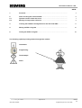
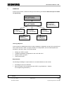
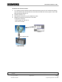
Automation and Drives - SCE
Training Document for Comprehensive Automation
Solutions
Totally Integrated Automation (T I A)
MODULE A5
Programming the CPU 314C-2DP
T I A Training Document
Issue date: 02/2008
Page 1 of 25
Module
A5
Programming the CPU 314C-2DP
Automation and Drives - SCE
This document has been written by Siemens AG for training purposes for the project entitled "Siemens
Automation Cooperates with Education (SCE)".
Siemens AG accepts no responsibility for the correctness of the contents.
Transmission, use or reproduction of this document is only permitted within public training and educational
facilities. Exceptions require the prior written approval of Siemens AG (Mr. Michael Knust
[email protected]).
Offenders will be liable for damages. All rights, including the right to translate the document, are reserved,
particularly if a patent is granted or utility model is registered.
We would like to thank the following: Michael Dziallas Engineering, the teachers at vocational schools, and all
others who helped to prepare this document.
T I A Training Document
Issue date: 02/2008
Page 2 of 25
Module
A5
Programming the CPU 314C-2DP
Automation and Drives - SCE
SEITE:
1.
Foreword ..............................................................................................................
4
2.
2.1
2.2
Notes on Using the CPU 314C-2DP ...................................................................
Operator Control of the CPU 31xC.....................................................................
Memory Concept of the CPU 31xC ....................................................................
6
7
9
3.
Creating the Hardware Configuration for the CPU 314C-2DP.........................
11
4.
Writing a STEP 7 Program ..................................................................................
21
5.
Testing the STEP 7 Program ..............................................................................
24
The following symbols provide guidance through this module:
Information
Programming
Task example
Notes
T I A Training Document
Issue date: 02/2008
Page 3 of 25
Module
A5
Programming the CPU 314C-2DP
Automation and Drives - SCE
1.
FOREWORD
In terms of its contents, module A5 belongs to the teaching unit entitled "Basic Principles of STEP
7 Programming'.
Basic Principles of
STEP 7 Programming
2 to 3 days
Module A
Further Functions of
STEP 7 Programming
2 to 3 days Module B
Plant Simulation
with SIMIT SCE
1 to 2 days Module G
Progamming
Languages
Industrial Field
Bus Systems
Process
Visualization
2 to 3 days Module C
2 to 3 days Module D
2 to 3 days Module F
Frequency Converter
at SIMATIC S7
2 to 3 days Module H
IT Communication
with SIMATIC S7
2 to 3 days Module E
Learning Objective:
In this module, the reader learns how to create a hardware configuration for the CPU 314C-2DP and
how to write and test a STEP 7 program. Based on the steps below, the A5-module explains the
procedure in principle, using a very brief example:
•
•
•
•
Setting up a STEP 7 project
Creating the hardware configuration for the 314C-2DP CPU
Writing a STEP 7 program
Testing the program
Requirements:
The following knowledge is a precondition for successful utilization of this module:
•
•
Knowledge in the use of Windows
Basic principles of PLC programming with STEP 7 (e.g. Module A3 – 'Startup'
PLC Programming with STEP 7)
Foreword
T I A Training Document
Issue date: 02/2008
Notes
Hardware configuration
Page 4 of 25
STEP 7 program
Testing
Module
A5
Programming the CPU 314C-2DP
Automation and Drives - SCE
Hardware and software needed
1
2
3
4
PC, operating system Windows 2000 Professional starting with SP4 /XP Professional starting
with SP1/Server 2003 with 600 MHz and 512 RAM, free hard disk memory approx. 650 to 900
MB, MS Internet Explorer 6.0
Software: STEP7 V 5.4
MPI interface for the PC (e.g. PC adapter for USB)
SIMATIC S7-300 PLC with the CPU 314C-2DP
Configuration example:
- Power supply unit: PS 307 2A
- CPU: CPU 314-2DP
2 STEP7
1 PC
3 PC Adapter USB
4 S7-300 with
CPU 314C-2DP
Foreword
T I A Training Document
Issue date: 02/2008
Notes
Hardware configuration
Page 5 of 25
STEP 7 program
Testing
Module
A5
Programming the CPU 314C-2DP
Automation and Drives - SCE
2.
NOTES ON THE USE OF THE CPU 314C-2DP
The CPU 314C-2DP is shipped with an integrated PROFIBUS DP interface and integrated
inputs/outputs.
The following PROFIBUS protocol profiles are available for the CPU 314C-2DP:
-
DP interface as master according to EN 50170.
DP interface as slave according to EN 50170.
PROFIBUS-DP (decentralized peripherals) is the protocol profile for connecting decentralized
peripherals/field units with very fast reaction times.
The addresses of the input and output modules of this CPU can be parameterized.
Due to the following performance data, this CPU is especially suitable for training purposes:
- 48 kByte RAM, load memory in the form of a plug-in MicroMemoryCard (MMC), 64 kByte to 4
MByte
- 8192 bytes DI/DO, including 992 bytes central
- 512 bytes AI/AO, including 248 bytes central
- 0.1 ms / 1 K commands
- 256 counters
- 256 timers
- 256 clock memory bytes
- 24 DIs, including 16 which can be used for integrated functions; all can be used as alarm inputs as
well
- 16 DOs, integrated; 4 of which are fast outputs
- 4 AIs for current/voltage, 1 AI resistor integrated
- 2 AOs for current/voltage, integrated
- 4 pulse outputs (2.5 kHz)
- 4-channel counting and measuring with 24 V (60 kHz) incremental encoders
- Integrated positioning function
Foreword
T I A Training Document
Issue date: 02/2008
Notes
Hardware configuration
Page 6 of 25
STEP 7 program
Testing
Module
A5
Programming the CPU 314C-2DP
Automation and Drives - SCE
2.1
OPERATING THE CPUS 31XC
Operator control and display elements
The following illustration shows the operator control and display elements of a CPU 31xC.
The arrangement and number of elements in some CPUs differ from this illustration.
The figures show the following
CPU elements:
(1) Status and error displays
(2) Slot for the Micro Memory Card (MMC),
incl. the ejector
(3) Connections of the integrated I/O.
(4) Power supply connection
(5) 1st interface X2 (PtP or DP)
(6) 1st interface X1 (MPI)
(7) Mode selector switch
The following illustration shows the digital and analog inputs/outputs integrated on the CPU.
The figure shows the following
integrated I/Os:
(1) Analog I/Os
(2) each with 8 digital inputs
(3) each with 8 digital outputs
(4) Front connectors (front
doors are open)
f
Foreword
T I A Training Document
Issue date: 02/2008
Notes
f
Hardware configuration
Page 7 of 25
STEP 7 program
Testing
Module
A5
Programming the CPU 314C-2DP
Automation and Drives - SCE
Status and fault/error displays
The CPU has the following LED displays:
Slot for the SIMATIC Micro Memory Card (MMC)
A SIMATIC Micro Memory Card (MMC) is used as a memory module for the CPU 31xC. The MMC
can be used as a load memory and as a transportable data carrier. The MMC must be plugged in
before the CPU can be operated because the CPUs 31xC do not have an integrated load memory.
Mode selector
The mode selector can be used to choose the current operating mode of the CPU. The mode
selector is designed as a toggle switch with 3 positions.
Positions of the mode selector
The positions of the mode selector are explained in the same sequence as they occur on the CPU:
Position
RUN
STOP
MRES
Foreword
T I A Training Document
Issue date: 02/2008
Description
RUN mode
STOP mode
Memory Reset
Notes
Comments
The CPU is processing the user program
The CPU is not processing a user program
Button position of the operating mode switch for a memory
reset of the CPU. A CPU memory reset requires a specific
operating sequence (refer to the Installation Manual,
Chapter Commissioning)
Hardware configuration
Page 8 of 25
STEP 7 program
Testing
Module
A5
Programming the CPU 314C-2DP
Automation and Drives - SCE
2.2
MEMORY AREAS OF THE CPU 31XC
Introduction
The memory of the CPU 31xC can be divided into three areas:
Note
Only with the MMC plugged in is it possible to load user programs and therefore operate the CPU
31xC
Load memory
The load memory is located on a SIMATIC Micro Memory Card (MMC).
Its size is exactly the same as that of the MMC. It is used for storing code blocks and data blocks as
well as system data (configuration, connections, module parameters, etc.).
Blocks that are marked as not being relevant to program execution are exclusively stored in the load
memory.
In addition, the complete planning data for a project can be stored on the MMC.
RAM
The RAM is integrated on the CPU and cannot be expanded. It is used for processing the code and
processing the data of the user program. The program is executed exclusively in the RAM and the
system memory.
Once the MMC has been plugged in, the RAM of the CPU is retentive.
System memory
The system memory is integrated on the CPU and cannot be expanded.
It contains
- the operands area for clock memories, timers and counters
- the process images of the inputs and outputs
- the local data
Foreword
T I A Training Document
Issue date: 02/2008
Notes
Hardware configuration
Page 9 of 25
STEP 7 program
Testing
Module
A5
Programming the CPU 314C-2DP
Automation and Drives - SCE
Retentivity
Your CPU 31xC has retentive memory. Retentivity is implemented on the MMC and on the CPU.
Due to this retentivity, the contents of the retentive memory are retained even after the mains supply
has been switched off and the CPU has been restarted (warm restart).
Load memory
You program in the load memory (MMC) is always retentive. During loading, it is stored on the MMC,
is powerfail-proof and cannot be cleared.
Work memory (RAM)
Your data in the work memory are backed up on the MMC in the event that the mains supply is
switched off. The contents of data blocks are therefore always retained.
System memory
With regard to clock memories, timers and counters, you configure (properties of the CPU,
Retentivity tab) which parts are to be retentive and which are to be initialized with "0" when the
system is restarted (warm restart).
The diagnostic buffer, MPI address (and baud rate) as well as the runtime meter are generally stored
in the retentive memory area on the CPU. The retentive area for the MPI address and the baud rate
ensure that your CPU is still able to communicate after a power failure, a complete memory reset or
loss of the communication parameters (because the MMC was removed, or the communication
parameters were deleted).
Retention of the memory objects
The following table shows which memory objects are retained when transitions between operating
modes occur.
Memory Object
Operating Mode Transition
X
X
X
STOP Æ
RUN
X
X
X
Memory
Reset
X
-
X
X
X
X
X
X
PowerOn/PowerOff
User Program/User Data (load memory)
Actual values of the DBs
Flags, timers and counters configured as
retentive
Diagnostic buffer, hours run meter
MPI address, baud rate
X = retentive; - = not retentive
Foreword
T I A Training Document
Issue date: 02/2008
Notes
Hardware configuration
Page 10 of 25
STEP 7 program
Testing
Module
A5
Programming the CPU 314C-2DP
Automation and Drives - SCE
3.
CREATING THE HARDWARE CONFIGURATION FOR THE CPU 314C-2DP
In Step 7, files are managed with the 'SIMATIC Manager'. Here, program blocks can be copied, for
example, or called for further processing with other tools by clicking on them with the mouse. Use of
the SIMATIC Manager is in line with the usual Windows standards (e.g. right-clicking on a
component causes its selection menu to appear).
In STEP 7, each project is created with a fixed specified structure. The programs are stored in the
following directories:
SIMATIC 300 stations:
Here, the corresponding
hardware configuration
data (Hardware/SC*1) and
CPU data are stored.
Project:
This directory contains the
hardware (e.g. SIMATIC 300
stations) and the subnets
(e.g. MPI and PROFIBUS).
Sources/SO*1:
Here, sources (e.g. SCL
sources) are stored which
can be changed into
executable programs through
conversion.
Blocks/APoff*1:
Here, the program blocks
( OB, FB, FC, SFB, SFC,
DB etc. ) are stored.
CPU:
Here, the S7
program and the
networked
connection partners
(Connections/CO*1)
are entered.
S7 Program:
Here, the user programs
(Blocks/AP off*1), symbol
tables (Symbols/SY*1) and
sources (Sources/SO*1) are
managed.
Symbols/SY*1:
Here, the symbol lists for
symbolic addressing are
stored.
*1 Designations from STEP 7 Version 2.x
Foreword
T I A Training Document
Issue date: 02/2008
Notes
Hardware configuration
Page 11 of 25
STEP 7 program
Testing
Module
A5
Programming the CPU 314C-2DP
Automation and Drives - SCE
The hardware configuration of the PLC is mapped in the 'SIMATIC 300 Station' and 'CPU' folders.
This is done in the special case where a configuration is created with the CPU 314C-2DP.
Also, a clock memory is configured and the addresses of the input and output modules are set in this
case.
The user must perform the following steps in order to set up a project and create the hardware
configuration.
1.
The central tool in STEP 7 is the 'SIMATIC Manager', which is started by double-clicking on the
icon. ( → SIMATIC Manager)
2.
STEP 7 programs are managed in projects. Such a project will now be set up ( → File → New)
Foreword
T I A Training Document
Issue date: 02/2008
Notes
Hardware configuration
Page 12 of 25
STEP 7 program
Testing
Module
A5
Programming the CPU 314C-2DP
Automation and Drives - SCE
3. The project is now assigned the name 'CPU314C_2DP' under 'Name' ( → CPU314C_2DP →
OK)
4.
A 'SIMATIC 300-Station' station is now inserted. (→ Insert → Station → SIMATIC 300 Station)
Foreword
T I A Training Document
Issue date: 02/2008
Notes
Hardware configuration
Page 13 of 25
STEP 7 program
Testing
Module
A5
Programming the CPU 314C-2DP
Automation and Drives - SCE
5.
Open the configuration tool by double-clicking on 'Hardware'. (→ Hardware)
6.
Open the hardware catalog by clicking on the
symbol. (→
)
The catalog is divided into the following directories:
- PROFIBUS-DP/PA, SIMATIC 300, SIMATIC 400 and SIMATIC PC Based Control and provides you with all the module racks, modules and interface modules for designing your
hardware configuration.
Foreword
T I A Training Document
Issue date: 02/2008
Notes
Hardware configuration
Page 14 of 25
STEP 7 program
Testing
Module
A5
Programming the CPU 314C-2DP
Automation and Drives - SCE
Insert a rail by double-clicking on 'Rail' ( → SIMATIC 300 → RACK-300
→ Rail).
7.
A configuration table for designing Rack 0 is then displayed.
Foreword
T I A Training Document
Issue date: 02/2008
Notes
Hardware configuration
Page 15 of 25
STEP 7 program
Testing
Module
A5
Programming the CPU 314C-2DP
Automation and Drives - SCE
8.
From the hardware catalog, you now can select any of the modules that are also plugged into
the real rack and insert them in the configuration table.
To do this, you must click on the name of the respective module, hold down the mouse button
and drag the module into a row of the configuration table using the Drag & Drop function.
We are starting with the power supply unit 'PS 307 2A'. (→ SIMATIC 300 → PS-300 → PS 307
2A)
Note: If your hardware differs from that shown here, just select the corresponding modules from the
catalog and insert them into your rack.
The order numbers of the individual modules are noted on the components and are also shown in
the footer of the catalog.
Foreword
T I A Training Document
Issue date: 02/2008
Notes
Hardware configuration
Page 16 of 25
STEP 7 program
Testing
Module
A5
Programming the CPU 314C-2DP
Automation and Drives - SCE
9.
In the next step, we drag the CPU 314C-2DP onto the second slot. When this is being done, the
order number and the version of the CPU can be read on the front of the CPU. (→ SIMATIC
300 → CPU-300 → CPU 314C-2DP → 6ES7 314-6CF00-0AB0).
10. In the following dialog box, we now want to set up the integrated PROFIBUS interface. Because
we will not use the interface here, we accept the settings with 'OK'( → OK ).
Note: Slot No. 3 is reserved for interface modules and therefore remains empty. Other modules
which are not interface modules (IM) are therefore placed on slots 4 to 11.
Foreword
T I A Training Document
Issue date: 02/2008
Notes
Hardware configuration
Page 17 of 25
STEP 7 program
Testing
Module
A5
Programming the CPU 314C-2DP
Automation and Drives - SCE
11. The properties of some modules can be altered
(→ Click on module→ Change properties → OK).
For example, a clock memory can be specified for all CPUs (→ Cycle/Clock memory → ∨ Clock
memory → Memory Byte 100).
Foreword
T I A Training Document
Issue date: 02/2008
Notes
Hardware configuration
Page 18 of 25
STEP 7 program
Testing
Module
A5
Programming the CPU 314C-2DP
Automation and Drives - SCE
12. With most S7-300 CPUs, the addresses of the I/O modules can be altered.
This is done by double-clicking on the corresponding modules and altering their settings in the
'Addresses' tab.
A note should always be made of these addresses (addresses assigned automatically are
usually tied to a specific slot). ( → DI24/DO16 → Addresses → Deselect System Default → 0
→ Deselect System Default → 0 → OK )
Foreword
T I A Training Document
Issue date: 02/2008
Notes
Hardware configuration
Page 19 of 25
STEP 7 program
Testing
Module
A5
Programming the CPU 314C-2DP
Automation and Drives - SCE
13. By clicking on the
and
buttons, the configuration table is now first stored and
converted, and then loaded into the PLC. When this is being done, the key switch on the CPU
should be in the Stop position! ( →
Foreword
T I A Training Document
Issue date: 02/2008
Notes
→
Hardware configuration
Page 20 of 25
)
STEP 7 program
Testing
Module
A5
Programming the CPU 314C-2DP
Automation and Drives - SCE
4.
WRITING A STEP 7 PROGRAM
We are writing the program to be tested in the statement list language (STL), and it only contains two
lines.
Here, the frequencies of the MB100 clock memory byte activated in the hardware are to be read out
on an output byte.
Assignment list:
MB100
AB0
Clock
AB
Clock memory byte
Display
A cycle duration/frequency is assigned to each bit of the clock memory byte. Assignment is as
follows:
Bit:
Clock duration (s):
Frequency (Hz):
7
2
0.5
6
1.6
0.625
5
1
1
4
0.8
1.25
3
0.5
2
2
0.4
2.5
1
0.2
5
0
0.1
10
14. In the 'SIMATIC Manager', mark the 'Blocks' folder.( → SIMATIC Manager → Blocks)
Foreword
T I A Training Document
Issue date: 02/2008
Notes
Hardware configuration
Page 21 of 25
STEP 7 program
Testing
Module
A5
Programming the CPU 314C-2DP
Automation and Drives - SCE
15. In the SIMATIC Manager, double-click on the 'OB1' block to open it ( → OB1)
16. As an option, you can enter the properties of the OB1 for documentation purposes and accept
them with 'OK'.
( →OK)
Foreword
T I A Training Document
Issue date: 02/2008
Notes
Hardware configuration
Page 22 of 25
STEP 7 program
Testing
Module
A5
Programming the CPU 314C-2DP
Automation and Drives - SCE
17.
'LAD/STL/FDB Program S7 Blocks’ is an editor which allows you to create your STEP
7 program as you require. To this end, the OB1 organization block with the first network has
already been opened. In order to create your first logic operations, you must mark the first
network. Now you can write your first STEP 7 program. Individual programs are usually divided
into networks in STEP 7. You open a new network by clicking on the network symbol,
.
Note: Comments regarding program documentation are separated from the program commands by
the characters "//".
The network
L
T
MB 100
AB 0
loads the clock memory byte activated in the hardware configuration and transfers it to an output
byte. As a consequence, the 8 bits of the output byte flash in the different frequencies of the clock
memory bits.
Note: The address of the output byte can be different from case to case, depending on the hardware
configuration.
Foreword
T I A Training Document
Issue date: 02/2008
Notes
Hardware configuration
Page 23 of 25
STEP 7 program
Testing
Module
A5
Programming the CPU 314C-2DP
Automation and Drives - SCE
5.
TESTING THE STEP 7 PROGRAM
The STEP 7 program to be tested can now be loaded into the PLC.
In our case, this is only OB1.
18. Save the organization block with
and load it into the PLC by clicking on
being done, the key switch on the CPU should be in the STOP position! ( →
Foreword
T I A Training Document
Issue date: 02/2008
Notes
Hardware configuration
Page 24 of 25
STEP 7 program
. When this is
→
)
Testing
Module
A5
Programming the CPU 314C-2DP
Automation and Drives - SCE
19. To start the program, move the key switch to the RUN position. Click on the
view the program in 'OB1'.
(→
Foreword
T I A Training Document
Issue date: 02/2008
symbol to
)
Notes
Hardware configuration
Page 25 of 25
STEP 7 program
Testing
Module
A5
Programming the CPU 314C-2DP