1
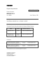
s
Program Library Karlsruhe
S79220-A0978-A-05-7637
Product Information
BRIDGE CS-L2
Var. V02.01
Issue: February, 1999
Descriptors
TELEPERM M , BRIDGE CS-L2 , UPGRADE , UPDATE
Summary
The present Product Information relates to the System Software Package:
Name
Variant
Product no. (MLFB)
BRIDGE CS-L2
V02.01
6DS2 510-0XX00-0XA0
BRIDGE CS-L2
upgrade/update
V02.01
V01.06
6DS2 510-0XX00-0XB1
Description:
Ergänzende Systemdoku. ASx88/TM Technische Beschreibung BRIDGE CS-L2
German
C79000-G8000-C700
Supplem. System Docu. ASx88/TM Technical Description BRIDGE CS-L2
English
C79000-G8076-C700
This manuals have to be ordered seperate if required.
© SIEMENS AG 1996-1999
Änderungen vorbehalten
Subject to alteration
Sous réserve de modications
Con riserva di modifiche
Product Information
BRIDGE CS-L2
1
February, 1999
Scope
The product information for the system software V02.00 remains valid. The following
information represents a supplement.
The delivery consists of:
6DS2 510-0XX00-0XA0
6DS2 510-0XX00-0XB1 (Upgrade/Update)
BRIDGE CS-L2 Memory Card
Diskette 3,5" with BRIDGE CS-L2 software
Diskette 3,5" with tools for installation
Diskette 3,5" with tools for installation
Software contract and registration card
Software contract
Product Information
Product Information
Note on software protection:
The memory card must be considered as part of the CPU. If the memory card is removed
during current operation, the BRIDGE CS-L2 enters STOP, as a result of the software
protection, i.e. telegrams are no longer processed.
Attention:
Before commissioning, please read the current documentation carefully.
Product Information
present document
Technical
Description
TELEPERM M Bridge CS-L2
Technical Description
C79000-T8076-C707
included in:
Supplementary System Documentation ASx88/TM
C79000-G8076-C700
Copyright © SIEMENS AG 1996-1999. All Rights Reserved.
S79220-A0978-A-05-7637
Page 2 of 20
Product Information
BRIDGE CS-L2
2
February, 1999
Commissioning
The Memory Card contains the entire system software for the Bridge (version V02.01) .
To perform an upgrade or update from diskette, a BRIDGE CS-L2 memory card must be
available.
The upgrade procedure is performed offline with a PC or a programming device having a
compatible MC interface (e.g. PG740).
The update procedure is performed either from the IBS terminal (online) or from a
programming device having a compatible MC interface (e.g. PG740).
A description of the upgrade procedure is provided under heading 2.2 in this document, of
the update procedure under heading 2.3 .
Caution:
The file RM3_PC1.SYS on the memory card must never be deleted, moved or
overwritten, as this would mean that the memory card would no longer be
bootable!
2.1 Startup by Commissioning Terminal
Additional the IBS-Tool diskette contains your local tool in the directory ASBEDIEN. Install
this on your PC to be used for commissioning of the BRIDGE CS-L2 according to the
installation instructions in the document file ASBEDI_E.DOC in the directory ASBEDIEN,
and connect your PC to the serial commissioning interface of your BRIDGE CS-L2 via a
serial interface.
For operation under Windows 3.1, a PIF file is delivered with the software. This contains
the following settings: run in full screen mode, exclusive foreground execution, foreground
priority very high.
For operation under Windows 95, the following setting should be specified: idle time
activity very low; no screen saver.
Using your "Commissioning terminal" installed in this manner and the commands of the
ASBEDIEN input program you can access all data on the memory card inserted in the
BRIDGE CS-L2.
Read the parameter files which have to be processed to enable parameterization from the
memory card into a file on your PC using the command "COPY_PC ...". You can modify
this file on your PC according to your system configuration using the ASCII editors which
can be executed under DOS, and then write them back onto your memory card using the
ASBEDIEN command "COPY_TM ...".
Note:
Before starting the UPGRADE/UPDATE activities, please ensure that a current backup of
any files that are to be modified exists. This will allow the previous software version to be
restored in the even of unforeseen circumstances. The files on the memory card are not
write protected, so care should be taken when accessing the memory card.
To back up the files from the memory card to your archive, use the ASBEDIEN command
"COPY_PC ...".
Copyright © SIEMENS AG 1996-1999. All Rights Reserved.
S79220-A0978-A-05-7637
Page 3 of 20
Product Information
BRIDGE CS-L2
February, 1999
2.2 Procedure for Upgrade to V02.01 with Programming Device PG740
Switch off the power supply of the BRIDGE CS-L2 before pulling the memory card!
For the upgrade, insert the memory card into the MEM-CARD slot of the PG740. Now start
the batch UPGRADE.BAT (if applicable, information on the memory card drive, default
setting is E:):
This batch file
- creates a directory C:\UPGRADE.201 (for this, at least 1 MByte must be free on drive
C:).
- copies all files from memory card into the upgrade directory.
- deletes the RMOS system file, as this can never be copied to the MC.
- deletes all BAK files.
- copies the packed upgrade files from disk into the directory (the system files to be
upgraded are then overwritten).
- reformats the memory card and sets up the RMOS system.
- copies all files from the upgrade directory to the memory card
Now perform the following two steps:
1) Put the upgraded memory card in the allocated Bridge CS-L2 and initiate a reboot of
the CPU (power on).
2) Install the new terminal program ASBEDIEN V1.06 to your PC from the diskette
included with your delivery (IBS tools).
Notes:
The upgrade batch runs under Windows 95 and 3.1, but not under Windows NT !
Subdirectories on the Memory Card will not be copied. These have to be saved to the PC/
Programming device bevor starting the upgrade procedure.
The upgrade directory is not deleted. This means that, if an error should occur during the
upgrade process, the process can be repeated.
Attention:
If more than one Bridge memory card are upgraded the directory
UPGRADE.201 must either be deleted or renamed between the individual
upgrade processes.
The upgrade directory can also be used as a backup copy of the entire system software.
This means that repairs can be carried out on memory cards with defective software
(create directory UPGRADE.200, copy backed up file to it and start the batch file).
Copyright © SIEMENS AG 1996-1999. All Rights Reserved.
S79220-A0978-A-05-7637
Page 4 of 20
Product Information
BRIDGE CS-L2
February, 1999
2.3 Procedure for Update V01.05 to V01.06
2.3.1 Update by Commissioning Terminal
You will find the files listed below in the directory A:\UPDATE.106 on the UPDATE diskette
delivered to you. Copy these files to the directory ‘C:\ASBEDIEN’ on your Commissioning
Terminal PC or into the current working directory (e.g. C:\TEMP is specified in
ASBEDIEN.PIF).
On the Commissioning Terminal PC connected to the BRIDGE CS-L2, start the program
ASBEDIEN.exe (via ASBEDIEN.PIF under Windows, so that the program runs in full
screen mode and without a screen saver).
Now, in command mode, copy the files previously backed up to the PC to the memory
card in the BRIDGE CS-L2 in the following sequence:
<ESC>COPY_TM
<ESC>COPY_TM
<ESC>COPY_TM
<ESC>COPY_TM
<ESC>COPY_TM
<ESC>COPY_TM
<ESC>COPY_TM
<ESC>COPY_TM
IBS_BEDI.386
STARTER.386
BRI_BEDI.386
BRIDGE.386
ITASK.EXE
RMOS.INI
L2AMPRO.INX
VERSION.TXT
resp.
resp.
<ESC>COPY_TM
C:\ASBEDIEN\IBS_BEDI.386
<ESC>COPY_TM C:\TEMP\STARTER.386
...
If necessary, the following file should be modified in accordance with this product
information.
BR_SYS.INI
settings for non-redundant operation of the CS 275 bus
After a successful transfer, exit ASBEDIEN (with Alt-X).
Now perform the following two steps:
1) Initiate a reboot of the BRIDGE CS-L2 (reset or off/on)
2) Install the new terminal program ASBEDIEN V1.06 to your PC from the diskette
included with your delivery (IBS tools).
Attention:
The data transfer was only successful if the command COPY_TM ends
without error messages, and without any manual intervention (e.g.
termination with ESC). In the case of errors, the copy procedure must be
repeated.
If problems occur during the data transfer (frequent terminations), we
recommend the following procedure:
• If the first file (IBS_BEDI.386) was transferred without errors, the BRIDGE
CS-L2 can be rebooted with the new emergency utility disk (press MRES
during switch-on). Together with the new ASBEDIEN V1.06, an error free
transfer can be expected.
• Before the next RESET, the files IBS_BEDI.386 and STARTER.386 must
be successfully transferred.
Copyright © SIEMENS AG 1996-1999. All Rights Reserved.
S79220-A0978-A-05-7637
Page 5 of 20
Product Information
BRIDGE CS-L2
February, 1999
2.3.2 Update by Programming Device PG740
Before starting the UPDATE activities (pulling the memory card), please ensure that a
current backup of any files that are to be modified exists. This will allow the previous
software version to be restored in the even of unforeseen circumstances.
Switch off the BRIDGE CS-L2 before pulling the memory card!
Copy the files listed under 2.3.1 from the update diskette into a new directory having the
'name' of your PG740.
For the update, insert the memory card into the MEM-CARD slot of the PG740. Now copy
all files from the directory 'name' onto the memory card (either using the file manager or
explorer, or using a DOS box):
COPY name\*.* E: /y
Now perform the following two steps:
1) Plug the upgraded memory card of the Bridge back into the allocated BRIDGE CS-L2
and initiate a reboot of the BRIDGE CS-L2 (reset or off/on).
2) Install the new terminal program ASBEDIEN V1.06 to your PC from the second
diskette included with your delivery (IBS tools).
3
Removed Errors (from V02.00 to V02.01)
F: Function concerned
A: Appearance
M: Modification
• F: Delay of telegram transport
A: Very sporadically within the Bridge it can happen, that telegrams were not passed
through immediatelly, but only when new telegrams were be added.
M: Immediate pass through of the received telegrams.
• F: Commissioning commands COPY_PC and COPY_TM
A: Both file transfer commands break off with error message.
M: Serial transmission corrected.
Copyright © SIEMENS AG 1996-1999. All Rights Reserved.
S79220-A0978-A-05-7637
Page 6 of 20
Product Information
BRIDGE CS-L2
February, 1999
3.1 Removed Errors (already with V02.00)
• F: Time synchronization
A: Time telegrams were not always transmitted at high priority. In exceptional
circumstances several time telegrams with different time data were transmitted
shortly after one another.
M: The throughput-time of time telegrams in the bridge was optimized.
• F: Behavior when switch set to STOP
A: In the STOP state, old telegrams were kept (e.g. several time telegrams at the
same time) and full receive buffers on the bridge's bus couplings caused the other
bus participants to repeatedly send messages unnecessarily.
M: Telegrams are no longer kept in the STOP state.
• F: Behavior when switch set to MRES (Soft-Reset)
A: This function caused the bridge to stop, which could then only be restarted with a
cold start.
M: Functions according to Table 4-1 of the technical description.
• F: Loss of telegrams during periods of high activity
A: Telegrams can be lost during periods of high activity when the target address
cannot accept the telegrams from the bridge quickly enough.
M: The reception part of the bridge is choked during periods of high activity. In this
way, the transmitter learns of the bridge’s coupling backlog and can, if necessary,
repeat the telegrams. This means that telegrams are no longer lost in this situation.
• F: Control of STOP LED when bus coupling errors occur
A: If the bridge recognizes a bus coupling error, it is reinitialized. This is indicated by
addressing the STOP LED, even if the bridge functions correctly afterwards.
M: If a bus coupling is successfully reinitialized due to an error, this event is signaled
by a flashing LED, either LED USR1 (for TPM478) or USR2 (for CP5412). This
condition is then terminated if the key switch is set to any other position.
• F: Behavior when switch set to RUN-P
A: No function was allocated to this setting in the technical description (Tab. 4-1).
It is, however, identical with the RUN setting.
M: Adaptation of the technical description
• F: Startup still occurs if configuration file is missing or configuration parameters are
incorrect
A: If certain configuration parameters are incorrect or the configuration file
BR_SYS.INI is missing, the bridge is started with the bus parameters BA=3 and
TA=20 without taking the existing network configuration into consideration.
M: The RUN LED flashes and the INTF LED (according to Table 4-1 of the technical
description) is continuously illuminated to indicate that the configuration parameters
are incorrect or missing.
Copyright © SIEMENS AG 1996-1999. All Rights Reserved.
S79220-A0978-A-05-7637
Page 7 of 20
Product Information
BRIDGE CS-L2
February, 1999
Caution:
When upgrading the bridge system software care must be taken that the bus coupling
module TPM478 is version 5 or later, otherwise all error corrections will not be effective.
4
Extended Functions
Installing the new M7 - CPU 486-3:
From V02.00, the BRIDGE system software runs not only on the CPU 488-4, but also on
the new CPU 486-3. The changes to the order configuration are described in detail in the
PLT 112 catalogue (1998 version).
The CPU 486-3 replaces the CPU 488-4. In contrast to the CPU 488-4, the CPU 486-3
has only two module ports for interface modules instead of three.
Caution:
A memory card upgraded from V01.03 to V01.05/V01.06 will not run on the
CPU 486-3. For this CPU, either an original delivery of V02.xx has to be
used, or an upgrade to V02.01 has to be done.
Replacing the CP5412-A1 with an IF964-DP interface module:
Now, not only the CP5412-A1 module (in the AT adapter card ATM 478) can be used as a
bus circuit for the PROFIBUS-TM system bus, but an IF964-DP interface module in an
EXM 478 extension module can also be used. The extended configuration is described in
Chapter 6.3 of this product information.
The configuration file L2AMPRO.INI (for the IF964) takes precedence over the parameter
file DOS_CONF.DAT (for CP5412-A1). In order to maintain the previous bus configuration
when updating, the new INI file is supplied as L2AMPRO.INX on the update diskette. The
file should be renamed accordingly if an IF964-DP is to be used. The file L2AMPRO.INI is
supplied as standard on the memory card with new deliveries of version V02.xx .
With new deliveries of version V02.xx, the PROFIBUS-TM system bus is accessed with
the interface module IF964-DP as standard, which is operated in the EXM 478 extension
module. This replaces the previous configuration with the CP5412-A1 bus coupling in the
ATM 478 extension module.
Copyright © SIEMENS AG 1996-1999. All Rights Reserved.
S79220-A0978-A-05-7637
Page 8 of 20
Product Information
BRIDGE CS-L2
February, 1999
4.1 Configuration of the BRIDGE CS-L2 with CPU 486-3 and IF964-DP
As the CPU 488-4 is replaced by the CPU 486-3 and the CP5412-A1 is replaced by the
IF964-DP interface module, there are the following alterations to the previous description
of the standard configuration.
EXM 478
with one IF964
Memory
Card
CPU 486-3
Power Supply
DC 24 V
System bus
PROFIBUS-TM
Service and
Diagnostic
Process control
monitoring
Slot
Module
box
1
2
-
3
Module
PS 407
Use for
Configuration
file
-
CPU 486-3
1
4
IF 961 - DIO
CPU 486-3
1
5
IF 962 - COM
IBS-Terminal
IF 964 - DP
System bus
PROFIBUS-TM
L2AMPRO.INI
-
CS275
BR_SYS.INI
EXM 478
1
6
Interface
Module
-
TPM 478
Copyright © SIEMENS AG 1996-1999. All Rights Reserved.
S79220-A0978-A-05-7637
Page 9 of 20
Product Information
BRIDGE CS-L2
February, 1999
4.2 Instructions on installing the CPU 486-3
• The hardware version of the CPU 486-3 must be at least 2. Earlier versions can cause
serious errors in the functions that use an interface module.
• When using the TPM 478 with a CPU 486-3, the CPU BIOS must be at least version
V2.07. This is guaranteed if hardware version 2 of the CPU 486-3 is used.
• When installing the new CPU 486-3 modules, the red INTF LED can illuminate for
several seconds during booting. This indicates that the BIOS has found a configuration
that does not agree with the last one saved. To stop this procedure, the data with the
configuration found by the BIOS when booting up must be saved. This can be achieved
when operating the machine for the first time in the following way (for further information
please refer to the SIMATIC S7 module manual):
a) Connect the terminal / hyper-terminal program to the COM1 port of the BRIDGE CSL2.
b) During booting of the BRIDGE CS-L2, press the Q key until the BIOS comes up.
c) Select the window with the system parameters
d) Leave the window with the system parameters, without making any changes.
e) Leave the BIOS setup with the SAVE option. This creates, among other things, a
new checksum of the BIOS data, the checksum is then saved in the module.
f) When the system is booted up in future, the INTF LED will not illuminate unless there
is a further CPU error.
• When booting up the Bridge CS-L2, the BIOS start-up of the CPU 486-3 lasts about 10
seconds. A criterion for this is that only the red STOP LED of the CPU 486-3 is lit. When
the operating system RMOS32 and the bridge system software are then subsequently
loaded, the green SD LED flashes or is lit continuously. If there is a significant delay
before the green SD LED illuminates, the BIOS settings can be changed to reduce the
BIOS start-up time. The following settings in particular should be implemented (for
further information please refer to the SIMATIC S7 - module manual /1/):
♦ SETUP page „Hard Disk“:
Switch off ‘Auto’ option
♦ SETUP page „Floppy/Card“:
Set drive A to MemCard
• With the BRIDGE CS-L2, the module slots on the CPU 486-3 must not be fitted with an
IF964 interface module. An IF964 module inserted here cannot be addressed by the
BRIDGE CS-L2 system software.
Copyright © SIEMENS AG 1996-1999. All Rights Reserved.
S79220-A0978-A-05-7637
Page 10 of 20
Product Information
BRIDGE CS-L2
5
February, 1999
Limited operating performance
No safety-relevant faults are currently known; the known faults are assigned to fault class
3 and lower.
• When using the load RAM function of PROGRAF AS+ by means of BRIDGE CS-L2 to
an AS x88/TM, the bus load setting must be limited to a maximum of 10 %.
• The Bridge buffers transactions that cannot be passed on directly to the receiver. Once
the connection is reestablished, the backlog of telegrams is caught up. Messages
transmitted in the catch-up period can have older time stamps.
• With PROFIBUS-TM, the transport of multi-address transactions is ensured by
PROFIBUS mechanisms. If a receiver of a multi-address transaction is not available, no
display task is generated.
Caution:
When working on initialization files (*.INI), tabs (09H) should not be used. Spaces (20H)
should be used instead. Failure to comply could lead to interpretation errors.
Note:
BRIDGE cannot start up if the parameter ADR in the initialization file BR_SYS.INI is not
set correctly.
In this case, BR_SYS must be parameterized by means of the emergency operation,
which is entered by switching the CPU off, holding the key switch to MRES and switching
the CPU back on.
ADR=C600
means that TPM 478 is inserted in slot 6 (standard setting)
ADR=C800
means that TPM 478 is inserted in slot 8
Copyright © SIEMENS AG 1996-1999. All Rights Reserved.
S79220-A0978-A-05-7637
Page 11 of 20
Product Information
BRIDGE CS-L2
6
February, 1999
Configuration of the bus connections
The parameters for the BRIDGE CS-L2 are set in the configuration files BR_SYS.INI,
DOS_CONF.DAT (or L2AMPRO.INI) and SYS_PAR.INI .
) Subsequent parameters for BRIDGE CS-L2 should be set individually. In doing
this you should ensure compatibility with the other bus participants.
DOS_CONF.DAT
resp.
L2AMPRO.INI
BR_SYS.INI
Remark
l2_ts=xx [dez]
BATA=yyxx [hex]
bus address BA
____
BATA=yyxx [hex]
yy = BA
xx = TA
yy = BA
xx = TA
range
____
RANGE=xx [hex]
l2_hsa=xx [dez]
____
of all stations at the
PROFIBUS-TM
____
REDUNDANZ=x
x = 1: redundant
x = 0: non redundant
station address TA
highest station address
CS275 redundancy
Bridge filter
If the coupling module CP5412-A1 is used for the PROFIBUS-TM (SINEC L2) system bus,
the DOS_CONF.DAT initialization file must be used (see Chapter 6.2).
If, however, the IF964-DP interface module is used, the L2AMPRO.INI initialization file
must be used (see Chapter 6.3).
Copyright © SIEMENS AG 1996-1999. All Rights Reserved.
S79220-A0978-A-05-7637
Page 12 of 20
Product Information
BRIDGE CS-L2
February, 1999
6.1 Parameter of configuration file BR_SYS.INI
Parameter ADR=xxxx
Address of the Dual-Port-RAM of the TPM 478
C600 = standard system setting (hexadecimal)
Parameter DPR=xx
Address of the register of the TPM 478
C8 = standard system setting (hexadecimal)
Parameter RANGE=xx
Address range of all PROFIBUS-TM stations, which are
coupled over the BRIDGE CS-L2
Permissible range: 1-20 (hexadecimal)
Standard system setting: 20 (hexadecimal)
Parameter BATA=xxxx
Definition of the CS address of the BRIDGE in
hexadecimal representation
High byte: Bus No. BA (hexadecimal)
Low byte:
Station No. TA on CS275 bus resp.
PROFIBUS-TM (hexadezimal)
Parameter REDUNDANZ=x
Redundancy operating mode of CS275 bus
x = 1: Redundancy on CS275 long-distance bus
(Standard)
x = 0: No redundancy on CS275 long-distance bus
Examples of standard system settings:
TA = 32, BA= 0, Range = 32, TPM478 Slot = 6, REDUNDANZ = 1
____________________________________________________
ADR=C600
DPR=C8
RANGE=20
BATA=0020
REDUNDANZ=1
____________________________________________________
Note:
• The BATA must be set individually for each application. BRIDGE cannot start up with
the default factory setting.
• The range is set to its maximum size, i.e. 20h.
• The parameters ADR and DPR correspond to the standard settings of BRIDGE CS-L2.
In case you change these parameter, knowledge about the slot addresses of SIMATIC
M7 is required since incorrect entries can lead to serious system errors.
• If the ‘REDUNDANZ’ parameter is missing in the configuration file, the CS275 bus will
operate redundantly.
Copyright © SIEMENS AG 1996-1999. All Rights Reserved.
S79220-A0978-A-05-7637
Page 13 of 20
Product Information
BRIDGE CS-L2
February, 1999
6.2 Parameter of configuration file DOS_CONF.DAT for CP5412-A1
The configuration file DOS_CONF.DAT includes the PROFIBUS-TM bus parameters.
A specification of slot coordinates is not necessary.
Bus parameters:
Parameter
l2_ts =
Station No. on PROFIBUS-TM (decimal representation)
Default setting: 32
Must be identical to the station address in BATA from
BR_SYS.INI. If different addresses are entered, the
parameter 'l2_ts' from DOS_CONF.DAT is used.
Note: The station addresses should be assigned without gaps
if possible. This may increase the performance.
Parameter
l2_hsa =
Highest station address on PROFIBUS-TM
(decimal representation)
Default setting: 32
Note: If the actual highest station address is entered exactly,
this may increase the performance. However, to retain
a reserve, it is also advisable when configuring to set a
higher station address than that actually present.
Parameter
l2_ttr =
Token rotation time (decimal representation)
Default setting: 90000
The default setting applies to a maximum of 10 active stations
on the PROFIBUS-TM bus. If more than 10 stations are present
on the PROFIBUS-TM bus, the parameter must be calculated
according to the following equation and entered:
l2_ttr = 9000 * [number of active PROFIBUS-TM stations].
Note: The factor 9000 in the equation only applies to a baud
rate of 1.5 MBaud.
All bus parameters are matched to a transmission rate of 1.5 MBaud.
Optimization requires detailed knowledge of the PROFIBUS standard, Part 1, DIN 19245.
Selection of a different transmission rate is illegal, and may result in faulty functioning.
The bus parameters are described in the SINEC Manual
TF5412/MS-DOS, WINDOWS (C79000-G8976-C031).
Attention: Apart from the bus parameters, the configuration file DOS_CONF.DAT also
contains system parameters for handling BRIDGE CS-L2 communication tasks.
Unauthorized modifications to these usually result in major faults in the BRIDGE
CS-L2.
Note:
The BUS address (BA) cannot be configured in DOS_CONF.DAT .
Copyright © SIEMENS AG 1996-1999. All Rights Reserved.
S79220-A0978-A-05-7637
Page 14 of 20
Product Information
BRIDGE CS-L2
February, 1999
Example of a configuration file DOS_CONF.DAT:
___________________________________________________
# FILE FOR INSTALLING TF/IHI DRIVER
# INSTTOOL VERSION = V 2.20 02.11.93
numboards = 1
boardtyp = 5412
SCP_device = CP_L2_1:
l2_hsa =
l2_ts =
l2_physical_layer = 0
l2_lock_sap = NONE
num_channel = 4
numproc = 2,5,5,0
channel_name = ADM,IHI,FLC,SCP
channel_type = SCP,IHI,IHI,SCP
element_size = 384
numhostbuffer = 2,75,75,2
numboardbuffer = 2,1,1,2
dpram_adr = 0xD0000
dpram_size = 0x10000
l2_station_type = 1
l2_baud_rate = 7
l2_medium_red = 0
l2_retry_ctr = 1
l2_default_sap = 10
l2_network_connection_sap = 37
l2_tsl = 3000
l2_tqui = 0
l2_tset = 240
l2_max_tsdr = 980
l2_min_tsdr = 150
l2_ttr =
l2_g = 30
l2_in_ring_desired = 1
int_vector = 12
server_id = CPADMI
window_size = 8
Download = \FW5412
Vendor = SIEMENS
HW_device = PC
___________________________________________________
To be set installation specific:
l2_ts=
real station address
default: l2_ts= 32
l2_hsa=
highest station address at segment
default: l2_hsa = 32
l2_ttr =
90000 for 2 to 10 active stations;
9000 x [number of active stations] for 11 to
32 stations (max. l2_ttr = 288 000)
default: l2_ttr = 90000
Copyright © SIEMENS AG 1996-1999. All Rights Reserved.
S79220-A0978-A-05-7637
Page 15 of 20
Product Information
BRIDGE CS-L2
February, 1999
The parameter assignments 'int_vector=12' and 'dpram_adr=0xD0000', with which the
interrupt and DPRAM address range are set, agree with the default settings of the bridges
and the DIP switches on the interface module CP5412-A1 which are already factory-set
when delivered.
Caution:
If the L2AMPRO.INI configuration file is also saved on the memory card, this configuration
takes precedence, i.e. a parameter file DOS_CONF.DAT existing in parallel and a bus
circuit CP5412-A1 are ignored.
6.3 Parameter of configuration file L2AMPRO.INI for module IF964-DP
1) 1) Parameters for slot addressing
Parameter slot =
Slot No. according to incrementing of SIMATIC M7-400
System setting: 5
Parameter modulbox = Module slot No. according to incrementing of SIMATIC M7-400
System setting: 1
The settings which correspond to the standard system configuration have been
preselected for the coordinates of the IF964-DP and should therefore be used unchanged.
Any changes to these parameters require knowledge of the slot addressing for SIMATIC
M7, and incorrect entries may result in major system faults.
2) Bus parameters
Parameter
l2_ts =
Station No. on PROFIBUS-TM (decimal representation)
Must be identical to the station address in BATA from
BR_SYS.INI . If different addresses are entered, the
parameter 'l2_ts' from L2AMPRO.INI is used.
Note: The station addresses should be assigned without gaps
if possible. This may increase the performance.
Parameter
l2_hsa =
Highest station address on PROFIBUS-TM
Default setting: 32
Note: If the actual highest station address is entered exactly,
this may increase the performance. However, to retain
a reserve, it is also advisable when configuring to set a
higher station address than that actually present.
Parameter
l2_ttr =
Token rotation time (decimal representation)
Default setting: 90000
The default setting applies to a maximum of 10 active stations
on the PROFIBUS-TM bus. If more than 10 stations are present
on the PROFIBUS-TM bus, the parameter must be calculated
Copyright © SIEMENS AG 1996-1999. All Rights Reserved.
S79220-A0978-A-05-7637
Page 16 of 20
Product Information
BRIDGE CS-L2
February, 1999
according to the following equation and entered:
l2_ttr = 9000 * [number of active PROFIBUS-TM stations].
Note: The factor 9000 in the equation only applies to a baud
rate of 1.5 MBaud.
All bus parameters are matched to a transmission rate of 1.5 MBaud.
Optimization requires detailed knowledge of the PROFIBUS standard, Part 1, DIN 19245.
Selection of a different transmission rate is illegal, and may result in faulty functioning.
Example of a configuration file L2AMPRO.INI:
# ****************** Start L2AMPRO - INI file ********************
#
--->
for
Bridge CS-L2 (PROFIBUS)
<---
# ****************** IF964 parameters ****************************
boardtyp
= IF964
slot
= 5
modulbox
= 1
# ****************** L2 bus parameters ***************************
l2_ts
= 32
l2_hsa
= 32
l2_baud_rate
= 7
l2_tsl
= 3000
l2_tqui
= 0
l2_tset
= 240
l2_max_tsdr
= 980
l2_min_tsdr
= 150
l2_ttr
= 90000
l2_g
= 30
# ****************** End L2AMPRO - INI file **********************
Caution:
If the bus circuit CP5412-A1 is connected in parallel to the IF964-DP module, the duplicate
interrupts can lead to serious system errors.
Copyright © SIEMENS AG 1996-1999. All Rights Reserved.
S79220-A0978-A-05-7637
Page 17 of 20
Product Information
BRIDGE CS-L2
February, 1999
6.4 Parameter of configuration file SYS_PAR.INI
The configuration file SYS_PAR.INI includes the parameter for inverting of the DIOIn/Outputs.
If the file SYS_PAR.INI is not present, the operation system uses the default settings from
file SYS_PAR.DEF.
Parameter DIO_MASKE_EIN=xxx
000: Inputs not negated
255: Inputs negated
Parameter DIO_MASKE_AUS=xxx
000: Outputs not negated
255: Outputs negated
___________________________________________
# System parameters 10.05.96
[ID = 99999999
Note: Your Bridge serial number
# DIO settings all inputs and outputs inverted
[DIO
DIO_MASKE_EIN =255
DIO_MASKE_AUS =255
[SCHL
S 0000 1111 2222 3333
#End
_______________________________________________________________________
Copyright © SIEMENS AG 1996-1999. All Rights Reserved.
S79220-A0978-A-05-7637
Page 18 of 20
Product Information
BRIDGE CS-L2
7
February, 1999
Connector Pin Assignment IF961-DIO
Following I & C Signals are available on IF961-DIO module:
Function Assignment of the Outputs
Output
Pin
Root
0V
Signalling output
Use
Remark
10
13
Common I & C signal
Cabinet lamp
max. 100 mA
Remark
DO 0
DO 1
DO 2
DO 3
DO 4
DO 5
DO 6
DO 7
Function Assignment of the Inputs
Input
Pin
Root
+24V
Signalling input
Use
19
17
Door contact
Door contact
DI 0
DI 1
DI 2
DI 3
DI 4
DI 5
DI 6
DI 7
Copyright © SIEMENS AG 1996-1999. All Rights Reserved.
S79220-A0978-A-05-7637
Page 19 of 20
Product Information
BRIDGE CS-L2
8
February, 1999
Status display and error messages
• The lamp test (all LEDs on) is not activated when switching on the network, but only
with master-reset and soft-reset.
• If the memory card is pulled during operation, after one minute, the bridge functionality
can no longer be guaranteed. This is signaled by a flashing STOP LED and the LED
USR1.
• If the BRIDGE CS-L2 recognizes an error in the bus coupling TPM478, the bus coupling
is automatically reinitialized and the LED USR1 flashes rapidly. If reinitialization is
successful, the RUN LED is continuously illuminated, while a more persistent error is
indicated by the STOP LED. Moving the key switch in any way (e.g. from RUN to RUNP or vice versa) will cancel the flashing LED USR1.
• If the BRIDGE CS-L2 recognizes an error in the bus coupling CP5412 A1, the bus
coupling is automatically reinitialized and the LED USR2 flashes rapidly. If reinitialization
is successful, the RUN LED is continuously illuminated, while a more persistent error is
indicated by the STOP LED. Moving the key switch in any way (e.g. from RUN to RUNP or vice versa) cancels the flashing LED USR2.
9
Operational modes switch (key switch)
• The switch setting RUN-P is functionally identical to the setting RUN.
• In the STOP operational mode (key switch setting), the coupling via the BRIDGE CS-L2
is interrupted. The couplings for the PROFIBUS-TM and for the CS275 continue to
participate in the token circulation and indicate this through the display on the front
plate. In this mode, messages can get lost on the BRIDGE CS-L2.
• In the case of a soft reset, all messages in the buffer are deleted and the bus couplings
TPM478 and CP5412-A1 or. IF964-DP are reset. Afterwards, communication is
restarted by initializing the bus couplings TPM478 and CP5412-A1 or IF964-DP. In
addition, a LED lamp test is carried out.
Copyright © SIEMENS AG 1996-1999. All Rights Reserved.
S79220-A0978-A-05-7637
Page 20 of 20