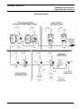
1
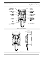
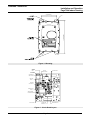
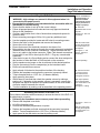
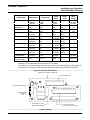
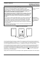
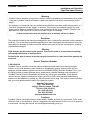
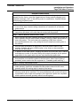
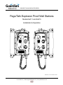
Industrial Communications Worldwide
Page/Talk Explosion Proof Wall Stations
Models ExP-1 and ExP-5
Installation & Operation
P005223 Rev. G 070718 7/19/2007 2:28 PM
7552 - 10th Ave. N.E. Calgary Alberta, Canada T2E 8W1
Ph: 403.258.3100 \ email:[email protected] \ www.guardiantelecom.com
Guardian Telecom Inc.
Installation and Operation
Page/Talk Indoor Housing
Table of Contents
Package Contents .................................................................................2
Overview ...............................................................................................3
Features ................................................................................................3
Installing the ExP-1/-5 ...........................................................................6
Accessing the Interior of the ExP-1/-5 ...................................................6
Group Muting.........................................................................................8
Ambient Noise Level Adjustment ..........................................................9
Operating the ExP-1 Single Line Station ...............................................9
Operating the ExP-5 Multi Line Station .................................................9
Troubleshooting...................................................................................10
Engineering Specifications ..................................................................11
Warranty ..............................................................................................12
Disclaimer............................................................................................12
Warning ...............................................................................................12
Service Telephone Number.................................................................12
Feedback.............................................................................................12
Guardian Product Return ....................................................................13
Page/Talk System Models and Options ..............................................14
Typical Installation ...............................................................................15
Table of Figures
Figure 1 - ExP-1/-5 Features .................................................................4
Figure 2 - ExP-1/-5 Dimensions ............................................................4
Figure 3 - Mounting ...............................................................................5
Figure 4 - Circuit Board Layout..............................................................5
Figure 5 - Electrical Connections...........................................................7
Figure 6 - Wiring ....................................................................................7
Package Contents
One (1) ExP-1 or ExP-5 Page/Talk Wall Station
Twelve (12) Faceplate Bolts
Two (2) Tubes of Lubricant
One (1) Installation & Operation Manual
Page 2
Guardian Telecom Inc.
Installation and Operation
Page/Talk Indoor Housing
Overview
ExP-1/-5 Explosion Proof Page/Talk Wall Stations
Guardian's Page/Talk Systems provide reliable and easy to use paging and communication within
industrial environments such as plants, mills and factories. Individuals can be paged from any
station and two or more persons can communicate on any available Talk line.
The Models ExP-1 (Single-line) and ExP-5 (Multi-line) stations described in this manual are designed
for use in Class I & II, Division 1 hazardous locations. Each ExP-1/-5 Wall Station provides up to
twelve watts of paging power for an external loudspeaker. A push button switch on the faceplate
puts the station into paging mode.
In order to avoid acoustical feedback from a loudspeaker receiving a signal from the station, a jumper
on the circuit board provides for the speaker to be muted when the Page button on the faceplate is
pressed. Group muting is also available for the same purpose, this feature mutes adjoining speakers
when the page button on any station in the group is pressed.
Guardian's Page/Talk stations and related equipment are compatible with systems provided by most
other manufacturers.
Features
Enclosure and Faceplate
• copper free cast aluminum - powder coated
Ambient Noise Monitor
• monitors the ambient noise and adjusts speaker volume accordingly
Connectors
• removable screw and plug Combicon connectors allow for ease of
installation, simply screw wires into plug and reinsert plug into PCB
socket
Page Switch
• page switch on faceplate of enclosure
Handset
• noise canceling microphone
• electronic hook switch provides durability
Headset
• optional plug in headset
Controls
• speaker volume
• ambient noise level
• microphone gain
• receiver volume
• side tone adjustment
Page 3
Guardian Telecom Inc.
Installation and Operation
Page/Talk Indoor Housing
1" NPT
ENTRANCE
FOR SPEAKER
CONNECTION
HANDSET/HEADSET
CORD CONNECTOR
Figure 1 - ExP-1/-5 Features
8.7 [ 221mm ]
10.0 [ 254mm ]
15.7 [ 399mm ]
6.0 [152mm ]
Figure 2 - ExP-1/-5 Dimensions
Page 4
Guardian Telecom Inc.
Installation and Operation
Page/Talk Indoor Housing
7.25 [184mm ]
Ø.4
14.67 [ 373mm ]
ENTRANCE
Figure 3 - Mounting
J3 FROM
HANDSET
RX/TX
J5 FROM
HOOK SWITCH
SPEAKER MUTE
J10 FROM
MICROPHONE
TRANSMITTER
LEVEL ADJUST
SIDE TONE
ADJUST
RECEIVER
LEVEL ADJUST
SPEAKER LEVEL
ADJUST
AMBIENT NOISE
MONITOR ADJUST
PUSH TO PAGE
J7 FROM PAGE
LINE SWITCH
MAIN CONNECTOR
Figure 4 - Circuit Board Layout
Page 5
Guardian Telecom Inc.
Installation and Operation
Page/Talk Indoor Housing
Installing the ExP-1/-5
•
•
•
•
•
•
•
•
•
•
•
•
•
•
•
•
•
•
•
•
WARNING - high voltages are present in this equipment when it is
connected to the power source.
Ensure that the location is non-hazardous before proceeding with any
installation or electrical wiring.
Ensure that the station is set up for the correct voltage.
Follow all appropriate electrical codes and use only approved electrical
fittings for the installation.
Choose a wall location that is free of obstructions and permits space for
conduit or wire.
Ensure mounting can support 30 lbs./14 kg and any additional load.
Use the template provided to locate and drill holes for mounting screws.
Remove the bolts on the faceplate and remove the faceplate.
Secure the unit to the wall.
Ensure that none of the electrical connection circuits are live.
Bring cable(s) into the enclosure through the conduit entrance(s) and attach
individual wires to the Combicon connector(s). Attach the wires from the
first or only cable to the bottom connector. Make Talk channel connections
to terminals 1A and 1B for the single line ExP-1. Plug any unused cable
entrances.
If the station is part of a Group Muting series connect the wires assigned to
this function to either the Mute or Park terminal on the connector.
Set the speaker mute jumper on the circuit board to the desired position.
Plug the connector(s) into the receptacle(s) on the interface board.
Ensure all connections are secure.
Apply a bead of lubricant to the machined surface of the housing.
Replace the faceplate ensuring that the connector is properly seated.
Torque faceplate bolts to 13.5 ft. lbs. (18 Newton-Meters).
Apply power to the system.
Wait at least 20 seconds then check the speaker volume by making a
paging call. If alteration to the speaker volume is necessary, remove the
faceplate and adjust the speaker level potentiometer on the circuit board –
clockwise rotation increases the volume.
Test the installation by making a call as described in the operating section.
Caution: Installation or
electrical wiring in a
hazardous location
could result in serious
injury to personnel or
damage to property.
Tip: check the
identification label on the
faceplate.
See:Figure 2 - ExP-1/-5
Dimensions
Note: Be careful when
removing the faceplate.
The circuit board is on
the faceplate.
See: Figure 4 - and
Figure 5 - Electrical
Connections
See: Group Muting
Tip: The lubricant acts
as a seal to prevent
water and dust from
entering the enclosure.
Note: Adjust speaker
volume while ambient
noise at the station is at
a minimum.
See: Figure 6 - Wiring
Accessing the Interior of the ExP-1/-5
Follow these instructions when necessary to access the interior of the ExP-1/-5
for adjustments or repairs.
• Declassify the hazardous area or remove power before proceeding.
• Remove the faceplate cover bolts.
• Lift off the faceplate cover.
• Perform the necessary adjustments or repairs.
•
•
Replace the faceplate and bolts ensuring that the connector is properly
seated. Torque faceplate bolts to 13.5 ft. lbs. (18 Newton-Meters).
Apply power to the wall station and test by making a call.
Page 6
See: Figure 1 - ExP-1/-5
Features
Note: Be careful when
removing the faceplate.
The circuit board is on
the faceplate.
Guardian Telecom Inc.
Installation and Operation
Page/Talk Indoor Housing
Assignment
System Power
Ambient Noise
Microphone
Speaker
Page Line
Channel
Designation
J4A/J5A
J4A/J5A
J4A/J5A
J6A
J6A
J7A
J7A
J2A/J3A
J2A/J3A
J2A/J3A
J2A/J3A
J2A/J3A
J2A/J3A
J2A/J3A
J2A/J3A
J2A/J3A
J2A/J3A
J2A/J3A
J2A/J3A
J2A/J3A
J2A/J3A
Description
HOT
COM
GND
MIC +
MIC SPK +
SPK PA Page Line
PB
"
1A Channel 1
1B
"
2A Channel 2
2B
"
3A Channel 3
3B
"
4A Channel 4
4B
"
5A Channel 5
5B
"
Mute
Park
Jacket
Color
Black
White
Green
n/a
n/a
n/a
n/a
Blue
Red
Red
L. Brown
Violet
L. Brown
Blue
L. Brown
Brown
L. Brown
Yellow
L. Brown
Stripe
Color
n/a
n/a
n/a
n/a
Red
Blue
Red
Violet
Blue
Brown
Yellow
Group Muting of
Orange
Loudspeakers
Spare Conductor
n/a
Extra
Red
(Special Order)
Note:
Channels 2 to 5 connections remain empty for ExP-1 hookup.
Wire
Gauge
14 AWG
14 AWG
14 AWG
n/a
n/a
n/a
n/a
18 AWG
"
18 AWG
"
18 AWG
"
18 AWG
"
18 AWG
"
18 AWG
"
18 AWG
12 AWG
If this station is in a Group Muting series, but is not to be muted when paging calls are made from
other stations in the group, connect the wires assigned to this function to the Park terminals.
Figure 5 - Electrical Connections
MAIN CIRCUIT BOARD CONNECTOR
MAIN CONNECTOR
J7A EXTERNAL SPEAKER
SPEAKER FUSE
0.5A/250V
GDA
POWER SUPPLY FUSE
(SEE SPECIFICATIONS)
Figure 6 - Wiring
Page 7
J2A/J3A IN/OUT
PAGE AND TALK CHANNELS
Guardian Telecom Inc.
Installation and Operation
Page/Talk Indoor Housing
Group Muting
In order to avoid acoustical feedback it may be desirable in certain
circumstances to mute speakers associated with adjoining stations when
making a paging call. This can be accomplished by interconnecting the “Group
Mute” terminals of each station in the group, and setting the speaker mute
jumpers on the circuit boards to the appropriate position.
See: Figure 5 - Electrical
Connections
Note: Putting the mute jumper of a station in the on position will mute the
associated speaker when the page button is pressed. If the jumper is in
the off position the speaker will not be muted when the page button is
pressed.
If group muting is used the associated speaker of any station in the group with
its mute jumper in the on position will be muted when a paging call is made
from any station in the group, including the associated station. Any speaker
associated with a station with its mute jumper in the off position will not be
muted when a paging call is made from any station in the group, including the
associated station.
Note: Paging calls
originating from stations
outside the group will be
heard regardless of the
position of the Mute
jumper.
If it is desired to bypass a station in a group, connect the group paging wires to
the PARK terminals of that station.
EXAMPLE OF GROUP MUTING
STATION "A"
STATION "C"
STATION "B"
ON
MUTE
JUMPER
OFF
MUTE
PARK
GROUP MUTE
SIGNAL CONDUCTORS
If the Group Mute Signal Conductors of station “B” are attached to the Park terminals, that station will
be bypassed and paging from stations “A” or “C” or any other station in the system will always be heard
over the loudspeaker associated with Station “B”, regardless of the position of the Mute jumper.
If the Group Mute Signal Conductors of station “B” are attached to the Mute terminals the condition of
the loudspeaker associated with that station will depend on the setting of the Mute On/Off jumper. If
the jumper is in the ON position the loudspeaker will be muted if a paging call is made from any of the
three stations. If the jumper is in the OFF position the paging call will not be muted if a paging call is
made from any of the three stations.
Paging calls from outside the Group will always be heard, regardless of the position of the mute jumper.
Page 8
Guardian Telecom Inc.
Installation and Operation
Page/Talk Indoor Housing
Ambient Noise Level Adjustment
The Ambient Noise Sensor on Guardian's Page/Talk stations automatically adjusts the
volume of the associated loudspeaker up to 10dB, so that pages can be heard over the
background noise.
See: Figure 4 - Circuit
There are two controls on the circuit board to adjust the Ambient Noise Sensor
Board Layout
mechanism. The Paging Speaker Volume Control – which is accessible from the back of
the module – sets the volume of the speaker to a comfortable level when the ambient
noise is at a minimum. The Ambient Noise Monitor Adjustment Control determines how
the speaker volume tracks the ambient noise. That is if the speaker is not loud enough
with a high ambient noise the control can be adjusted to increase the volume.
Alternatively if the speaker is too loud with a high ambient noise the control can be
adjusted to decrease the volume. It is usually not necessary to change the setting of the
Ambient Noise Monitor Adjustment Control since it is set at the factory for average
conditions. Adjustment could be necessary if for some reason the Ambient Noise
Sensor Microphone is shielded from the source of ambient noise or some similar
situation exists.
Operating the ExP-1 Single Line Station
Note: There is one talk
line on the ExP-1.
Initiating a Call
•
•
Remove the handset.
Ensure that the line is free.
Broadcasting a Page
•
•
Press and hold the Page button on the handset.
Broadcast the page. (e.g. "Joe, I need to talk to you, pick up a handset.")
Connecting with a Second Party
•
When the second party picks up their handset, both parties are connected and can
carry on a conversation.
Freeing the Line
•
Note: Continue holding
down the Page button
while broadcasting the
page.
Note: The second party
can be located at any
other station.
Place the handset back on the cradle.
Operating the ExP-5 Multi Line Station
Note: There are five
talk lines on the
ExP-5.
Initiating a Call
•
Remove the handset.
•
Select a free line using the Line selector.
Broadcasting a Page
•
•
Press and hold the Page button on the handset.
Broadcast the page that includes the number of the line you are using. (e.g. "Joe,
talk to me on line one.")
Note: Continue holding
down the Page button
while broadcasting the
page.
Connecting with a Second Party
•
When the second party selects the appropriate channel and picks up their handset,
both parties are connected and can carry on a conversation.
Freeing the Line
•
Place the handset back on the cradle.
Page 9
Note: The second party
can be located at any
other station.
Guardian Telecom Inc.
Installation and Operation
Page/Talk Indoor Housing
Troubleshooting
Note: If access to the interior of the ExP-1/-5 is required refer to the
appropriate section.
See: Accessing the Interior of
the ExP-1/-5
Station Is Dead But Associated Speaker Is Working
•
No repair possible, return station for repair.
Station Is Dead And Associated Speaker Is Not Working
•
•
Ensure power is being supplied to the station.
Check the fuse located on the connector board and replace if
necessary. Correct the problem that caused the fuse to fail.
See: Warranty and Product
Return
See: Engineering Specifications
for correct fuse rating
Handset Microphone Volume Too Low
•
Adjust TX level control on circuit board.
Handset Receiver Volume Too Low
•
Adjust RX level control on circuit board.
Feedback Or Distortion
•
•
Adjust sidetone level control on circuit board.
Inspect the line and connections for shorts and grounds.
Sidetone
•
Adjust sidetone level control on circuit board.
Station Stays On or Off Hook
1. Ensure power is being supplied to the station.
2. Test the proximity switch in the handset receiver cradle by
moving a small, permanent magnet over the area while listening on
the handset for the line to open and close.
3. If the movement of the magnet switches the on/off hook
condition, the magnet in the receiver cartridge of the handset may
be weak – try another handset. It is not necessary to wire in the new
handset to perform this test – if the new handset switches the on/off
hook condition, replace the existing handset with the new unit.
4. If the movement of the magnet does not appear to switch the
on/off hook condition the handset itself may be defective – try
another handset.
5. If these remedies do not correct the problem return the station
for repair.
Excessive Noise on Line
•
Verify no other station's handset is off the hook.
Crosstalk
•
Inspect wire terminations for crossed wire pairs.
Page 10
See: Warranty and Product
Return
Guardian Telecom Inc.
Installation and Operation
Page/Talk Indoor Housing
Engineering Specifications
ELECTRICAL REQUIREMENTS
INPUT VOLTAGE
20 - 26 / 90-140 / 200-260 VAC, 24 - 30VDC
INPUT FREQUENCY
50/60HZ
INPUT VOLTAGE/CURRENT/FUSE
120VAC/0.1AMP/0.5A 20MM CERAMIC FAST BLOW
240VAC/0.05AMP/0.25A 20MM CERAMIC FAST BLOW
24VAC/0.5AMP/0.75A 20MM CERAMIC FAST BLOW
24VDC/0.5AMP/0.75A 20MM CERAMIC FAST BLOW
HANDSET AMPLIFIER
OUTPUT LEVEL
1.5VRMS NOMINAL INTO 33 OHM LOAD
OUTPUT LIMITER
1.5VRMS NOMINAL
TRANSMIT GAIN
50dB
FREQUENCY RESPONSE
250 – 4000HZ
DISTORTION
1.0% MAXIMUM THD @ 1000HZ
SPEAKER AMPLIFIER
OUTPUT VOLTAGE/CURRENT/FUSE
24VRMS/0.5AMP/0.5A 20MM CERAMIC FAST BLOW
OUTPUT LEVEL
12 WATTS MAXIMUM WITH NOMINAL VOLTAGE
AMPLIFIER GAIN
1.5VRMS AT RATED OUTPUT
FREQUENCY RESPONSE
250 – 4000HZ
DISTORTION
1% MAXIMUM THD @ 1000HZ 10WATTS
INPUT IMPEDANCE
200K OHMS, NOMINAL
ENVIRONMENTAL
WEATHER TIGHT
TYPE 4X (CSA)
MECHANICAL
BODY CONSTRUCTION
COPPER FREE CAST ALUMINUM - POWDER COATED
COLOR
STANDARD BLUE, OTHER COLORS OPTIONAL
DIMENSIONS
10.0 X 15.7 X 8.7 INCHES (254 X 399 X 221MM)
NET WEIGHT
30 LBS/14 KG
STANDARD MOUNTING
VERTICAL WALL
WIRING ACCESS
LOWER 2 X 1 1/2” NPT – UPPER 1 X 1” NPT
COMPLIANCE
CANADIAN STANDARDS ASSOCIATION
CLASS I DIVISION 1/ZONE 1 GROUPS B, C, D
CLASS II DIVISION 1/ZONE 21 GROUPS E, F, G
EX d IIB+H2 T5
Page 11
Guardian Telecom Inc.
Installation and Operation
Page/Talk Indoor Housing
Warranty
Guardian Telecom warrants your product to be free of defects in material and workmanship for a period
of one year. Guardian Telecom will repair or replace any defective unit that is under warranty free of
charge.
This warranty is null and void if any non-authorized modifications have been made to this product, or if
it has been subjected to misuse, neglect, or accident. This warranty covers bench repairs only; such
repairs must be made at Guardian Telecom or an authorized service depot. Guardian Telecom is not
responsible for costs incurred for on-site service calls, freight, or brokerage.
A return authorization must be obtained prior to warranty claims or repairs.
Disclaimer
The products covered by this manual are designed for use in Industrial Environments and/or Hazardous
Locations. Due to the range of possible applications for these instruments the manufacturer will not be
responsible for damages or losses of any kind suffered as a result of the use of this product, including
consequential damages.
Warning
High voltages may be present in this product. Ensure that power is removed before installing,
performing maintenance or making repairs.
Declassify the area or remove all current carrying connections in a safe area before opening the
enclosure.
Service Telephone Number
1-800-363-8010
Guardian Telecom provides a customer service telephone number which is toll-free within North
America. If you need assistance when installing or operating this product, please call the toll-free
telephone number between regular business hours (8:00AM-5:00PM), Mountain Standard Time. If you
are calling outside of regular business hours, please leave a detailed message, and a member of
Guardian Telecom’s Service Department will return your call as soon as possible. If your product
requires service, Guardian personnel will supply you with an RMA (return materials authorization)
number over the telephone or through our web site product return page. This number must be included
with your return address and the name of the person to contact.
Guardian Telecom Inc.
7552 - 10th Street N.E.
Calgary, Alberta, Canada, T2H 0W3
Toll-free 1-800-363-8010
Ph. (403) 258-3100
Fax. (403) 253-4967
www.guardiantelecom.com
Feedback
Guardian Telecom continually strives to make reliable, durable, and easy to use products. If you, as an
installer or user of our equipment, have any suggestions for improvements to this or any of our products
or documents, including this manual, we would appreciate hearing from you.
Page 12
Guardian Telecom Inc.
Installation and Operation
Page/Talk Indoor Housing
Guardian Product Return
Guardian products have been quality tested and are in full working order when
shipped from the factory, given the rugged nature of these products shipping is not
expected to damage a unit. In the unlikely event of a malfunction, Guardian follows
the three step procedure below.
Step I - On-Site Correction
•
•
The most common source of difficulties with a new product is improper installation
in one of two ways: incorrect wiring connections or connection to an incorrect
power source.
Product wiring needs to be properly connected to the on-site wiring. Correct wiring
instructions are shown in the user manual included with the product.
Step II - Return Materials Authorization (RMA)
•
•
•
•
When a product has been installed following user manual instructions, and the unit
fails to operate, the user must contact Guardian Telecom to obtain authorization to
return the product. This can be done by completing a RMA form online at
www.guardiantelecom.com, or by calling the service telephone number given in
this manual.
After providing information on the product, the owner and the nature of the
problem, Guardian will issue a RMA number, to be shown on documentation
returned with the product.
In addition to the RMA number, shipping documents should include name, address
and telephone number of the owner along with contact information for the person
responsible for the repair and/or the user who identified the malfunction.
(Where a product is being returned for repair from outside of Canada, customs
documentation must show the product’s serial number, date of export [date of
purchase], and a notation that the equipment is: “Canadian goods returning.”)
Step III - Factory Authorized Service
•
•
Once received, each product is carefully inspected and tested. If the product is
under warranty, repairs are completed and the product returned to the owner,
generally within five working days of receipt by the factory.
A product that has been subjected to misuse, neglect or accident or is beyond the
warranty period will be evaluated. The service department will provide the owner’s
representative with a repair cost estimate. Once approved, repairs are completed
and the product returned, generally within five working days.
Page 13
Guardian Telecom Inc.
Installation and Operation
Page/Talk Indoor Housing
Page/Talk System Models and Options
Indoor Handset Stations PTI-1 & PTI-5
P5550
P5551
P5552
P5553
P5554
P5555
P5556
P5557
Ambient noise sensor, single line
Ambient noise sensor, five line
Ambient noise sensor, headset
connector, single line
Ambient noise sensor, headset
connector, five line
Single line
Five line
Headset connector, single line
Headset connector, five line
Outdoor Handset Stations PTO-1 & PTO-5
P5560
P5561
P5562
P5563
P5564
P5565
P5566
P5567
Ambient noise sensor, single line
Ambient noise sensor, five line
Ambient noise sensor, headset
connector single line
Ambient noise sensor, headset
connector five line
Single line
Five line
Headset connector, single line
Headset connector, five line
Handset Explosion Proof Stations EXP-1 &
EXP-5
P5930
P5935
Acoustic Booths
P9010
P9035
P9029
Cable
P006217
P006216
P005863
P005916
P005366
P005219
P006218
P7247
Indoor Speaker Amplifier Stations PSA-I
GB406
Ambient noise sensor
Speaker amplifier
2 Conductor 18AWG Industrial
Armored Speaker Cable
2 Conductor 18AWG Industrial
Standard Speaker Cable
4 Conductor 18AWG Industrial
Armored Speaker Cable
4 Conductor 18AWG Industrial
Standard Speaker Cable
Heavy Duty 8 Conductor Armored
Cable (Single Line Page/Talk)
Standard Duty 8 Conductor Cable
(Single Line Page/Talk)
Heavy Duty 16 Conductor Armored
Cable (Multi Line Page/Talk)
Standard Duty 16 Conductor Cable
(Multi Line Page/Talk)
Heavy Duty 17 Conductor Armored
Cable (Multi Line Page/Talk)
Loudspeakers
Ambient noise sensor, single line
Ambient noise sensor, five line
P5570
P5571
AB100 Aluminum or Steel full size
AB1000 Glass Reinforced Plastic hood
AB2000 Glass Reinforced Plastic full
size
GCW4T
GBL650
Outdoor Speaker Amplifier Stations PSA-O
P5572
P5573
Ambient noise sensor
Speaker amplifier
GB640
GCAR6
Desk Set Amplifiers PDA
P5580
P5581
Ambient noise sensor
Speaker amplifier
GHP15
GHS15
Desk Set Stations (Complete) PTD & PDA
P5590
P5592
P5593
Ambient noise sensor, amplifier and
single line desk set
Ambient noise sensor, amplifier and five
line desk set
Amplifier and single line desk set
Amplifier and five line desk set
P5940
Telephone Interface PTI
P5591
GHS15IIN
GHP20S
GBA56EExeN
GCAPEEX6
GHS15EExmN
P5980
Line Balance Assembly LBU
Alarm Tone Generator AG-17
P5960
P5970
GHS15ExdFM
AM15XD2
With Relay
Without Relay
Page 14
SR40 Explosion Proof (Class I,
Div. 1) Metal Horn Speaker
8 Watt Indoor Plastic Wall
Speaker
8 Watt Indoor Cabinet Speaker
15 Watt Indoor Plastic Ceiling
Speaker
20 Watt Indoor Metal Ceiling
Speaker
10 Watt Metal Surface Mount
Speaker
15 Watt Outdoor Plastic Horn
Speaker
15 Watt Outdoor Metal Horn
Speaker
15 Watt Hazardous Area (Zone
2) Metal Horn Speaker
20 Watt Hazardous Area (Zone
2) Plastic Horn Speaker
6 Watt Hazardous Area (Zone 1)
Indoor Metal Ceiling Speaker
6 Watt Hazardous Area (Zone 1)
Metal Surface Mount Speaker
15 Watt Hazardous Area (Zone
1) Metal Horn Speaker
15 Watt Hazardous Area (Class
I, Div. 1) Metal Horn Speaker
15 Watt Hazardous Area
Speaker (Class I, Div. 2) Metal
Horn Speaker
Guardian Telecom Inc.
Installation and Operation
Page/Talk Indoor Housing
Typical Installation
Page 15
Guardian Telecom Inc.
7552 - 10th Street N.E.
Calgary, Alberta, Canada T2E 8W1
Toll-free 1-800-363-8010
Ph. (403) 258-3100
Fax. (403) 253-4967
www.guardiantelecom.com
E-mail: mailto:[email protected]
(Click to open message box)
Industrial Communications Worldwide
© Guardian Telecom Inc. 2007