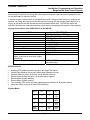
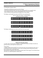
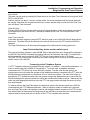
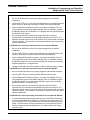
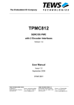
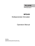
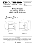
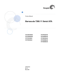
1
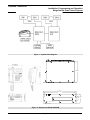
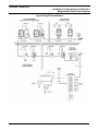
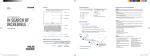
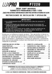
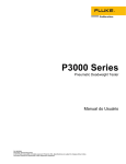
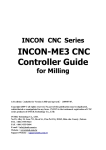
Industrial Communications Worldwide Merge/Isolate Zone Control System Model MIZCS Installation, Programming & Operation P006737 Rev. B 080730 7/28/2014 11:46 AM 7552 - 10th Street. N.E. Calgary Alberta, Canada T2E 8W1 Ph: 403.258.3100 \ email:[email protected] \ www.guardiantelecom.com Guardian Telecom Inc. Installation, Programming and Operation Merge/Isolate Zone Control System Table of Contents Package Contents .................................................................................2 Overview ...............................................................................................3 MICON Features ...................................................................................4 MICAB Back Panel Connector Tables.................................................10 Installing the Merge/Isolate Master Switch Unit (MICAB)....................13 Potentiometer Adjustments on the MICABs ........................................14 Ten Zone Merge/Isolate System Description ......................................14 Installing Multiple Merge/Isolate Controllers (MICONs).......................15 Programming of MICABs and MICONs ...............................................15 Operation.............................................................................................18 Setting and Cancelling Alarms ............................................................20 Lamp Test and Auxiliary device monitor switch report ........................21 Connecting to the Telephone System .................................................21 Engineering Specifications ..................................................................26 MICON Replacement Parts .................................................................27 Warranty ..............................................................................................28 Disclaimer............................................................................................28 Warning ...............................................................................................28 Service Telephone Number.................................................................28 Feedback.............................................................................................28 Guardian Product Return ....................................................................29 Page/Talk System Models and Options ..............................................30 Typical Page/Talk Installation..............................................................31 Table of Figures Figure 1 - System Block Diagram .........................................................6 Figure 2 - Dimensions MICON & MICAB ..............................................6 Figure 3 - MICON Features...................................................................7 Figure 4 - MICON Desk Top Mounting..................................................7 Figure 5 - MICON Wall Mounting ..........................................................7 Figure 6 - Back Panel Wiring Connections ...........................................8 Figure 7 - Front Panel Adjustments ......................................................8 Figure 8 - MICON PCB Layout..............................................................9 Figure 9 - MICAB Jumper Settings .......................................................9 Figure 10 - Examples of Auxiliary Alarm Inputs ..................................11 Figure 11 - Page/Talk System Wiring (typical application)..................12 Figure 12 - Page/Talk Wiring Connections (Typical Application) ........12 Package Contents (1) P9000 Merge/Isolate Control System Master Switch Unit (1 to 6) P9001 Merge/Isolate Control System Desk Sets (1) Installation & Operation Manual Page 2 Guardian Telecom Inc. Installation, Programming and Operation Merge/Isolate Zone Control System Overview Merge/Isolate System The function of the Merge /Isolate system is to merge and re-isolate up to five (or ten with expansion unit) zones of Guardian Page/Talk or GAI-Tronics Page/Party® system Stations and Amplifiers. The system is comprised of a Master Zone Control Unit (MICAB) and one to six Control Console Stations (MICONs). Each MICAB has a five zone page line mixer, which allows the master controller to simultaneously monitor merge requests through the page lines of all zones. The system can merge 2, 3, 4 or all 5 zones and is also able to merge another zone into a merged zone group later – for example zones 1 & 2 can be merged and zone 3 can subsequently be added. The isolate function can be performed separately as well – for example zone 2 can be re-isolated from zone 1 & 3 leaving them to converse alone. The system has controls to merge and isolate all five zones in one step, which is very useful in emergency situations. The system has the ability to be configured so that if an alarm occurs and the operator needs to send a page, the alarm will be muted while the MICON is in paging mode. When the Push To Page is released, the alarm tone returns to full volume. The MICON has the ability to trigger and reset up to 10 alarm channels from an alarm generator, such as Guardian’s AG17. It also displays two summary alarms in the form of LED indicators. The inputs for these are located on the MICAB and are a simple dry contact format. Some examples for use of the two alarms monitors are; the facility alarm activation, which could show that an alarm has been activated somewhere in the facility, either from the MICON or from an external switch. The other could be tied into a UPS or door switch or other sensor as considered essential to provide a visual monitoring aid. The MICAB has connections for a telephone interface which – with operator assistance – allows telephone calls to be made and received. The system has one set of Page & Talk merge bus lines – the common Page Line & one predetermined Talk Line. Separate merged zone groups is not achievable, only one group of merged zones at one time can be performed. The system can accommodate up to six MICONs working in parallel. It can also be expanded with another Five Zone MICAB working in tandem for merging and isolating up to ten Page/Talk zones. The MICAB can be configured by the factory for 120VAC, 230VAC or 24VDC operation. The MICONS are phantom powered by the MICAB eliminating the need for a local power supply for each MICON. The MICABs are rack mounted units with user access to zone conductor terminations (one pair of page & one pair of talk wires per zone), Alarm Control, and Telephone Interface terminations. Each MICON can be programmed for a unique level of control which can range from a low level monitor desk set with no control up to a full control unit. This offers the advantage of limiting what alarms or zones a station can set, clear or merge. Page 3 Guardian Telecom Inc. Installation, Programming and Operation Merge/Isolate Zone Control System MICON Features Construction Can be configured for Desktop or Wall mount Magnetic reed hook-switch (> 1,000,000 operations) Glass Filled Polyester Thermoset housing Integrated paging speaker Noise Canceling Microphone Removable Handset Latches for on hook retention Ergonomic handset with push to page button Heavy-duty industrial handset cord Heavy Duty Urethane Coated Water Tight Membrane Keypad 2 Line X 16 Character Back Lit LCD Display Hearing aid compatible receiver Extended length (up to 20ft) handset cord - Contact Guardian Sales for details Cable Entrances Includes 1 cable gland Support for two additional glands for external peripherals Mounting Simple field installation - desktop or wall mount Each MICON comes with 50M (164ft) of cable but will operate up to 500m (1,640ft). Options Extended length handset cord 6m (20ft) - Contact Guardian Sales for details Extended MICON cable – Contact Guardian Sales for details Page 4 Guardian Telecom Inc. Installation, Programming and Operation Merge/Isolate Zone Control System MICAB Features Construction Heavy duty Steel – Corrosion protected and powder coated. Standard 19” Rack Mount – 3U height Connectors Screw terminals accommodate up to 14 AWG cable Indicators and Controls Front Panel LED displays merged zones Front and back panel access to system audio controls and configuration. Support Five Zones, can be expanded to ten zones Up to 6 Master Control Stations Alarm tone generator Telephone interface module Alarms Remote Alarm Control and Monitor System Summary Alarm Support for Data Communications Monitoring Support for door alarm, loop power monitoring (Optional) Mounting Rack mount Options Rack door alarm switches, and loop power monitoring sensors Page 5 Guardian Telecom Inc. Installation, Programming and Operation Merge/Isolate Zone Control System Figure 1 - System Block Diagram 12.2" [310mm] 19.0" [483mm] 18.3" [465mm] Guardian Telecom Inc. 5.2" [132mm] 2.25" [57mm] MICAB-MERGE ISOLATE CABINET R0.125" [R3mm] Figure 2 - Dimensions MICON & MICAB Page 6 Guardian Telecom Inc. Installation, Programming and Operation Merge/Isolate Zone Control System Figure 3 - MICON Features Figure 4 - MICON Desk Top Mounting Figure 5 - MICON Wall Mounting Page 7 Guardian Telecom Inc. Installation, Programming and Operation Merge/Isolate Zone Control System MICON 1 MICON 2 MICON 3 ALARM LOGIC INPUT MICON 4 ALARM LOGIC OUTPUT A MICON 5 POWER ALARM LOGIC OUTPUT B FUSE 1.25A 120VAC + TALK PAGE PTTI TALK PAGE ZONE 1 LINE Z ADJUST TALK PAGE ZONE 2 LINE Z ADJUST TALK PAGE ZONE 3 LINE Z ADJUST TALK PAGE ZONE 4 LINE Z ADJUST TALK PAGE ZONE 5 LINE Z ADJUST - + - 1 2 AUX ALARM INPUTS TALK DATA MIX PWR PAGE MASTER/SLAVE Figure 6 - Back Panel Wiring Connections SEE DETAIL 1 F2 JP3 JP4 R 17 DETAIL 1 R 154 JP2 JP5 R17 R154 R60 Data Threshold Pot Mixed Line Level Pot. Merged Page Line Level Pot. MERGED ZONE INDICATOR LED Refer to Figure 9 for detailed jumper settings Figure 7 - Front Panel Adjustments Page 8 R 60 JP1 Guardian Telecom Inc. Installation, Programming and Operation Merge/Isolate Zone Control System HOOK SWITCH PTP (RED) PTP (GREEN) MIC + (BLACK) MIC - (WHITE) RX (YELLOW) RX (YELLOW) HANDSET LCD DISPLAY J5 J6 J7 MICON Connector Pin # Function 1 Merged Talk Line A 2 Merged Talk Line B 3 Merged Page Line A 4 Merged Page Line B 5 Data Signal A 6 Data Signal B 7 24VDC 8 VDC Ground 9 Mixed Signal A 10 Mixed Signal B Note: Cable has one spare pair of conductors RX VOLUME SIDE TONE CONTROL 1 J3 J4 J1 TX VOLUME 10 DATA THRESHOLD CONTROL 45 SPEAKER J2 MICON CABLE Figure 8 - MICON PCB Layout JP1 – Merged Talk Line Impedance Control Position Pins Description JP2 1, 2 PTTI Not Installed 2, 3 PTTI Installed or Slave MICAB Configuration JP 2, 3, 4 – Master / Slave Control Position Pins Description JP3 JP4 1, 2 2, 3 Master MICAB Select Second MICAB Slave Select JP5 – Merged Page Line Impedance Control Position Pins Description 1, 2 Master MICAB Select 2, 3 Slave MICAB Select Figure 9 - MICAB Jumper Settings Page 9 Guardian Telecom Inc. Installation, Programming and Operation Merge/Isolate Zone Control System MICAB Back Panel Connector Tables (pin numbering is from left to right) Power Input Connector Pin # Function 1 Neutral 2 Ground 3 Hot Aux. Alarm Input Connector Pin # Function 1 Warning 1 - Dry contact input 2 Ground 3 Warning 2 - Dry contact input 4 Ground Zone (1 - 5) Connectors (Zone 6 -10 in Slave MICAB) Pin # Function 1 Isolated Talk Line A 2 Isolated Talk Line B 3 Isolate Page Line A 4 Isolate Page Line A Master / Slave Connector Pin # Function 1 Merged Talk Line A 2 Merged Talk Line B 3 Merged Page Line A 4 Merged Page Line B 5 Data Signal A 6 Data Signal B 7 N/C 8 VDC Ground 9 Mixed Signal A 10 Mixed Signal B Pin # 1 2 3 4 Alarm Logic Input Connector (connected to AG17 Logic Outputs) Pin # Function 1 Alarm I/P #1 2 Alarm I/P #2 3 Alarm I/P #3 4 Alarm I/P #4 5 Alarm I/P #5 6 Alarm I/P #6 7 Alarm I/P #7 8 Alarm I/P #8 9 Alarm I/P #9 10 Alarm I/P #10 11 Alarm I/P Common 12 Alarm I/P Common PTTI Connector Function Merged Talk Line A Merged Talk Line B Merged Page Line A Merged Page Line B Alarm Logic Output Connector A (connected to AG17 Logic Inputs) Pin # Function 1 Alarm O/P #1 2 Alarm O/P #2 3 Alarm O/P #3 4 Alarm O/P #4 5 Alarm O/P #5 6 Alarm O/P #6 7 Alarm O/P #7 8 Alarm O/P #8 9 Alarm RST 1 10 Alarm Mute 11 Alarm O/P Common 12 Alarm O/P Common Alarm Logic Output Connector B (connected to AG17 Logic Inputs) Pin # Function 1 Alarm O/P #9 2 Alarm O/P #10 3 Alarm RST 2 4 Alarm Mute 5 Alarm O/P Common 6 Alarm O/P Common 7 Alarm Tone Input+ 8 Alarm Tone Input9 Alarm RST 1 10 Alarm Mute 11 Alarm O/P Common 12 Alarm O/P Common Page 10 Guardian Telecom Inc. Installation, Programming and Operation Merge/Isolate Zone Control System Note: The back panel MICON 1 - 5 connectors permit connection of five MICONs. If a sixth MICON is required, the cable of the sixth MICON may be connected to the MICON 5 connector, i.e. wired in parallel with #5. CASCADE CONFIGURATION See: MICAB Back Panel Connector Tables MICON #6 WIRED IN PARALLEL DRY CONTACT O/P AUX ALARM INPUT CONNECTOR If no dry contact use interface(simple interface shown) Figure 10 - Examples of Auxiliary Alarm Inputs Page 11 Guardian Telecom Inc. Installation, Programming and Operation Merge/Isolate Zone Control System Assignment System Power Ambient Noise Microphone Speaker Page Line Channel Group Muting of Loudspeakers Spare Conductor (Special Order) Designation Description J4A/J5A J4A/J5A J4A/J5A J6A J6A J7A J7A J2A/J3A J2A/J3A J2A/J3A J2A/J3A J2A/J3A J2A/J3A J2A/J3A J2A/J3A J2A/J3A J2A/J3A J2A/J3A J2A/J3A J2A/J3A J2A/J3A HOT COM GND MIC + MIC SPK + SPK PA Page Line PB " 1A Channel 1 1B " 2A Channel 2 2B " 3A Channel 3 3B " 4A Channel 4 4B " 5A Channel 5 5B " Mute Park n/a Extra Guardian System Cable Wire Jacket Color Black White Green n/a n/a n/a n/a Blue Red Red L. Brown Violet L. Brown Blue L. Brown Brown L. Brown Yellow L. Brown Guardian System Cable Wire - Stripe Color n/a n/a n/a n/a Red Blue Red Violet Blue Brown Yellow 14 AWG 14 AWG 14 AWG n/a n/a n/a n/a 18 AWG " 18 AWG " 18 AWG " 18 AWG " 18 AWG " 18 AWG " Orange 18 AWG Red 12 AWG Figure 11 - Page/Talk System Wiring (typical application) Figure 12 - Page/Talk Wiring Connections (Typical Application) Page 12 Wire Gauge Guardian Telecom Inc. Installation, Programming and Operation Merge/Isolate Zone Control System Installation of MICABs and MICONs Installing the Merge/Isolate Master Switch Unit (MICAB) WARNING – high voltages are present in this equipment when it is connected to the power source. Follow all appropriate electrical codes and use only approved electrical fittings for the installation. Install the MICAB in the rack. If the Control System is being installed in a five channel system determine which channel will be dedicated to the Merge/Isolate function. Ensure that none of the electrical connection circuits are live. Following the color codes in the System Wiring Connections table connect the Page Lines and the dedicated Talk Lines from each zone to the zone connectors on the back panel of the MICAB. Following the wire identification information in the MICAB to MICON Wiring Connections table connect the MICON(s) to the MICAB. Up to six MICONs can be connected to the MICAB. Connect the Alarm Generator. See: Figure 2 Dimensions MICON & MICAB See: Figure 11 Page/Talk System Wiring (typical application) See: MICAB Back Panel Connector Tables and Installing Multiple Merge/Isolate Controllers (MICONs) See: AG17 Manual To reduce noise on the Page/Talk system, 33 Ohm resistors – usually installed in a Line Balance Unit (LBU) – are connected across every page & talk line in every zone in/near the MICAB. The MICON provides the loading for all the page and dedicated merge talk lines. Resistors for the un-merged talk lines should be placed near the MICAB and remote LBU’s must not be connected. If a Telephone interface is to be connected into the system do so at this time. Jumpers JP1, JP2, JP3, JP4 and JP5 are configured at the factory for the most common setup. If changes to the system occur relocate jumpers to the appropriate positions. Ensure all connections are secure. Connect the power supply to J1. The voltage is set at the factory to 120 VAC, 230 VAC or 24 VDC. Ensure that the power being supplied is correct by checking the label on the back of the MICAB. Connect the MICAB power cord to the proper power source then turn on the power switch. Program the system. Adjust the front and back panel potentiometers. Test the system as described in the operation section. Page 13 See: LBU Manual See: PTTI Manual See: Figure 9 - MICAB Jumper Settings See: Programming of MICABs and MICONs See: Potentiometer Adjustments on the MICABs See: Operation Guardian Telecom Inc. Installation, Programming and Operation Merge/Isolate Zone Control System Potentiometer Adjustments on the MICABs Back Panel access Potentiometers The Page line impedance adjusting potentiometers for each of the isolated zones are located next to the Zone connectors on the back panels of both Master and Slave MICABs. With the Page Line not in use inject a test signal into the Page Line. Adjust the potentiometer in the Line Balance Assembly until the signal on the Page Line reads 0.5VRMS. If new stations are added to a zone, the Page Line impedance of that zone should be adjusted to adapt to the new load. Front Panel access Potentiometers The Merged Page line impedance adjusting potentiometer is located on the front of the Master MICAB once the Plexiglas is removed. This adjustment will affect the impedance of the merged page lines. Adjust it when the system is first set up or when stations are added to the system. The mixed line signal strength adjusting potentiometer is located at the front of the MICAB and is accessible once the Plexiglas is removed. All the audio signals on the isolated and merged page lines are mixed and sent back to the MICON speakers to monitor requests. A system may have one to six MICONs. This potentiometer is utilized to adjust the mixed line audio for the existing load (one to six MICONs). Adjust this potentiometer as follows: Using any MICON as a reference station set the speaker volume to a maximum level. Adjust the mixed line level potentiometer until the reference MICON picks up lowest noise. Page from one of the Page/Talk stations from an isolated zone. Listen to the speaker volume on the reference MICON (with speaker volume to max.). Adjust the mixed line level pot until the speaker on the reference MICON provides an acceptable audio level (~ 85dB @ 0.5 meter). Adding or removing MICONs in the system may affect the speaker volume of the other MICONs. If the volume control in the MICON cannot compensate for the increase or decrease of the speaker volume, the system may require re-adjustment of this potentiometer. The data line Signal Threshold potentiometer is located at the front of the MICAB and is accessible once the Plexiglas is removed. This adjustment affects the received data signal strength detection threshold of the MICAB. Adjust it until the MICAB can detect the instructions sent from the MICONs. See: Figure 6 - Back Panel Wiring Connections See: Figure 7 - Front Panel Adjustments Ten Zone Merge/Isolate System Description A Ten Zone Merge/Isolate System consists of two MICABs, and a maximum of six MICONs. Of the two MICABs, one is configured as the master, and the other one as the slave. All six MICONs have the same status in accessing the MICAB on a first come first served basis. The full capacity of the system is ten zones. If the setup is less than six zones, one MICAB is all that is required. The system supports an alarm tone generator, a telephone interface module and line balance assemblies (omit). The system has to be set up prior to operation. Page 14 Guardian Telecom Inc. Installation, Programming and Operation Merge/Isolate Zone Control System Installing Multiple Merge/Isolate Controllers (MICONs) Up to six controllers (MICONs) can be connected to the MICABs. MICON wiring can be in parallel, series, or a combination of both. MICONs can be desk mounted or wall mounted If a MICON is to be desk mounted simply set it in position. If a MICON is to be wall mounted remove the faceplate and secure the base to the wall in the desired location, with the deepest dimension towards the bottom. The handset retainer clips should be installed to the handset cradle to hold the handset properly. Wire the MICONs back to the MICAB. Ensure all connections are secure. Program the MICON and the MICAB. Test the system by merging zones as would be done during normal operations. Tip: There are only five connections for MICONs on the MICAB. The sixth MICON can be wired in parallel with #5. Caution: The electronic components are secured to the faceplate, handle with care. See: MICAB Back Panel Connector Tables See: Programming of MICABs and MICONs Programming of MICABs and MICONs MICON Programming: Once the system is powered up the MICON is ready for programming its function registers. To enter Programming Mode, press the [PVT] key and the [LMP TST] key simultaneously. The LCD display will respond with a greeting message and then the main menu. 1 = MICON, 2 = MICAB 3 = AlrZn, 4 = STORE 1. MICON setup: Press key [1] while in the main menu to program the existing MICON. Once key [1] is selected the screen will display the register number and its setting. Enter or change the setting by keying in the proper numeric key. Any out of range entry will be prompted with a message. Use the [VOL UP] or the [VOL DWN] to scroll through all the other registers. Once all these registers are verified to be correct, press the [PVT] to get back to the main program menu. The following table describes the MICON registers and functions: Register code Reg00 Function Station Number Reg01 Alarm key lockout Reg02 Reg03 Language Speaker Volume Reg04 Zone key lockout Reg05 Select default Description The MICON station number Note 1 Alarm key access Note 2 English Note 3 Power up Speaker volume Note 4 Zone key access Note 5 Restoring the MICON to the default settings Note 6 Page 15 Parameter 1 digit number (1 to 6 and 8) 8 = station disabled 0 = disable access 1 = access English only 0 to 7 Default Settings 8 0 = disable access 1 = access 0, or 7 to restore default settings 1 1 1 3 1 Guardian Telecom Inc. Installation, Programming and Operation Merge/Isolate Zone Control System Notes: 1) All MICON stations have to be programmed with a station number. The station numbers range from 1 to 6. Only station number 1 can get access to program the other functions of the MICAB. There cannot be two stations with the same station number. Stations have a default setting of 8 to ensure that adding a new station does not conflict with existing stations. The default setting must be changed to a number between 1 and 6 that has not been assigned to another station. 2) Once Reg01 is stored with 0, all the red alarm function keys will be disabled. Pressing these keys will result in receiving the deny message on the display. 3) Only English is supported in this version. 4) Use volume keys on the keypad to alter the initial volume. 5) Once Reg04 is stored with 0, all the blue zone function keys (excluding the [PVT] key) will be disabled. Pressing of these keys will result in receiving the deny message on the display. 6) Setting Reg05 to 0 or 7 will restore all the registers back to the default settings of the MICON. MICAB programming: Programming the MICAB is done in two stages. First, use the MICON (station 1) to register all the settings that are available in the MICAB. Once the system registers are verified as correct, transfer these registers from the MICON to the MICAB. Below is the main menu on the MICON: 1 = MICON, 2 = MICAB 3 = AlrZn, 4 = STORE 2. MICAB setup: Press key [2] while in the main menu to program the MICAB function registers. Once key [2] is selected the screen will display the MICAB register number and the setting. Enter or change the setting by keying in the proper numeric key. Any out of range entry will be prompted with a message. Use the [VOL UP] or the [VOL DWN] to scroll through all the other registers. Page 16 Guardian Telecom Inc. Installation, Programming and Operation Merge/Isolate Zone Control System The following table describes the MICAB registers and functions: Register code Reg06 Reg07 Function Master MICAB MICON station #1 Reg08 MICON station #2 Reg09 MICON station #3 Reg10 MICON station #4 Reg11 MICON station #5 Reg12 MICON station #6 Reg13 Slave MICAB Reg14 Reg15 Merged Time Default Settings Description Always exists Assertion of its existence in the system (Note 1) Assertion of its existence in the system (Note 1) Assertion of its existence in the system (Note 1) Assertion of its existence in the system (Note 1)) Assertion of its existence in the system (Note 1) Assertion of its existence in the system (Note 1) Assertion of its existence in the system (Note 1) (Note 2) Restoring the MICON to the default settings (Note 3) Parameter 1 = exists 0 = not installed 1 = installed Default Settings 1 1 0 = not installed 1 = installed 0 0 = not installed 1 = installed 0 0 = not installed 1 = installed 0 0 = not installed 1 = installed 0 0 = not installed 1 = installed 0 0 = not installed 1 = installed 0 1-9 X 10 minutes 0, or 7 to restore default settings 6 1 Notes: 1) All MICON stations and the MICAB slave units have to be programmed to indicate their existence in the system. Any MICON station or MICAB slave that is not registered will not be polled by the MICAB master unit. 2) The merged time is the maximum duration of zone merging since the last change. Once the time runs out the merged zones will be isolated. 3) Setting Register 15 to 0 or 7 will restore all the registers back to the default settings in the MICAB. 3. Alarm Channel and the Associated Merged Zones setup: Press key [3] while in the main menu to program the MICAB Alarm function registers. Once key [3] is selected the screen will display the MICAB Alarm register number and the setting. Enter or change the zone that will be merged when the existing Alarm channel is activated. Use the [VOL UP] or the [VOL DWN] to scroll through all the other registers. Page 17 Guardian Telecom Inc. Installation, Programming and Operation Merge/Isolate Zone Control System The following table describes the MICAB Alarm registers and functions: Alarm Register Associated Zones Description Parameter Zone 1 to 10 Alarm 01 1234567890 Alarm channel 1 and its associated zones Alarm 02 1234567890 Alarm channel 2 Zone 1 to 10 and its associated zones Alarm 03 1234567890 Alarm channel 3 Zone 1 to 10 and its associated zones Alarm 04 1234567890 Alarm channel 4 Zone 1 to 10 and its associated zones Zone 1 to 10 Alarm 05 1234567890 Alarm channel 5 and its associated zones Alarm 06 1234567890 Alarm channel 6 Zone 1 to 10 and its associated zones Alarm 07 1234567890 Alarm channel 7 Zone 1 to 10 and its associated zones Alarm 08 1234567890 Alarm channel 8 Zone 1 to 10 and its associated zones Zone 1 to 10 Alarm 09 1234567890 Alarm channel 9 and its associated zones Zone 1 to 10 Alarm 00 1234567890 Alarm channel 0 and its associated zones Default Settings All Zones All Zones All Zones All Zones All Zones All Zones All Zones All Zones All Zones All Zones 4. Transfer the registers settings in the MICON to the MICAB: Pressing key [4] while in the main menu will cause the MICON to send all the register settings to the MICAB. If the master MICAB and the slave MICAB exist they both will be updated with the new settings. If the transfer is successful the MICAB will blink all the zone lights. Operation Requesting a Merge: The caller first sets the Talk Channel Selector to the dedicated Talk channel. A request for a merge is made by the caller making a Page to the Control System operator in the normal manner. The system circuitry has a five zone mixer therefore a Page from any zone will be heard by the operator. If the requirement is for a simple Merge the information can be conveyed in the original Page. If the requirement is more complicated – say an inquiry as to the Zone in which a particular individual is located – the Page can simply ask the operator to speak on the dedicated line. In this case the operator can check on the LCD display for the origin of the page zone; then press the button to merge the Zone from which the call is coming, and can then have a conversation with the caller. The operator can page the person being called and the person requesting the merge will know that the merge has been made when the called party comes on the line. Page 18 Guardian Telecom Inc. Installation, Programming and Operation Merge/Isolate Zone Control System Alternatively the operator can merge the zones requested and the caller can make the page and wait for the called party to come on the line. If a merge request comes in from an unmerged zone while a merge of other zones is in progress the operator can merge the zone from which the request is coming with the merged zones and butt in, to convey to the person that the request cannot be processed at that time. The MICON display will indicate if the caller has a handset picked up in their zone by illuminating the respective zone number. Keying of instructions from a MICON Unit to the MICAB: ACTION KEY STROKES MERGE, (ZONE(s)), MERGE ISOLATE, (ZONE(s)), ISOLATE MERGE, ALL ISOLATE, ALL ALARM SET, (alarm #) ALARM RESET ALARM CLEAR LAMP TEST VOLUME UP VOLUME DOWN PVT Merge zones Isolate zones Merge all zones Isolate all zones Trigger alarm Reset alarm (from highest priority first) Clear all alarms Test alarm LEDs Increase speaker/receiver volume Decrease speaker/receiver volume Cancel incomplete instructions (Merge zones, Isolate zones, and Alarm trigger instructions) Enter into Programming mode PVT + LMP TST (pressing both keys simultaneously) MICON Controls Standard PTP handset operation similar to any Page/Talk station. Internal Page Speaker volume up & down (when handset on hook) Handset Receiver volume up & down (when handset off hook) Remote Alarm System activation (10 possible alarm triggers) Remote Alarm System resetting Remote Alarm System clearing Two summary LEDs on the unit face (indicating alarm activation & M/I system status) Lamp test button (to check all Alarm LED indicators) Keypad Matrix MRG ISO PVT ALL 1 2 3 LMP TST 4 5 6 ALM SET 7 8 9 ALM CLR VOL DWN 0 VOL UP ALM RST Page 19 Guardian Telecom Inc. Installation, Programming and Operation Merge/Isolate Zone Control System LCD Indication of System Status: • Merged Zones (Displayed at same time as Active Zones) • Active Zones (showing a station is off hook on pre-determined Talk Line in respective zone) • Alarm Setting (as a priority override to normal Merged /Active Zones status display) • Alarm Activation (showing alternately with Merged /Active Zones display) The Display is as illustrated below when the MICON is in the activating state: M A Note: The right arrow symbol (>) indicates that the command has not been completed R G - > : 1 . . . . . . . . C T V : 1 . . . . . . . . 0 0 I A S C O T V A A L C A T R M V > : : . . . . . . . . . . . . . . . . . . . . : S 1 E T . . : . . 2 . . . . 0 The Display is as illustrated below when the MICON is in the report state: M A R C G T 1 1 . . . . . V : : I A S C O T M A R L . . . . . . . . . . . 0 0 V : : . . . . . . . . . . . . . . . . . . . . G A R M : : 1 1 . 2 . . . . . . . 3 4 5 6 7 8 9 0 0 Setting and Cancelling Alarms If an AG17 Alarm Tone Generator or similar is connected into the system the Master Controller can generate alarms on the Page lines of selected zones. Trigger Alarms: To trigger an alarm press [ALM SET] key, then select the alarm channel through the numeric keys. If another [ALM SET] key is pressed prior to any numeric key being entered, the MICON will exit the alarm setup and return to the standby state. Once the alarm is triggered the zones associated with the alarm will be merged. The red General Alarm LED will be on to alert the operator for alarm status. Page 20 Guardian Telecom Inc. Installation, Programming and Operation Merge/Isolate Zone Control System Alarm Reset: The alarm can be reset by pressing the Reset switch on the Alarm Tone Generator or through the [ALM RST] on the MICON. After the reset of one alarm, if there is a queue alarm, the zones associated with the queue alarm will be merged. Otherwise the merged zones will have a seven second delay to receive the All Clear Tone from the Alarm Tone Generator. Alarm All Clear: Pressing [ALM CLR] key will clear all the previously triggered alarms. Once all the alarms are cleared, the merged zones will still be held for 7 seconds to receive the All Clear Tone from the Alarm Tone Generator. Alarm Tone Override: If the alarm has been triggered, using the PTP switch to page on one of the MICONs will attenuate the alarm tone. The alarm tone will be restored to the normal volume once the PTP switch on MICON is released. The Page/Talk stations on all the zones while paging will not attenuate the existing alarm tone. Lamp Test and Auxiliary device monitor switch report There are two monitor switches in each MICAB. Each of these switches once closed will be reported to the MICON. The MICON will display the warning status on the Summary Alarm LED. To check which switch caused the warning press the [LMP TST] to have a report shown on the LCD display. The [LMP TST] key is also used to check the two Alarm warning LEDs for failure, as well as reading the station number of the MICON. Connecting to the Telephone System If a PTTI Telephone Interface is integrated into the system, it is possible – with operator assistance – to make or receive calls from a PABX or Central Office. To receive calls, a telephone extension connected to the PTTI phone line near a MICON is required. To make a call into the system, the outside caller must first contact the operator at the telephone extension connected to the PTTI near the MICON and ask to be patched in to whichever zone or zones are required. The caller then hangs up and dials the PTTI extension number after the operator merges the appropriate zone or zones with the MICON and pages the person or persons to whom the outside caller wishes to speak. Alternatively the caller can press appropriate dial keys to put the PTTI into paging mode and page the person to whom they wish to speak. To make a call from the Page/Talk system to a telephone system, the operator must have a MICON connected near the PTTI telephone extension. When a request to make an outside call is received from the Page/Talk system, the operator must first call the desired phone number on the PTTI line and then when contact is made press the Merge keys on the MICON to connect the zone in which the call request came from and press the Link button on the PTTI to complete the connection. Page 21 Guardian Telecom Inc. Installation, Programming and Operation Merge/Isolate Zone Control System Field Repairs & Adjustments Field repairs may only be carried out by qualified technicians using OEM parts. Substitution of parts voids warranty and may pose a hazard to users of the equipment. Disconnect power to the MICAB before attempting repairs. Perform the necessary repairs or adjustments. See: MICON Replacement Parts MICAB Fuse Replacements The Main power supply fuse is in the back panel fuse holder. The +24VDC power supply fuse is accessible through the front of MICAB with the Plexiglas cover removed. Remove the old fuse and insert the new fuse. WARNING! Replace only with the correct fuse as described in the Engineering Specifications section. Failure to do so will void the warranty. If, on reconnecting power, the fuse fails, remove all MICONs connectors from the MICAB. Check the power supply source and the rating on the MICABs. Apply power to the MICAB again if power source is correct. If the MICAB is OK, check the MICON cables for short between power pin and ground pin. Replace cable if required. Connect the MICONs back to the MICAB one at a time to identify the problem MICON. Programming Difficulties The MICAB cannot be programmed. Be sure all the jumpers on the Master MICAB are set up as the Master MICAB. If there is only one MICAB in a system the jumper must be set as the Master MICAB. If there are two MICABs in a system, one must be set up as the master and the other as slave. Two MICABs cannot both be the Master MICAB or the Slave MICAB. Remove all other MICONs except the one that is used for programming the MICAB. Use the [LMP TST] key to verify that the MICON is set as station number 1 (the master MICON). Press the [PVT] key and the [LMP TST] key simultaneously to get into the Programming Mode. Change the MICON station number to 1. Program other settings of the MICAB, and store the settings by uploading the settings from the MICON to the MICABs. If the uploading is done successfully the Zone LEDS on the MICABs will flash once. Plug all other MICON connectors back to the MICABs. All MICONs must be programmed with different station numbers. Page 22 See: Figure 6 - Back Panel Wiring Connections, Figure 7 - Front Panel Adjustments and Engineering Specifications Guardian Telecom Inc. Installation, Programming and Operation Merge/Isolate Zone Control System The MICAB does not accept instructions from all MICONs. Be sure all the MICON connectors are properly plugged into the MICAB receptacles. Use the[LMP TST] key to verify that all the MICONs are set up without identical station numbers. Write down the station numbers of all problem MICONs. Use the Master MICON (station number 1) to program the MICAB. From the main programming menu of the Master MICON, select 2 = MICAB to program the MICAB settings. Be sure Register # 7 to Register #12 are registered with all the MICONs in the system. Enter a Merge instruction from a MICON. Adjust the Data Threshold Potentiometer in the MICAB until the MICAB recognizes the instruction. The adjustment should start from the center position of the potentiometer and adjust counter-clockwise. If the operation is unsuccessful restart the procedure with a clockwise adjustment. The MICAB does not accept instructions from two particular MICONs. Be sure all the MICON connectors are properly plugged into the MICAB receptacles. Use the [LMP TST] key to verify that the MICONs do not have identical station numbers. Write down the station numbers of all problem MICONs. Use the Master MICON (station number 1) to program the MICAB. From the main programming menu of the Master MICON, select 2 = MICAB to program the MICAB settings. Be sure the problem MICONs are registered in the proper Registers (Register # 7 to Register #12). Change the MICONs with identical station number to different station numbers. The MICAB does not accept instructions from one particular MICON. Be sure the MICON connector is properly plugged into the MICAB receptacle. Use the [LMP TST] key to read the problem MICON station number. Use the Master MICON (station number 1) to program the MICAB. From the main programming menu of the Master MICON, select 2 = MICAB to program the MICAB settings. Be sure the problem MICON is registered in the proper Register (Register # 7 to Register #12). Enter a Merge instruction from a MICON. Adjust the Data Threshold Potentiometer in the MICAB until the MICAB recognizes the instruction. The adjustment should start from the center position of the potentiometer and adjust counter-clockwise. If the operation is unsuccessful restart the procedure with a clockwise adjustment. The MICAB does not accept zoning instructions from one particular MICON. The particular MICON may be programmed to ignore the MRG and ISO keys. Convert the MICON back to recognize the zoning keys by pressing the [PVT] key and the [LMP TST] key simultaneously to get into the programming mode. Select 1= MICON from the main programming menu to program the MICON settings. Change the MICON Register #4 to 1 in order to enable the Zoning instruction keys. Page 23 Guardian Telecom Inc. Installation, Programming and Operation Merge/Isolate Zone Control System The MICAB does not accept Alarm instructions from one particular MICON. The MICON may be programmed to block the ALR SET, ALR CLR and ALR RST keys. Convert the MICON back to recognize the Alarm instruction keys by pressing the [PVT] key and the [LMP TST] key simultaneously to get into the programming mode. Select 1= MICON from the main programming menu to program the MICON settings. Change the MICON Register #1 to 1 in order to enable the Alarm activating instruction keys. The Slave MICAB does not accept instructions from the MICONs. Be sure the Master/Slave cable connectors are proper plugged into both MICAB receptacles. Be sure all the jumpers in the Master and the Slave MICABs are properly set. Set the Data Threshold Potentiometer in the Slave MICAB to the same setting as the one in the Master MICAB. Set MICON station number 1 to programming mode. Select 2 = MICAB from the main programming menu to program the MICAB settings. Change Register #13 to 1 in order to register the Slave MICAB to the Master MICAB. From the main menu select 4 = STORE to upload the settings from the MICON to the MICABs. If the uploading is done successfully the Zone LEDS on the MICABs will flash once. Electrical Hardware Problems No LCD display on MICON Check the ZONE connectors on the back panel of the MICABs for loose wiring. Check MICON cable wiring for loose wiring. MICONs receive busy Dedicated Talk line in a particular zone all the time. Be sure no resistor is connected across the Dedicated Talk line. Be sure all stations in that zone are on hook. Check for short between Dedicated Talk line conductors. Telephone Interface Module does not release phone line when all zones are isolated. Be sure the JP1 jumpers on both Master and Slave MICABs are in position 2 and 3. MICON cannot trigger or reset the Alarm Tone Generator. Check the ALARM LOGIC OUTPUT-A connector and ALARM LOGIC OUTPUT-B connector for loose wiring. No Alarm tone in the merged page line when the AG17 is triggered. Be sure the AG17 is in the Pulse Triggering Mode. Check ALARM LOGIC OUTPUT B connector to AG17 for loose wiring on audio output connector. Adjust the audio output control potentiometer on the AG17 to the proper Page Line level. Page 24 Guardian Telecom Inc. Installation, Programming and Operation Merge/Isolate Zone Control System MICON displays incorrect Alarm Tone triggering channel. Check ALARM LOGIC INPUT connector for correct wiring to AG17. High/Low volume on all speakers in a zone With the Page/Talk Station volume controls within a zone set to a typical level, adjust the Zone Page Line potentiometer on the back panel of the MICABs for the proper page speaker volume. Noisy Page or Talk lines Be sure all wiring to the Page and Talk line terminal connectors on the back panel are properly fastened to the screw terminal connectors. Check the problem audio line by pulling the conductor on the connector to be sure that the electric wire is securely fastened to the connector and not just loosely inserted. Low volume on all speakers on the Merged Page Line Be sure the JP5 jumper on the Master MICAB is in position 1 and 2. Be sure the JP5 jumper on the Slave MICAB is in position 2 and 3. With the Page/Talk Station volume control set to a typical level, adjust the Merged Page Line potentiometer in the Master MICAB for the proper page speaker volume. High volume on all speakers on the Merged Page Line With the Page/Talk Station volume control set to a typical level adjust the Merged Page Line potentiometer in the Master MICAB for the proper page speaker volume. Cross Talk on the Page and Talk Lines in a zone Check the ZONE connectors on the back panel of the MICABs for cross wiring between the Talk and Page pairs. Cross Talk on the Page and Talk Lines while merged Be sure the proper cable is used for MICON stations. Check the PTTI connector on the back panel of the MICAB for cross wiring. Check the Master/Slave connectors on both the Master and Slave MICABs for cross wiring between the Talk and Page pairs. Check all the MICON cable connectors for cross wiring between the Talk and Page pairs. High/Low volume on all speakers in the MICONs Set all MICON speaker volume to midrange. Page from a MICON and adjust the MIXED LINE LEVEL potentiometer on the front of the MICABs until the MICONs receive the proper speaker volume. Page 25 Guardian Telecom Inc. Installation, Programming and Operation Merge/Isolate Zone Control System Engineering Specifications ELECTRICAL REQUIREMENTS MICAB INPUT VOLTAGE AC INPUT FREQUENCY INPUT VOLTAGE/CURRENT/FUSE DC POWER SUPPLY FUSE 20 - 26 / 100-120 / 215-240 VAC, 24 - 30VDC 50/60HZ 24VDC/2.4AMP/2.5A , 3AG FAST BLOW 120VAC/1.2AMP/1.25A, 3AG FAST BLOW 240VAC/0.6AMP/0.75A, 3AG FAST BLOW 24VDC/2.4AMP/2.5A, 2AG FAST BLOW MICON INPUT VOLTAGE INPUT CURRENT AUDIO FREQUENCY RESPONSE PAGING SPEAKER VOLUME 24VDC 60mA RESETTABLE 300 3400 HZ ~85dB @ 0.5m ENVIRONMENTAL MICAB DUST & WEATHER TIGHT TEMPERATURE -10˚ to +60˚C (14˚ to +140˚ F) HUMIDITY 0 - 95% RH Non-Condensing CORROSION & DUST RESISTANT MICON TEMPERATURE -10˚ to +60˚C (14˚ to +140˚ F) HUMIDITY 0 - 95% RH Non-Condensing CORROSION & DUST RESISTANT Full Gasket Faceplate & Keypad MECHANICAL MICAB CONSTRUCTION DIMENSIONS (H X W X D) NET WEIGHT MOUNTING 16 GAUGE STEEL, ZINC DICHROMATE PLATED AND POWDER COATED 132 X 483 X 310 MM (5.2 X 19.0 X 12.2 INCHES) 8.2 KG/18 LBS RACK MOUNT Page 26 Guardian Telecom Inc. Installation, Programming and Operation Merge/Isolate Zone Control System MICON HOUSING MATERIAL DIMENSIONS (H X W X D) NET WEIGHT MOUNTING TEMPERATURE GLASS FILLED POLYESTER (CARBON LOADED) 144 X 238 X 282 MM (5.7 X 9.4 X 11.1 INCHES) 5.9 KG/8.6 LBS DESK OR WALL MOUNT -10 to +60˚C (17˚ to +140˚F) HUMIDITY 0 - 95% RH Non-Condensing CORROSION & DUST RESISTANT MICON Replacement Parts Part No. P9003 P002254 P006614 P006691 P006752 P006782 Description Handset Assembly Single Reed Switch Lock – Handset Retainer Bumper – ½” Diameter Urethane Liquid Crystal Display – 2 x 16 Characters PCBA – Merge Isolate Console Page 27 Guardian Telecom Inc. Installation, Programming and Operation Merge/Isolate Zone Control System Warranty Guardian Telecom warrants your product to be free of defects in material and workmanship for a period of one year. Guardian Telecom will repair or replace any defective unit that is under warranty free of charge. This warranty is null and void if any non-authorized modifications have been made to this product, or if it has been subjected to misuse, neglect, or accident. This warranty covers bench repairs only; such repairs must be made at Guardian Telecom or an authorized service depot. Guardian Telecom is not responsible for costs incurred for on-site service calls, freight, or brokerage. A return authorization must be obtained prior to warranty claims or repairs. Disclaimer The products covered by this manual are designed for use in Industrial Environments and/or Hazardous Locations. Due to the range of possible applications for these instruments the manufacturer will not be responsible for damages or losses of any kind suffered as a result of the use of this product, including consequential damages. Warning High voltages may be present in this product, ensure that power is removed before installing, performing maintenance or making repairs. Service Telephone Number 1-800-363-8010 Toll Free in North America Guardian Telecom provides a customer service telephone number which is toll-free within North America. If you need assistance when installing or operating this product, please call the toll-free telephone number between regular business hours (7:30AM-5:00PM), Mountain Standard Time. If you are calling outside of regular business hours, please leave a detailed message, and a member of Guardian Telecom’s Service Department will return your call as soon as possible. If your product requires service, Guardian personnel will supply you with an RMA (return materials authorization) number over the telephone or through our web site product return page. This number must be included with your return address and the name of the person to contact. Guardian Telecom Inc. 7552 - 10th Street N.E. Calgary, Alberta, Canada T2E 8W1 Toll-free 1-800-363-8010 Ph. (403) 258-3100 Fax. (403) 253-4967 www.guardiantelecom.com Feedback Guardian Telecom continually strives to make reliable, durable, and easy to use products. If you, as an installer or user of our equipment, have any suggestions for improvements to this or any of our products or documents, including this manual, we would appreciate hearing from you. Page 28 Guardian Telecom Inc. Installation, Programming and Operation Merge/Isolate Zone Control System Guardian Product Return Guardian products have been quality tested and are in full working order when shipped from the factory, given the rugged nature of these products shipping is not expected to damage a unit. In the unlikely event of a malfunction, Guardian follows the three step procedure below. Step I - On-Site Correction The most common source of difficulties with a new product is improper installation in one of two ways: incorrect wiring connections or connection to an incorrect power source. Product wiring needs to be properly connected to the on-site wiring. Correct wiring instructions are shown in the user manual included with the product. Step II - Return Materials Authorization (RMA) When a product has been installed following user manual instructions, and the unit fails to operate, the user must contact Guardian Telecom to obtain authorization to return the product. This can be done by completing a RMA form online at www.guardiantelecom.com, or by calling the service telephone number given in this manual. After providing information on the product, the owner and the nature of the problem, Guardian will issue a RMA number, to be shown on documentation returned with the product. In addition to the RMA number, shipping documents should include name, address and telephone number of the owner along with contact information for the person responsible for the repair and/or the user who identified the malfunction. (Where a product is being returned for repair from outside of Canada, customs documentation must show the product’s serial number, date of export [date of purchase], and a notation that the equipment is: “Canadian goods returning.”) Step III - Factory Authorized Service Once received, each product is carefully inspected and tested. If the product is under warranty, repairs are completed and the product returned to the owner, generally within five working days of receipt by the factory. A product that has been subjected to misuse, neglect or accident or is beyond the warranty period will be evaluated. The service department will provide the owner’s representative with a repair cost estimate. Once approved, repairs are completed and the product returned, generally within five working days. Page 29 Guardian Telecom Inc. Installation, Programming and Operation Merge/Isolate Zone Control System Page/Talk System Models and Options Indoor Handset Stations PTI-1 & PTI-5 P5550 P5551 P5552 P5553 P5554 P5555 P5556 P5557 Ambient noise sensor, single line Ambient noise sensor, five line Ambient noise sensor, headset connector, single line Ambient noise sensor, headset connector, five line Single line Five line Headset connector, single line Headset connector, five line Outdoor Handset Stations PTO-1 & PTO-5 P5560 P5561 P5562 P5563 P5564 P5565 P5566 P5567 Ambient noise sensor, single line Ambient noise sensor, five line Ambient noise sensor, headset connector single line Ambient noise sensor, headset connector five line Single line Five line Headset connector, single line Headset connector, five line Handset Explosion Proof Stations EXP-1 & EXP-5 P5930 P5935 Acoustic Booths P9010 P9035 P9029 Cable P006183 P006184 P006217 P006216 P005863 P005916 P005366 P005219 P006218 P7247 Indoor Speaker Amplifier Stations PSA-I GB406 Ambient noise sensor Speaker amplifier 2 Conductor 18AWG Industrial Armored Speaker Cable 2 Conductor 18AWG Industrial Standard Speaker Cable 4 Conductor 18AWG Industrial Armored Speaker Cable 4 Conductor 18AWG Industrial Standard Speaker Cable Heavy Duty 8 Conductor Armored Cable (Single Line Page/Talk) Standard Duty 8 Conductor Cable (Single Line Page/Talk) Heavy Duty 16 Conductor Armored Cable (Multi Line Page/Talk) Standard Duty 16 Conductor Cable (Multi Line Page/Talk) Heavy Duty 17 Conductor Armored Cable (Multi Line Page/Talk) Loudspeakers Ambient noise sensor, single line Ambient noise sensor, five line P5570 P5571 AB100 Aluminum or Steel full size AB1000 Glass Reinforced Plastic hood AB2000 Glass Reinforced Plastic full size GCW4T GBL650 Outdoor Speaker Amplifier Stations PSA-O P5572 P5573 Ambient noise sensor Speaker amplifier GB640 GCAR6 Desk Set Amplifiers PDA P5580 P5581 Ambient noise sensor Speaker amplifier GHP15 GHS15 Desk Set Stations (Complete) PTD & PDA P5590 P5592 P5593 Ambient noise sensor, amplifier and single line desk set Ambient noise sensor, amplifier and five line desk set Amplifier and single line desk set Amplifier and five line desk set P5940 Telephone Interface PTI P5591 GHS15IIN GHP20S GBA56EExeN GCAPEEX6 GHS15EExmN P5980 Line Balance Assembly LBU Alarm Tone Generator AG-17 P5960 P5970 GHS15ExdFM AM15XD2 With Relay Without Relay Page 30 SR40 Explosion Proof (Class I, Div. 1) Metal Horn Speaker 8 Watt Indoor Plastic Wall Speaker 8 Watt Indoor Cabinet Speaker 15 Watt Indoor Plastic Ceiling Speaker 20 Watt Indoor Metal Ceiling Speaker 10 Watt Metal Surface Mount Speaker 15 Watt Outdoor Plastic Horn Speaker 15 Watt Outdoor Metal Horn Speaker 15 Watt Hazardous Area (Zone 2) Metal Horn Speaker 20 Watt Hazardous Area (Zone 2) Plastic Horn Speaker 6 Watt Hazardous Area (Zone 1) Indoor Metal Ceiling Speaker 6 Watt Hazardous Area (Zone 1) Metal Surface Mount Speaker 15 Watt Hazardous Area (Zone 1) Metal Horn Speaker 15 Watt Hazardous Area (Class I, Div. 1) Metal Horn Speaker 15 Watt Hazardous Area Speaker (Class I, Div. 2) Metal Horn Speaker Guardian Telecom Inc. Installation, Programming and Operation Merge/Isolate Zone Control System Typical Page/Talk Installation Page 31 Guardian Telecom Inc. 7552 - 10th Street N.E. Calgary, Alberta, Canada T2E 8W1 Toll-free 1-800-363-8010 Ph. (403) 258-3100 Fax. (403) 253-4967 www.guardiantelecom.com E-mail: [email protected] (Click to open message box) Industrial Communications Worldwide © Guardian Telecom Inc. 2008