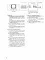
1
Owner's Manual
VIDEO / HI-FI SYSTEM EXPANDER
222 HARTREY AVENUE EVANSTON, ILLINOIS 60202-3696 U.S.A TELEPHONE (312) 866-2200 CABLE SHUREMICRO
NOTICE
This equipment generates and uses radio fre.
quency energy and if not installed and
1
properly, that is, i n strict accordance w i
manufacturer's instructions, may cause interlerence t o radio and television reception. I t has
The AVC20 offers the choice of three different types
of surround-sound effects: Dolby Surround, Spatial
Surround, or Concert Surround.
The AVC20 is equipped with Four Power amplifiers.
The AVC20 allows central control of most video equipment.
4 types of easy to operate volume balance controls.
The AVC20 is equipped with a sound memory circuit.
The Surround Indicator can be switched on or off.
The AVC20 can be used as a high output stereo amplifier when in the Balanced Transformerless (BTL) mode.
been type tested and found t o comply \n
'je
limits for Class €4 computing device i n
jr.
dance with the specifications i n Subpart J of
Part 15 of FCC Rules, which are designed to
provide reasonable protection against such
interference in a residential installation. However, there is no guarantee that interference
will not occur i n a particular installation. If this
equipment does cause interference t o radio or
television reception, which can be determined
b y turning the equipment o f f and on, the user
is encouraged t o try t o correct the interference
b y one or more of the following measures
-
TABLE OF CONTENTS
receiver
Special features . . . . . . . . . . . . . . . . . . . . . . . . . . . . . . . . . . . . . . . . . .
2
Surround-soundeffects . . . . . . . . . . . . . . . . . . . . . . . . . . . . . . . . . . . . . 3
Installing the glass door . . . . . . . . . . . . . . . . . . . . . . . . . . . . . . . . . . . . . 3
Locating speakers . . . . . . . . . . . . . . . . . . . . . . . . . . . . . . . . . . . . . . . . .
4
Connection of speakers . . . . . . . . . . . . . . . . . . . . . . . . . . . . . . . . . . . . . 5
Function names and operations - Front panel . . . . . . . . . . . . . . . . . . . . . . 6
Function names and operations - Rear panel. . . . . . . . . . . . . . . . . . . . . . . 8
Volume - Balance control . . . . . . . . . . . . . . . . . . . . . . . . . . . . . . . . ; . . 10
Use of wireless remote control . . . . . . . . . . . . . . . . . . . . . . . . . . . . . . . . 11
Use of the image enhancer switch . . . . . . . . . . . . . . . . . . . . . . . . . . . . . . 14
Applications . . . . . . . . . . . . . . . . . . . . . . . . . . . . . . . . . . . . . . . . . . . . 15
Example of use with a variety of different equipment
(Monophonic video deck) . . . . . . . . . . . . . . . . . . . . . . . . . . . . . . . . . . 20
(STEREO video deck) . . . . . . . . . . . . . . . . . . . . . . . . . . . . . . . . . . . . 21
(Two video decks) . . . . . . . . . . . . . . . . . . . . . . . . . . . . . . . . . . . . . . 22
(Video deck and video disc player) . . . . . . . . . . . . . . . . . . . . . . . . . . . . 24
(TV equipped with video input terminal) . . . . . . . . . . . . . . . . . . . . . . .
(Overall connections) . . . . . . . . . . . . . . . . . . . . . . . . . . . . . . . . . . . .
Cautions on usage . . . . . . . . . . . . . . . . . . . . . . . . . . . . . . . . . . . . . . . . .
Troubleshooting.. . . . . . . . . . . . . . . . . . . . . . . . . . . . . . . . . . . . . . . . .
Specifications . . . . . . . . . . . . . . . . . . . . . . . . . . . . . . . . . . . . . . . . . . .
A m n
RISK OF ELECTRIC SHOCK
Caution: To reduce the risk of electric
shock, do not remove cover (or back).
No user serviceable parts inside.
Refer servicing to qualified service
personnel.
reorient the receiving antenna
relocate the equipment w i t h respect t o the
26
28
30
31
31
- move the equipment away from t h e receiver
-
plug the equipment into a different outlet
so that ecluipment and receiver are o n different branch circuits.
I f necessary, the user should consult the dealer
or an experienced radioltelevision technician
for additional suggestions. The user may find
the following booklet prepared b y the Federal
Commuincations Commission helpful:
"How t o Identify and Resolve Radio-TV interference Problems"
"This booklet is available frorr the US Government Printing Office. Washington. D.C., '
',
Stock No. 004-000-00345-4"
Caution: T o prevent electric shock d o n o t use
this (polarized) plug w i t h an extension cord.
receptacle or other outlet unless the blades can
be fully inserted t o prevent blade exposure.
Attention: Pour prBvenir les chocs Blectriques ne
pas utiliser cette fiche polaris6e avec u n prolongateur, une prise de courant ou une autre sortie
de courant, sauf si les lames peuvent Btre ins6rBes
a fond sans en laisser aucune partie a dbcouven.
WARNING: TO PREVENT FIRE OR SHOCK HAZARD, DO NOT EXPOSE
THIS APPLIANCE TO RAIN OR MOISTURE
The lightning flash with arrowhead symbol, within an equilateral
triangle, is intended to alert the user to the presence of uninsulated
"dangerous voltage" within the product's enclosure that may be of
sufficient magnitude t o constitute a risk of electric shock to persons.
m
The exclamation point within an equilateral triangle i s intended t o
alert the user to the presence of important operating and maintenance
(servicing) instructions in the literature accompanying the applianw
SURROUND-SOUND EFFECTS
Surround-sound
The AVC20 is equipped with three types of surround
processors which provide a sense of presence and expansion.
4 Every day, we are exposed to sounds coming from our
) surroundings. Some sounds reach our ears directly from
the source, some indirectly reflected off of walls or the
ceiling. Sounds of voices reach us from behind, sounds
of cars reach us from the side. Sounds coming from all
around us are called "surround-sounds".
In order to recreate with as much precision as possible,
that special sound heard in movie theaters, speakers are
placed both in front of and behind the listeners. The
reason that sound from the television in our homes i s so
different from the sound in movie theaters is because
sound from a television only comes from in front of
the viewer. With a surround system, the spatial information encoded in a film's sound track will be reproduced in the home listening area.
The sound from a TV equipped with a single speaker (or
two speakers with stereo televisions) sounds very different from the actual, "live" sound.
The AVC20 is equipped with three types of surround
processors to recreate that sense of presence and let you
enjoy surround-sound in the privacy of your own home.
Surround Processors
DOLBY SURROUND*
Provides the optimal sound when watching recent movies,
especially those encoded with the DOLBY SURROUND
or DOLBY STEREO process. The front speakers provide
the normal stereo effect, while the rear speakers reproduce
the surround signals. This position provides excellent
results when watching television programs, video software, video discs, or videotapes of stereo television broadcasts.
=
CONCERT SURROUND
This provides the best results when watching old movies
or video recordings of concerts. The front speakers provide
the normal stereo effect, while the rear speakers provide
reverberation like that heard in concert halls. The reverberation time can be adjusted using the CONCERT
SURROUND Control.
SPATIAL SURROUND
Use this when watching live sports games to reproduce that
stadium feeling.
*Manufactured under license from Dolby Laboratories Licensing
Corporation. Additionally licensed under one or more of the
following patents: U.S. numbers 3,632,886, 3,746,792, a r ~ d
3,959,590; Canada numbers 1.004.603 and 1.037.877 " D o l b ~ "
and the double-D symbol are trademarks of Dolby Laborator~es
L~cens~ng
Corporat~on.
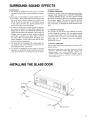
S STALLING THE GLASS DOOR
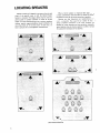
LOCATING SPEAKERS
Speaker location will depend in each case on the size and
shape of the specific room in which the Home Theater
System is installed. The diagrams below may be used as a
general guide to speaker placement in rooms of various
shapes. To avoid interference with the tv picture, speakers
without special magnetic shielding should ordinarily be
more than 0.6m (2 f t ) from the screen. In each case, i t is
best to consult the tv and loudspeaker manufacturers.
When a Center speaker is employed (See page 18). i t
is most conveniently mounted above or below the screen,
but always as close to the screen centerline as possible.
Because very low frequencies are nondirectional in
room, a subwoofer (See page 8) can usually be loca
almost anywhere convenient in the room. However, depending on room acoustics and the particular subwoofer,
some locations may be clearly superior to others. Consult
the subwoofer manufacturer for specifics.
LOCATING SPEAKERS
-
,!
CONNECTION OF SPEAKERS
Connection of 4 Speakers
+ I
MONO OUT
Monophonic Output
Terminals
I
I
OPERATE SWITCH
Normally this switch is SPEAKER AC O U T L E T
kept to the left (seen
OUTPUT (SWITCHED)
from behind).
TERMINALS
There i s one set of four speaker output terminals. Use speakers with an impedance of 8 to 16 ohms.
Normal Speaker Connection
Connection of Speaker Cables
1. If the bare speaker wire is too short, strip off
the vinyl and make the exposed wires the
same length. lomm
[318'n1
*F
EXAMPLE: With a speaker terminal on the
bottom side.
2. Press down the lever and insert the cord. Use a
Remove your finger from the lever, and pull
on the cord t o be sure that it i s properly connected.
Put the Operation Switch in the I N O R M A L 1
position.
"+" terminal for the + side of the speaker and
a "-" terminal for the side.
3. Raise the lever.
Be sure that the wire does not stick out
from the cord and come into contact with
wire of another cord, as this may damage the
equipment.
-
FUNCTION NAMES AND OPERATIONS-FRONT PANEL
Function Names and Operations
@ REMOTE SENSOR
@ Power Switch (POWER)
Use this switch to turn the power of the AVC20
on and off. After turning on, allow approximately
4 seconds to pass before using. During this time,
the FULL MUTE indicator
on the concentrated indicator panel will flash, indicating that the
set is in the stand-by mode.
@ Concentrated Indicator Panel
lndicators light up according to the operations
performed on the AVC2O.
@ SURROUND INDICATOR
Three red LEDs are displayed, depending on
the level at the AVMO speaker outputs.
Front Left Channel
This is the window used for receiving the signal
from the supplied wireless remote control unit.
BYPASS
Use this position when you wish to
obtain stereo sound without any
surround effect.
Sound is produced only from the two
front speakers.
@ SYNTHETIC STEREO
Use this switch to obtain simulated
stereo sound from monophonic signals.
Use the SYNTHETIC STEREO volume control located inside the control
panel door to adjust the stereo effect.
Front Right Channel
This function can also be used to expand a
stereo source.
Rear
Left Channel
Rear
Right Channel
@ CONCERT
SURROUND
This i s the best position for viewing
@ Volume and Balance Controls
details, refer t o page 10)
@ Input Selector Switches and lndicators
(AUDIOIVIDEO
SELECTOR)
Use these switches to select the program source.
televised concerts or old movies.
Use the CONCERT SURROUND
volume control located inside the control panel door to adjust the reverbera-
(For
When the W
E
]switch i s pressed, the
..
sound source is switched to the component
connected to the TAPE input terminals while
the video source i s provided by the A-V INPUT
whose selector switch i s pressed.
(For details, refer to page 18)
@
I
SPATIAL
SURROUND
time.
This is the best position for viewing
sports or music programs.
DOLBY
This is the best position for viewing
SURROUND movies.
0
The AVC20 is equipped with the
proper Dolby Surround decoder for
use especially with video software containing the DOLBY SURROUND
,('"or movies in which the DOLBY
,,,,,,~,,~,,,,,,
mark 00
at the end.
STEREO rnark~OImre*m~mI'"appears
The Dolby Surround system i s manufactured under
licence from Dolby Laboratories Licencing Corporation.
Refer to page 3 for more detailed information.
@ Surround Indicator Switch
(SURROUND INDICATOR)
Use this switch t o turn the SURROUND
INDICATOR on or off.
@$Synthetic Stereo Control (SYNTHETIC STEREO)
Use this control to adjust the effect when the
SYNTHETIC STEREO switch @ i s turned on.
Expansion becomes greater when turned clockwise, and lower when turned counterclockwise.
@ Concert Surround Control (CONCERT SURROUND)
Use this control to adjust the effect when the
CONCERT SURROUND button @ i s depressed.
The reverberation time is increased when
turned clockwise.
@ Input Balance Control (INPUT BALANCE)
Use this to balance the left and right channels
of the input source.
@ INPUT VOLUME
Use this control to set the maximum volume.
(Refer to page 10 for details.)
Press once to turn the SURROUND INDICATOR off if it is distracting.
@ NOISE Filter Switch (NOISE FILTER)
1
This filter reduces the hissing noise
produced when viewing old movies for
example.
MONO INPUT
Depress when using a monophonic video deck.
The STEREO indicator
will turn off.
@ FULL MUTE
Depress to cut off sound momentarily.
When dep~essed,the
indicator will light.
Press again to return t o the original volume.
@ Volume Reset Switch (VOLUME RESET)
Use this to make the volume from each speaker
equal.
As the volume will be low when this is done,
use the volume switches @ to readjust the
balance.
@ Image Enhancer Switch (IMAGE ENHANCER)
Use this switch t o make the contours of the
picture clearer.
0 3dB
0 6dB
0 OFF
* As the image enhancer makes all details of the
picture clearer, small white spots on the screen
may also stand out, thus making the picture
actually harder t o see. If this is the case, turn
the function OFF.
@ Tone Control
Treble and bass tones can be controlled for both
the front and rear speakers.
Use the FRONT control to adjust the tone of
the front speakers, and the REAR control for
the rear speakers.
Use the TREBLE and BASS controls to adjust
treble or bass.
Turn clockwise to increase the effect, or counterclockwise to decrease.
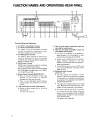
FUNCTION NAMES AND OPERATIONS-REAR PANEL
Function Names and Operations
@ A-V INPUT 1 Input/Output Terminals
@ A-V INPUT 2 InputIOutput Terminals
@
@
A-V INPUT @ and @ Input/Output Terminals
are used for connection of components on which
recording is possible, such as a video deck.
A-V INPUT 3 lnput Terminals
A-V INPUT@ lnput Terminals are used for connection of components for which only playback
is possible, such as video disc players compact disc
players, or television tuners.
PHONO lnput Terminals
PHONO lnput Terminals are used for connection
of a Phono Turntable without preamp.
NOTE: Selected input signals (including PHONO
and TAPE) appear at output jacks of A-V INPUT
1, A-V INPUT 2 and TAPE.
0 Monitor Output Terminals (MONITOR OUT)
These are used for connection to video input
terminals of color monito,rs or televisions
equipped with video input terminals.
There are two independent output terminals,
making possible the connection to two components.
@ Tape Input/Output Terminals (TAPE INIOUT)
Connect an audio cassette deck or the like to
these terminals.
(For details, refer to page 18)
@ These are front speaker preamplifier output and
main amplifier input terminals.
@ These are rear speaker preamplifier output and
main amplifier input terminals.
Use these for connection of an equalizer or
signal processor or of a pre-amplifier or main
amplifier other than those of the AVC20.
Usually, use the AVC20 with the pre-amplifier
output terminals connected to the main
amplifier input terminals with the supplied Ushaped connecting pin.
The AVC20 can also be used in the BTL mode
or as a surround processor. For details, refer t o
Pages 15 and 17.
@ Monophonic output Terminal
MONO OUT A, B
Use these outputs for connection t o a Subwoofer or center channel amplifier and speaker
( A sub-woofer will transduce only low-frequency signals, a full-range speaker will handle the
complete audio spectrum.)
The output level is approximately 1V a t a rated
input. Match with the input sensitivity of the
speaker or other component to be connected.
The output signal of terminals @), is a mixture
of the front left and right channels. When the
volume of the front speakers is high, the MONO
output level also increases. This can be used as a
center channel output.
(For details, refer to page 18).
@
Operation Selector Switch
Use this switch to select NORMAL or Balanced
Transformerless (BTL) operation.
NORMAL Operation
0 Use this position for independent operation
of the four power amplifiers.
0 This is the position in which the AVC20 is
normall y used.
0 In this position, the AVC20's output is
30W x 4.
BTL Operation
0 Use this position to use the AVC20 as a
stereo amplifier, with the four power amplifiers combined in groups of two.
0 In this position, the AVC20's output is 60W
x 2.
CAUTION
TURN OFF AVC2O POWER BEFORE
OPERATING THIS SWITCH.
(For details, refer to page 15)
@ Speaker Connection Terminals
Use these to connect speakers.
(Refer to page 5 for details.)
@ Power Cord
Plug this into an ac wall outlet. 120 Vac 60Hz.
@ Supplementary Power Outlets (AC OUTLETS)
SWITCHED
This outlet operates only when the AVC20
power is on.
Use this outlet to plug in equipment with a
maximum power consumption of 100W.
Use this outlet for example for a self-powered
subwoofer.
@ Supplementary Power Outlets (AC OUTLETS)
UNSWITCHED
These outlets can be used regardless of whether
the AVC20 power is on or not.
Use these outlets to plug in equipment with a
maximum power consumption of 100W.
WARNING
Power Consumption of Outlets
Never use the AC OUTLETS with equipment
which consumes more power than is indicated
on the panel (for example, toasters or hair
dryers). This could damage the equipment or
result in a fire.
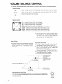
VOLUME-BALANCE CONTROL
The AVC20 is equipped with 4 built-in power amplifiers. The volume of each of these can be controlled separately.
Volume Control
m
IvoLuME
Press the upper side
to simultaneously increase the volume of all four speakers.
Press the lower side
to simultaneously decrease the volume of all four speakers.
Volume increases faster than it decreases.
Balance Control
FR
,,
RL
FL: lncreases the volume of the front left speaker.
FR: lncreases the volume of the front right speaker.
RL: lncreases the volume of the rear left speaker.
RR: Increases the volume of the rear right speaker.
FRONT: Causes the surround image to slowly travel towards the front.
REAR: Causes the surround image to slowly travel towards the rear.
Causes the surround image to slowly travel towards the left.
LEFT:
RIGHT: Causes the surround image to slowly travel towards the right.
When the volume of one of the four speakers reaches
the maximum level, the
indicator flashes. When
the volume of one of the four speakers reaches the
minimum level, the
indicator flashes.
lnput Volume
Adjusting the lnput Volume
The lnput Volume control located behind the control
panel door is used t o set the maximum volume so
that the volume of none of the speakers exceeds a
certain level.
@
First set the INPUT VOLUME control to the minimum. (Number @ inside the control panel door)
@ Use the Volume up control and set the AVC20
volume to the maximum (the If_l indicator will
flash), then bring it down 5 steps.
button 5 short times)
(Press the Volume down
@ Next gradually increase the lnput Volume until a
comfortable listening level is reached.
This is described by the following diagram.
w
.fin
+-------
LIMIT
This mark lights.
Volume you most frequently use.
+.-
-
LOWER
Greatest volume which
can be produced by
the AVCZO
Greatest volume set by
the INPUT VOLUME
control.
k4i.i-m
volume
-
no sound is produced.
This mark lights.
Dolby Surround and lnput Volume
The output level on some VHD video disc players or laser disc players is quite high. When
this is the case, DOLBY SURROUND sound may be distorted. Should this happen, lower
the INPUT VOLUME.
INPUT
VOLUME
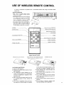
USE OF WIRELESS REMOTE CONTROL
A variety of operations are possible from a comfortable distance when, using the wireless remote
control unit.
Remote Control Sensor
.When
using the wireless remote control,
always point i t toward the remote control
sensor on the AVC20.
This wireless remote control unit uses infrared
rays. Exposure of the sensor on the AVC20
to strong fluorescent light or the like could
result in malfunction. Locate the AVC20
t o minimize exposure t o surrounding light.
.The wireless remote control unit should be
used within vertical or horizontal angles of
approximately 30' with respect to the sensor
on the AVC20 at a distance up t o 7m (20ft).
'
I
A
600
I
~
A
\
~ ~
meters
~
~
~
~
~
~
.
~
,
INSERTING BATTERIES
Remove the cover on the rear.
Insert two size "AA" batteries, pay close
attention t o the correct polarity I+and -1.
CAUTIONS ON BATTERIES
a Use size "AA" batteries.
Replace the batteries when distance of operation decreases.
The replacement interval depends on the
number of times used, but i t i s recommended that the batteries be replaced at least
once every year.
When not using the remote control unit for
an extended period of time, remove the
batteries.
Do not use an old battery with a new one or
two batteries of different types (for example,
' 0
Replace the cover.
one dry cell and one alkaline battery), as this
may result in leakage or damage t o the unit.
Should leakage occur, wipe thoroughly and
insert new batteries.
Do not short circuit, disassemble, or throw
batteries into flames.
Do not place objects on top of the remote
control unit, as the batteries will wear out if
a key i s held down.
Always strictly observe cautions written on
batteries.
Do not dispose of batteries together with
flammable garbage (where applicable).
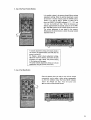
1. SURROUND-SOUNDEFFECT SELECTION
The AVC20 provides a choice of 3 surround effects,
depending upon the program or software being viewed.
For programs for which the surround effect is not necessary, such as news broadcasts, press the BYPASS button. Sound can be heard from the front speakers only.
-1Press this button for movies, etc.
-1-1
Press this button for sports programs etc.
m JCONCERTI- Press this button for concerts or old movies.
*Refer to page 3 for more detailed information.
2. Use of Volume Button
First press the RESET button (there i s no need t o keep i t
pressed down), then press the
side of the VOLUME
button. When held down, the volume gradually increases. I f
the volume becomes too loud, press the m s i d e . When the
desired volume is reached, release the button.
3. Adjusting Volume Balance
From the listening position, adjust the volume balance,
using the controls described below, to feel engulfed from all
sides while maintaining a good front stage orientation.
Readjust the overall volume.
.=]I
1-
. . . . . .Causes
the surround image
travel towards the front.
.Causes the surround image
travel towards the rear.
. . . . . . .Causes the surround image
travel towards the left.
.
.Causes the surround image
travel towards the right.
......
.. .. .
to slowly
to slowly
to slowly
to slowly
4. Use of the Preset Volume Buttons
It is possible to place in the memory three different volume
adjustment settings. When the optimal adjustment is reached as shown in number 3 above, press the STORE button.
(There is no need to keep it pressed in.) When this is
done, the PRESET VOLUME indicators (
,
and
()on the AVC20 will flash. While the indicators are
flashing (approximately 5 seconds), press one of the PRESET VOLUME buttons on the wireless remote control unit.
The volume adjustment is now stored in the memory.
Simply press the desired button to obtain the preset volume
adjustment later on.
I
,
A volume adjustment setting will remain stored in
the memory for approximately one week after the
power is turned off.
To change a preset volume adjustment setting,
adjust the volume as desired, and follow the same
procedure as in step 4 above. The previous setting
in the memory will be erased.
The preset volume adjustment setting can only be
obtained by using the remote control unit.
A
5. Use of Full Mute Button
Press this button when you wish to turn off the volume
momentarily, such as when a visitor arrives unexpectedly
or when the telephone rings. The FULL MUTE indicator
W o n the AVC20 will flash. Press the button once
again to return to the previous volume.
USE OF THE IMAGE ENHANCER SWITCH
Use of the IMAGE ENHANCER Switch
The lrnage Enhancer function i s very effective for
cleaning up fuzzy pictures, or when watching
foreign films, making movie subtitles clearer.
The switch works in three steps:
3 dB (decibels) . . . . . . . . . . For lesser effect.
0 6 dB (decibels) . . . . . . . . . For greater effect.
0 OFF. . . . . . . . . . . . . . . Switch i s tuned off.
When watching old movies or video software and
white shimmering appears on the screen, using the
lrnage Enhancer Switch to clear this up may make
the screen hard to see. Use the switch only when
the picture is improved.
0
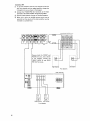
APPLICATIONS
(1) Balanced Transformerless (BTL) Mode
The AVC20 has a built-in 4-way 30W amplifier system,
but by switching to BTL operation, it can be used as a
2-way 6oW amplifier system.
BTL . . . Balanced Transformerless
Switching
Adding Amplifiers in the BTL Mode
Adding amplifiers while in the BTL mode makes possible
the creation of a sound system with total output greater
than 120 watts.
Only use this switch when the power is off.
Set the NORMALIBTL switch t o the BTL side.
Connect the speakers as shown in the diagram.
Sound is produced from the outside speaker terminals
when using the AVC20 in the BTL mode. (The rear "+"
speaker terminals become BTL
speaker terminals.)
Connection (A)
@ To use the AVC20 on the two front channels and use
the two rear channels with other amplifiers, remove the
U-shapedshort pins as shown in the diagram.
( I n order not to lose the pins, use cellophane adhesive
tape or the like to fix them to the rear panel.)
@ Connect the REAR- PRE OUT terminals to the AUX
IN terminals of the added stereo amplifier using pin
plug cables.
'I-"
I
CAUTION
TURN OFF AVCZO POWER BEFORE OPERATING
BTLSWITCH.
I
@
When this is done, the AVC20 volume control can be
operated, but the volume of the other amplifier must be
increased to match that of the AVC20.
Connection (6)
@ To use the AVC20 on the two rear channels and use the
two front channels with an added amplifier, change the
U-shapedshort pins as shown in the diagram.
@ Connect the FRONT-PRE OUT terminals to the input
terminals of the other amplifier using pin plug cables.
@ Use the outside speaker terminals for the Rear speakers.
@
When this i s done, the AVC20 volume control can be
operated, but the volume of the other amplifier must be
increased to a suitable level.
-SPEAKER
SYSTEMS-
Remove both the FRONT and
REAR short pins, and as shown
in the diagram, connect the
FRONT MAIN IN and REAR
PRE OUT terminals.
Right Channel
Left Channel
Rear Speakers
I
I
Other Amplifier
El
Right Channel
Left Channel
Front Speakers
(2) Using as Surround Processor
The AVC20 can be used by disconnecting both the front
and rear pre-amplifiers and main amplifiers.
To use the AVC20 as a surround processor with different
main amplifiers, remove the four short pins as shown in the
diagram, and use pin cords to connect the PRE OUT terminals to the input terminals of the other amplifiers.
When this i s done, the AVC20 volume control can be operated, but the volume of the other amplifiers must be
increased to a suitable level. The AVC20 amplifiers can also
be used by connecting Aux level outputs of audio devices
to the MAIN inputs.
S P E A K E R SYSTEMS-
Connect the AVC20 PRE OUT terminals to the input
terminals of the other amplifiers using cables with phono
plugs at the AVC20 side and appropriate connectors a t the
amplifier side.
Center Arnpl~fier
Center Speaker
SPEAKER
Center Speaker
With Input on the Left Channel
The left speaker output produces
sound.
-
(3) MONO OUT
Many audio/video systems are set up with a television
centered between two speakers. Sometimes, however,
if the speakers are located far away from the television, the resultant center localization can become
confusing.
To provide better center localization, connect one of
the AVC20's mono outputs to an external amplifier
and speaker, placing the speaker under, or as close
as possible to, the television.
Use a shielded magnet type speaker as the center
speaker, and keep as close as possible to the monitor
screen for best results.
When using a monophonic main amplifier as the center channel, use the AVC20's MONO output terminal
for best results.
-
(4) Use of
Input/Output Terminals 1
It is possible to add a different audio source to video
software. It is also possible to dub onto a video deck
using a different audio source.
Connect as shown in the diagram.
@ Connect a playback video component (for example, a
video disc player) to the A-V INPUT 3 Input terminals and depress the A-V INPUT 3 button on the
front panel.
Connect an audio component, such as a compact disc
player or cassette deck to the
input terminals.
When the
selector button of the front panel
i s depressed, the image from the video component
connected to
appears on the monitor. The sound
of the component connected to the m
l terminals is produced from the speakers. The audio signal
from the TAPE input overrides the audio signal from
AV INPUTS 1.2, and 3.
This can be recorded on to a video deck connected
to the output of either A-V INPUT 1 or 2.
m]
1
(5) Use of
Input/Output Terminals 2
These can be used as input/output terminals for a
signal processor such as a graphic equalizer.
Connect as shown in the diagram.
Depress one of the A-V INPUT 1-3 or PHONO to
choose which component is to be played back, and
then depress the
button.
Control by the signal processor is possible.
Refer to the signal processor instruction manual
for details on i t s use.
(4)Connections for "Use of
W
I
Lm/
Input/Output Terminals - Example 1"
Color Monitor
AVCZO Connections
I
Video Disc Player (etc.)
Video Deck IHiFil
m Audio Output TerminalFrom Video
Output
To Video Input Terminal
To Audio lnput Terminal
AVCZO
From Monitor Output Terminal
I
To Tape lnput Terminal
Audio Component
(Compact Disc Player,
Cassette Deck, etc.)
( 5 ) Connections for "Use of (TAPEl InputIOutput Terminals - Example 2"
AVC20 Rear Panel
.b From Tape Output Terminal
To Tape Input Terminal
71
Front Panel
-
Graphic Equalizer
(Rear Panel)
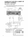
EXAMPLES OF USE WITH A VARIETY OF
DIFFERENT EQUIPMENT
(Monophonic Video Deck)
As shown in the diagrams below, video signals are supplied to the television through the antenna
line, and audio signals pass through the AVC20 to produce sound from the speakers. Turn down
the TV Volume whenever the AVC20 amps are used.
Antenna
Antenna Line
---*
Audio Signals
Pin Jack Cord
Connection to AVC2O
UHF Antenna
-
V H F Antenna
Television
Cable
Regular
Video
Deck
Set the AVC20 AUDIOIVIDEO
SELECTOR to A-V INPUT 1.
Set front panel switch to MONO or
SYNTHETIC STEREO. Choose the
one that sounds best to you.
Operate the video deck.
m For operation of the video deck, refer
to its instruction manual.
MONITOR OUT
PHONO
A-V
INPUT 1
INPUT^
INPUTS
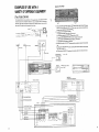
EXAMPLES OF USE WITH A VARIETY OF
DIFFERENT EQUIPMENT
(Stereo Video Deck)
USE O F INPUT SELECTOR SWITCHES
SOURCE
I
SELECTOR SWITCH
Mono
MONO
Off
Mono
SYNTHETIC STEREO
Stereo
BYPASS
[m
Stereo
CONCERT SURROUND
Stereo
SPATIAL SURROUND
stereo
DOLBY SURROUND
Television
p
x
i
1a
l
Cable
I
I
I
-- J
r
-
-3
7
-
-
II
HiFi Video Deck
rg . . l
.
-
_
I
VHF Antenna
U H F Antenna
DISPLAY
Set the AVC20 AUDIOIVIDEO SELECTOR to A-V INPUT 1.
m Set the selector switch for the format
that best suits the material according to
your personal preference.
Operate the video d e c ~ .
For operation of the video deck, refer t o
i t s instruction manual.
For antenna connection, refer t o the
video deck instruction manual.
In this example, the video signals do not
pass through the AVC20, so the image
enhancer function is inoperable.
EXAMPLES OF USE WITH A
VARIETY OF DIFFERENT EQUIPMENT
Operation of the AVC20
(Two Video Decks)
First, decide which deck is to be used primarily. In the axample below, a stereo video deck is used as
the primary deck, while a monophonic video deck i s Uxed as the secondary deck. The monophonic
video deck's video signals pass through the AVC20 into the LINE input terminal of the stereo video
deck, whose VHF output terminal is connected to the telesvision.
a
When playing back on the Stereo video deck. the3 ~ ~ 2 0 STEREO
' s
INPUT SELECTOR Switch
should
be chosen
be instead,
in the BYPASS
depending
position
on personal
(the prefereqce.
indi%ator lights). Any of the Surround switches may
Vidteo Deck
+
Video Signals
- -, Audio Signals
AVC-20
i
--
.
L--
---.--.------
For playback on the monophonic video deck:
1 Place Stereo video deck's input selector switfChto LINE,
2 Set the Stereo video deck's VIDEO/TV sel?ector switch to VIDEO.
indicator will remain off).
3 Press the AVC20's MONO INPUTswitch '(the
4 Set the AVC20's AUDIOIVIDEO SELE-~TOR
Switch to A-v INPUT 2.
5 Start playback on the monophonic vidfeo deck.
The Stereo video deck can be used-for rrecording while the monophonic video deck is being played
back.
The Monophonic video deck can be bsed for recording while the Stereo video deck is being played
back. (Press A-V INPUT 1 .)
For instructions on playback and recording on the video decks, refer to their instruction manuals.
B
Set t o "LINE,,
TV-
ST:
rLlNE
Video Deck 2
(For Playback Only) Monophonic
Video Deck 1 (Stereo)
1 1
A
1 1 1 1
II1 I
F r o m Video Output Termirtal
L
T o Video lriput Terminal
From Audio Output Terminal
T o Audio Input Terminal
L
A
-SEIKLASYSTEMS-
C
OUTLETS-
]
EXAMPLES OF USE WITH A VARIETY OF
DIFFERENT EQUIPMENT
Operation of Video Deck 1 (HiFi)
T
\
I
~SO
dLINE
(Video Deck and Video Disc Player)
The video disc player's video signals entering the AVC20, are sent from the AVC20 output terminals
to the video deck's LINE input terminals, and then from the video deck's VHF terminal to the television.
Video Disc
,
,
,
,
.
.
c
d
7
f
q
-
-
+
I
I
Video Signals
Audio Signals
Video Deck
Antenna
Line
- - - - - - - - - - - - - - - - - - .- - - -
-
a
3
Operation of AVC2O
2 Set the VIDEO/TV Selector
AVC20 Connections
u
V H F Antenna
U H F Antenna
Color Television
1 When playing back on the video disc player, press A-V INPUT 3 button.
2 The video deck can be used for recording while playing back the video disc player.
3 To play back a recorded video tape, press the A-V INPUT 1 button.
For instructions on playback or recording on the video deck, refer to i t s instruction manual.
Video Disc Player
(MU
,om,
SWITCHED
,MU
lmwl
,MU
UNSWITCHED
,Om8
EXAMPLES OF USE WITH A VARIETY OF
DIFFERENT EQUIPMENT
(TV Equipped with Video lnput Terminal)
This combination brings out the best in the AVC20. Output from all audiolvideo equipment i s input
to the AVC20, the video signals are sent from the Monitor Output Terminal to the television's Video
lnput Terminal, and the audio signals are sent to the speakers.
T V with Video lnput Terminal
To Video lnput Terminal
Video Signal
Audio Signal
Monitor
Output
When using a television equipped with a video
input terminal, set the VIDEOITV Selector
Switch to VIDEO.
Equipment
i
I
I
Color Monitor, TV with Video lnput Terminal, etc.
AVCZO Connections
For connection of antennas, refer t o page 20 or the video deck's instruction manual.
Video Deck (HiFi)
Video Disc Player, etc.
L
EXAMPLES OF USE WITH A VARIETY OF
DIFFERENT EQUIPMENT
(Overall Connections)
Connect equipemrnt for playback only, such as a TV
tun((
video disc kplayer, here for best results.
Connect equipment for playback and recording, such
as a video deck, as below for best results.
E X : Video Disc Player
Color Monitor or
T V with Video
Input Terminal
Color Monitor
To AC outlet A C l 2 0 V . 60Hz
o For speaker connection, refer to page 5.
o For use with BTL operation, refer to page
Speaker
1
Center Channel
Arnplif ler
1
Refer to page 18.
J
Plug the self-powered Subwoofer into the AVC2O
SWITCHED AC O U T L E T .
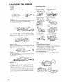
CAUTIONS ON USAGE
Take Care Wllen Installing
For Safety
Do n o t use the AVC2O i n such places as follows:
Power Source
Connect t o a household power ac outlet.
c o l d places
(
I4O0F1)
~5Oc
/.
~
,
Places
i~n which~ vibrations
l
are strong
Place i n which magnetic
Hot places (above 400C
[105OF]) or i n direct
force is generated
Wet or humid places
Places i n which ventilation
Power Cord
D o n o t bend or twist the power cord o r place heavy objects o n t o p
of it. A damaged c o r d may result i n fire or electric shock.
D o N o t Open
Do not remove the cab~net,as this is both dangerous and could
damage the AVCZO. Leave inspection and service t o authorized
service personnel.
Places i n which dust. grease
or smoke are present.
I
/
Unstable places. (Avoid
plac~ngon unsteady stands)
Handling
......
When N o t A t Home
When not using the A V C 2 0 for an extended period of time, such as
when traveling, be sure t o unplug the AVC20 from the power
Problems
Should any irregular noise, smell, or smoke be discovered, turn o f f
the power switch, unplug, and contact your dealer or qualified
service personnel.
Normal Care
Cleaning the Cabinet
.To clean the cabinet and f r o n t panel, wipe gently w i t h a soft
cloth (flannel for example). For tough dirt, apply medium strength
detergent diluted i n water t o a a soft cloth, wring o u t thoroughly,
wipe o f f dirt, then wipe w i t h a dry cloth.
If the surface o f the cabinet comes in contact w i t h a volatile
substance such as benztne, thinner, o r insecticide, or i f wiped with
a chemical rag or the like, it could be damaged, or the paint could
peel off
D o n o t block the ventilation openings.
Ventilation openings i n the cabinet are designed t o prevent overheating o f internal parts. D o not place a tablecloth or cover on
t o p o f the AVC20, or place the AVC20 o n a blanket.
D o n o t place against a wall.
Keep at a distance of at least 10 c m 14 in.) from the wall.
D o n o t place heavy objects o n t o p o f the AVC2O.
F o r transporting and storage,
Avoid excessive shocks. When moving, turn the power switch off.
Measures
Cause
Symptom
1
= Power does not come
a Power plug is not connected properly to an ac outlet.
l
Power switch is off.
l
Plug
No sound or picture
is produced
a Connection cords are disconnected.
a Connection cords are connected improperly.
a The position of the input selector switch does
not match the input of the component being
used.
a Connect firmly in the socket.
a Check the connections.
l
Change the switch to match the input.
No sound is produced
a The input selector switch
on.
T h e F U L L MUTE switch is on. (
flashes)
a Balance adjustment is incorrect.
on
No SURROUND is
produced
-1
button is
indicator
in firmly.
lPress power switch on.
h turn off.
a Press the P T A ~ E s w i t c to
.Press the F U L L MUTE switch to turn off.
a Press the RESET button, then adjust the volume.
*Depress one of the CONCERT, SPATIAL, or
DOLBY switches.
The BYPASS button has been depressed.
l
lFor
monophonic audio input, when the MODE
switch is set to MONO, sound is very weak
when in the DOLBY position.
After a power outage, operation of the A VC20 may be irregular. Turn the power off for a moment, then turn back on.
SPECIFICATIONS
Amplifier Section
Rated Output (all channels driven, Main Amplifier Input)
In Normal Operation . . . . . . . . Front . . . . . 30W + 30W
(20 - 20 kHz 8 Ohm)
Rear . . . . . . 30W + 30W
(20 20 kHz 8 Ohm)
I n B T L Operation . . . . . . 60W + 60W (20 - 20 kHz 8 Ohm)
Harmonic Distortion
I n Normal Operation (at rated output) . . . . . . . . . . <0.1%
Frequency Response . . . . . . . . . . . . lOHz - 40kHz (+O, -2dB)
(Main Amplifier Input)
-
BASS . .
TREBLE
SN Ratio (IHF shortcircuit,"A" network)
AudiolVideo Input (BY PASS) . . . . . . . . .
Main Amplifier Input . . . . . . . . . . . . . .
Tone Control
...............
......
......
AlOdB
*lodB
. . . . . . . 90dB
. . . . . . lOOdB
Input/Output Section
lnput Terminal (Sensitivity, lnput Impedance)
A-V INPUT O , IZj, B . . . . . Video . . . . lVpp175 Ohm
Audio . . 150mVl47k Ohm
8mV/47k Ohm
PHONO . . . . . . . . . . . . . . . . . . . . . .
TAPE . . . . . . . . . . . . . . . . . . . . . . . 150mVl47k Ohm
Main Amplifier Input . . . . . . . . . . . . . . . . 1Vl20k Ohm
Output Terminals (Output Level. Output Impedance)
AudioIVideo
. . . . . . . . Video . . . . 1Vpp175 Ohm
AudioIVideo
[Z1 . . . . . . . . Audio
150mV12.2k Ohm
Monitor Output (1, 2) . . . . . . . . . . . . . . . . 1VppI75 Ohm
Pre-Amplifier Output . . . . . . . . . . . . . . . . . 1V l l k Ohm
Monophonic Output A, B . . . . . . . . . . . . . . 1Vl500 Ohm
m,
W,
l
The
.
above specifications are subject to change without notice.
Others
Power source Voltage . . . . . . . . .
Power Consumption
Supplementary Power Source Outlets
.......
120 Vac. 60Hz
. . . . . . . . . . . . . . . . . . . . . . . . 300W
.....
Switched: 1 (100W)
Unswitched : 2 (100W x 2 )
. . . . . . . 430 x 110 x 340 m m
(16-15116 x 4-5/16 x 13-318 in.)
. . . . . . . 9.5 kg (20 Ib. 14 02:)
.......................
Outer Dimensions ( W x H x D)
Weight
..
................
Accessories
Owner's Manual . . . . . . . . . . . . . . . . . . . . . . : . . . . .
Wireless Remote Control Unit . . . . . . . . . . . . . . . . . . . .
AA Batteries (SUMS) . . . . . . . . . . . . . . . . . . . . . . . . .
Pin Plug Cord for Video Signals . . . . . . . . . . . . . . . . . . .
Glass Door . . . . . . . . . . . . . . . . . . . . . . . . . . . . . . .
Rubber Bushing . . . . . . . . . . . . . . . . . . . . . . . . . . . .
Screw . . . . . . . . . . . . . . . . . . . . . . . . . . . . . . . . . .
1
1
2
2
1
2
2