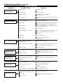
1
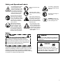
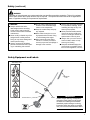
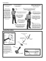
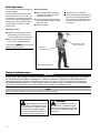
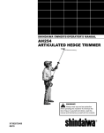
SHINDAIWA OWNER’S/OPERATOR'S MANUAL
AHS242 ARTICULATED
HEDGE TRIMMER
WARNING!
Always wear eye and ear
protection when operating
this machine! To minimize the risk of
injury to yourself and others, read this
manual and familiarize yourself with
its contents.
X7502801200
06/10
Introduction
The Shindaiwa AHS242 Articulated
Hedge Trimmer is designed and built
to deliver superior performance and
reliability without compromise to quality, comfort, safety or durability.
Shindaiwa's engines represent the
leading edge of high-performance,
engine technology, delivering exceptionally high power with remarkably
low displacement and weight. As an
owner/operator, you'll soon discover
for yourself why Shindaiwa is simply
in a class by itself!
Contents
PAGE
IMPORTANT!
The information contained in these
instructions describes machines available at the time of publication.
Echo Inc. reserves the right to make
changes to products without prior
notice, and without obligation to make
alterations to units previously manufactured.
WARNING!
The engine exhaust from this
product contains chemicals known to
the State of California to cause cancer, birth defects or other reproductive harm.
PAGE
PAGE
Mixing fuel.....................................10
Safe Operation..............................14
Product Description.........................6
Filling the fuel tank........................ 11
Maintenance..................................14
Specifications..................................7
Starting the Engine ....................... 11
Long Term Storage........................19
Emission Control.............................7
Stopping the Engine......................13
Troubleshooting Guide..................20
Assembly.........................................8
Checking Unit Condition................13
Warranty Statement.......................23
Safety .............................................3
IMPORTANT!
The procedures described in this manual are intended to help you get the most from your unit as well as to protect you and
others from harm. These procedures are guidelines for safe operation under most conditions, and are not intended to replace
any safety rules and/or laws that may be in force in your area. If you have questions regarding your power tool, or if you do not
understand something in this manual, your Shindaiwa dealer will be glad to assist you. You may also contact Shindaiwa at the
address printed on the back of this Manual.
Attention Statements
Throughout this manual are special “attention statements”.
DANGER!
A statement preceded by the triangular attention symbol and the word “DANGER” contains information that should be acted upon to prevent serious injury or
death.
WARNING!
A statement preceded by the triangular attention
symbol and the word “WARNING” contains information
that should be acted upon to prevent serious bodily injury.
2
IMPORTANT!
A statement preceded by the word “IMPORTANT” is one
that possesses special significance.
CAUTION!
A statement preceded by the word “CAUTION”
contains information that should be acted upon to
prevent mechanical damage.
NOTE:
A statement preceded by the word “NOTE” contains information
that is handy to know and may make your job easier.
Safety and Operational Labels
An articulated hedge trimmer
has the potential to cause
serious personal injury to the
operator or bystanders if misused, abused or mishandled.
You must observe all special
safety instructions to reduce
the risk of personal injury.
Read and follow this manual,
make sure anyone using the
trimmer does likewise. Failure
to do so could result in serious
personal injury or machine
failure. Keep this manual for
future reference.
The blades / cutting attachments are SHARP! Handle
with care.
Wear non-slip heavy-duty
gloves.
Safety tip shoes or boots
with non-slip sole should be
worn.
33 ft
10 M
Be aware of the danger of
falling debris.
This product conducts electricity. Keep the product and/
or operator a minimum distance of 33 feet (10 meters)
away from electrical sources
and power lines.
Always wear a hard hat to
reduce the risk of head injuries during operation of this
machine. In addition, always
wear eye and hearing protection. Shindaiwa recommends
wearing a face shield as additional face and eye protection.
WARNING ! Surface can
be hot. Always wear gloves
when handling this unit.
Keep bystanders at least
50 feet (15 meters) away
from the operating trimmer
to reduce the risk of being
cut by the cutting blades or
struck by falling objects or
thrown debris.
Safety
DANGER!
THE ARTICULATED HEDGE TRIMMER IS
NOT INSULATED AGAINST ELECTRICAL SHOCK!
Approaching or contacting electrical lines with the
trimmer could cause death or serious injury. Keep the
trimmer at least 10 meters away from electrical lines
or branches that contact electrical lines.
An articulated hedge trimmer has the potential to cause serious personal injury to the operator or bystanders if misused,
abused or mishandled. To reduce the risk of injury, you must
maintain control at all times, and observe all safety precautions during operation. Never permit a person without training
or instruction to operate this hedge trimmer!
WARNING!
Do not make unauthorized modifications
or alterations to your articulated hedge trimmer or
its components.
WARNING!
Never operate this tool or any other power
equipment if you are tired, ill, or under the influence of alcohol, drugs, or any substance that
could affect your ability or judgement.
3
Operating Precautions
■■Never transport the articulated
hedge trimmer or leave it unattended with the engine running.
An engine that’s running could be
accidently accelerated causing the
blades to oscillate.
■■Make sure that the blade cover is in
place when transporting or storing
the articulated hedge trimmer.
■■Always make sure that the cutter attachment and all handles and
guards are properly installed and
firmly tightened before operation.
■■Inspect for broken, missing or
improperly installed parts or
attachments.
■■Never use a cracked or warped cutter or cutter bar: replace it with a
serviceable one and make sure it
fits properly.
■■Make sure there are no missing or
loose fasteners, and that the stop
switch and throttle controls are working properly.
WARNING!
■■Make sure there is always good
ventilation when operating the articulated hedge trimmer. Fumes from
engine exhaust can cause serious injury or death. Never run the
engine indoors!
■■Never smoke or light fires near the
hedge trimmer. Keep the unit away
from excessive heat. Engine fuel is
very flammable and fire could lead
to serious personal injury or property damage.
■■Make sure the cutters are correctly adjusted before operating the
articulated hedge trimmer (see the
section ”Cutter Blade Adjustment”
for cutter adjustment procedures).
Never attempt cutter adjustment
with the engine running!
■■Before starting the engine, make
sure the cutter is not contacting
anything.
■■Always confirm safe operation
when using the machine.
■■Immediately stop the engine with
the stop switch if the machine suddenly begins to vibrate or shake.
■■Always stop the engine immediately and check for damage if
you strike a foreign object or if the
machine becomes tangled. Do not
operate with broken or damaged
equipment.
■■When cutting a branch that is
under tension, be alert for springback so that you will not be struck
by the moving branch.
■■If a cutter should bind fast in a cut,
shut off the engine immediately.
Push the branch or tree to ease
the bind and free the cutter.
■■Always stop the engine and allow
it to cool before refueling. Avoid
overfilling and wipe off any fuel
that may have spilled.
■■To reduce fire hazard, keep the
engine and muffler free of debris,
leaves, or excessive grease.
■■Keep a Solid Stance. Maintain
footing and balance at all times.
Do not stand on slippery, uneven
or unstable surfaces. Do not work
in odd positions or on ladders. Do
not over reach.
WARNING!
Moving parts can amputate fingers or cause severe injuries. Keep hands, clothing and loose objects away
from all openings.
•ALWAYS stop engine, disconnect spark plug, and make sure all moving parts have come to a complete stop before removing obstructions, clearing debris, or servicing unit.
•DO NOT start or operate unit unless all guards and protective covers are properly assembled to unit.
•NEVER reach into any opening while the engine is running. Moving parts may not be visible through openings.
WARNING!
Engine exhaust IS HOT, and contains Carbon Monoxide (CO), a poison gas. Breathing CO can cause
unconsciousness, serious injury, or death. Exhaust can cause serious burns. ALWAYS position unit so that
exhaust is directed away from your face and body.
WARNING!
Hedge Clipper blades are very sharp. Touching them may lead to severe personal injury. Avoid touching
blades whenever possible, and always wear gloves to protect hands
4
Safety (continued)
WARNING!
Operation of this equipment may create sparks that can start fires around dry vegetation. This unit is equipped
with a spark arrestor and a spark arrestor may be required. The operator should contact local fire agencies for
laws or regulations relating to fire prevention requirements.
CAUTION!
■■Always maintain the articu-
lated hedge trimmer according
to this owner’s manual and follow the recommended scheduled
maintenance.
■■Never modify or disable any of the
hedge trimmer’s safety devices.
Doing so may cause damage and
lead to personal injury.
■■Always use genuine Shindaiwa
parts and accessories when repairing or maintaining this machine.
■■Do not make unauthorized modi-
fications to the articulated hedge
trimmer or its components.
■■Keep the cutters sharp and properly adjusted.
■■Never allow the engine to run at
high speed without a load. Doing
so could damage the engine.
■■When transporting the hedge
trimmer in a vehicle, tie it down
securely to prevent fuel spillage or
damage to the machine.
■■Always stop the engine and allow
it to cool before refueling. Avoid
overfilling and wipe off any fuel
that may have spilled.
■■Never place flammable material
close to the engine muffler and
never run the engine without the
spark arrestor screen in place.
■■Always clear your work area of
trash or hidden debris to help
ensure good footing.
■■Keep the articulated hedge trimmer as clean as possible. Keep it
free of loose vegetation, mud, etc.
Safety Equipment and Labels
Shaft Safety Label
Cutter Blade
Cover
Stop
Switch
Throttle Interlock
Handle
IMPORTANT!
Caution, Danger, Warning, and Operation
Information Labels: Make sure all information labels are undamaged and readable.
Immediately replace damaged or missing
information labels. New labels are available
from your local authorized Shindaiwa dealer.
5
Operator Safety
Always wear a hard hat
to reduce the risk of head
injuries during operation of
this machine.
This machine is designed
for trimming hedges. Do
not use this machine for
other purposes.
ALWAYS clear your work area
of trash or hidden debris that
could be thrown back at you or
toward a bystander.
Always wear eye and hearing protection.
Shindaiwa recommends wearing a
face shield as additional face and eye
protection.
ALWAYS protect
yourself from hazards
such as thorny brush
and flying debris by
wearing gloves and
close fitting clothing
that covers arms and
legs. Never wear
shorts. Don't wear loose
clothing or items such
as jewelry that could
get caught in machinery
or underbrush. Secure
long hair so it is above
shoulder level.
NEVER allow children to
use the unit. Avoid operating
near bystanders or when
children are nearby.
Always operate with both hands
firmly gripping the machine.
Keep a proper footing
and do not overreach—
maintain your balance
at all times during
operation.
Keep bystanders at least
15 meters away from the
operating trimmer to reduce
the risk of being struck by
falling objects or thrown
debris.
ALWAYS be aware of
your surroundings and
alert to any danger that
you may not hear due to
machine noise.
ALWAYS wear close-fitting
clothing. Gloves offer added
proctection and are strongly
recommended. Do not wear
clothing or jewelry that could
get caught in machinery.
Wear sturdy footwear with nonslip
soles to provide good footing.
Steel-toed safety boots are
recommended. Never operate
machine bare-footed.
Product Description
Spark
Plug
Air Filter
Assembly
Hedge Trimmer Cutter
Assembly
Ignition
Cutter Assembly
Adjustment Lever
Cutter Blade
Cover
Fuel Tank
ThrottleTrigger
Handle
Fuel Tank Guard
Powerhead Assembly
Using the illustration as a
guide, familiarize yourself
with the Shindaiwa AHS242
articulated hedge trimmer
and its various components.
Understanding your machine
helps ensure top performance, longer service life, and
safer operation.
6
Outer
Tube
Handle
Grip
Latch Release
Fuel Tank
Guard
Latch Lock
Gearcase
Hedge Trimmer
Cutter Assembly
Cutter Bar and
Cutter Blades
Specifications
Model
AHS242
Engine type
2-cycle, air cooled, vertical cylinder
Dimensions (L x W x H)
1682 mm (66.2 in) x 248 mm (9.76 in) x 245 mm (9.6 in)
Weight
5.99 Kg (13.2 lb)
Bore x stroke
33 x 28 mm/1.3 x 1.1 in.
Displacement
23.9 cm3/1.46 cu. in.
Fuel/oil ratio
50:1 with *ISO-L-EGD or JASO FD class engine oil
Carburetor type
Diaphragm-type
Fuel tank capacity
690 ml/ 23.3 oz.
Ignition
One-piece electronic, C.D.I.
Spark plug
NGK BPMR8Y
Electrode Gap
0.6 mm/ .024 in.
Torque
150-170 kgf cm / 130 - 150 in • lbf
Air cleaner type
Non-reversible double layer felt
Starting method
Recoil
Stopping method
Slide switch
Transmission type
Automatic, centrifugal clutch w/bevel gear
Cooling System
Blade Length
Cutter Drive
Gear Lubricant
Forced Air
568 mm/22.4 in.
Spur Gear
Lithium Based Grease
Idle Speed
3,000 RPM
Clutch Engagement Speed
4,000 RPM
Wide Open Throttle Speed (W.O.T.)
11,800 RPM
Specifications are subject to change without notice.
Emission Control (Exhaust & Evaporative)
EPA 2010 and Later and/or C.A.R.B. TIER III
The emission control system for the engine is EM/TWC (Engine Modification and 3-way Catalyst) and for the fuel tank
the Control System is EVAP (Evaporative Emissions) or N (for nylon tank). Evaporative emission may be applicable to
California models only.
An Emission Control Label is located on the unit. (This is an EXAMPLE ONLY; information on label varies by engine FAMILY).
PRODUCT EMISSION DURABILITY (EMISSION COMPLIANCE PERIOD)
The 300 hour emission compliance period is the time span selected by the manufacturer certifying the engine
emissions output meets applicable emissions regulations, provided that approved maintenance procedures are
followed as listed in the Maintenance Section of this manual.
7
Assembly
Prior To Assembly
Before assembling, make sure you
have all the components required for a
complete unit:
■■Unit assembly
■■Cutter blade cover
Handle
This unit comes with the handle installed. It can be re-adjusted for operator comfort in the following manner.
■■Kit with this manual and tool kit for
routine maintenance.
Carefully inspect all components for
damage.
IMPORTANT!
The terms “left”, “left-hand”, and “LH”;
“right”, “right-hand”, and “RH”; “front”
and “rear” refer to directions as viewed
by the operator during normal operation.
Socket-head
Capscrews
Handle
Throttle
Assembly
1. Loosen the four socket-head capscrews.
2. Rotate/slide handle assembly to
best position for operator comfort,
usually 25 cm (10 in.) ahead of the
throttle assembly.
Outer Tube
3. Tighten socket-head capscrews in a
crisscross manner.
Position the handle on the outer tube as shown
Mounting Bracket
Adjusting the Hedge Trimmer Cutter Assembly
Adjustment Lever
WARNING!
Latch Lock
Never run the engine
when adjusting the cutter assembly.
WARNING!
Grasp the outer tube near the handle
■■The cutter blades are very
sharp. Do not grasp the blades
with your hands. Always use
gloves when working near the
cutter assembly.
■■Do not allow the blades to contact your body.
■■Do not touch the cutter blades
when the engine is running.
The blades can oscillate even
if the engine is idling.
1. Position the hedge trimmer on a flat,
level surface.
2. With your right hand, grasp the outer
tube near the handle. With your left
hand, grip the adjustment lever on
the cutter assembly.
8
Latch Lock
Latch Release
Press the latch lock
Pivot the cutter assembly using the
adjustment lever...
Adjustment Lever
Make sure the latch lock and the latch release
return securely to the locked position
IMPORTANT!
The latch lock provides an interlock to
help prevent inadvertent depression of
the latch release.
5. Release the latch lock and the latch
release. Make sure the latch lock
and the latch release return securely
to the locked position.
3. With the index finger of your left
hand, press the latch lock. With your
left thumb, press the latch release.
6. Remove the cover from the cutter blade. The engine now may
be started (refer to the section
”Starting the Engine”.)
4. While holding the latch release
down, pivot the cutter assembly
away from you using the adjustment
lever until it is at the desired cutting
angle.
Assembly (continued)
Travel limiter and adjustment range
NOTE:
This articulated hedge trimmer is
equipped with a travel limiter that prevents the cutter assembly from rotating
outside of the 90°- 225° range.
The cutter assembly can be adjusted
to 10 different positions ranging from
90° to 225° from the outer tube as
shown. Always make sure the latch
lock is securely locked after each
adjustment.
WARNING!
225°
Travel Limiter
135°
90°
The travel limiter prevents the cutter
assembly from rotating outside of the 90°225° range
Always make sure the latch
lock is securely locked after each
adjustment.
The cutter assembly can be adjusted to 10
different positions
Adjusting cutter assembly for storage or transportation
1. With the engine off, install the
blade cover onto the blade.
2. Using the procedures described
above, rotate the cutter assembly so it is parallel to the tube.
Make sure the latch lock and the
latch release return securely to a
locking position.
Transport / storage position
WARNING!
Never run the engine when
adjusting the cutter assembly.
Make sure the blade cover is in place before
storing or transporting
3. Make sure the blade cover is in place
on the blade before storing or transporting.
Throttle lever free play
The throttle lever free play should be approximately 4 - 6 mm. Make sure that the
throttle lever operates smoothly without binding. If it becomes necessary to adjust
the lever free play, follow the procedures and illustrations that follow.
1. Loosen the air cleaner cover knob(s) and remove the air cleaner cover.
2. Loosen the lock nut on the cable adjuster. Turn the cable adjuster in or out as
required to obtain proper free play 4 - 6 mm.
4 - 6 mm
Throttle lever free play
3. Tighten the locknut.
4. Reinstall the air cleaner cover.
Cable
Adjuster
Lock
Nut
Rotate cable
adjuster in or
out to obtrain proper free play
9
Mixing Fuel
WARNING!
Alternative fuels, such as E15 (15% ethanol), E-85 (85% ethanol) or any fuels not meeting Shindaiwa
requirements are NOT approved for use in Shindaiwa gasoline engines. Use of alternative fuels may cause
performance problems, loss of power, overheating, fuel vapor lock, and unintended machine operation, including,
but not limited to, improper clutch engagement. Alternative fuels may also cause premature deterioration of fuel
lines, gaskets, carburetors and other engine components.
Fuel Requirements
Gasoline - Use 89 Octane [R+M/2] (mid grade or higher) gasoline known to be good quality. Gasoline may contain
up to 10% Ethanol (grain alcohol) or 15% MTBE (methyl tertiary-butyl ether). Gasoline containing methanol (wood
alcohol) is NOT approved.
2 Stroke Mixture Oil - A 2-stroke engine oil meeting ISO-L-EGD (ISO/CD 13738) and J.A.S.O. M345/FD standards
must be used. Shindaiwa OneTM 2-Stroke Oil is strongly recommended as it meets this standard and is specifically
formulated for use in all Shindaiwa 2-stroke engines. Engine problems due to inadequate lubrication caused by failure to use an ISO-L-EGD (ISO/CD 13738) and J.A.S.O. M345/FD certified oil will void the engine warranty.
For increased engine protection, Shindaiwa recommends using Shindaiwa Red ArmorTM engine oil to protect the engine from
harmful carbon build up, maintain engine performance, and increase engine life. Shindaiwa Red ArmorTM engine oil exceeds
ISO-L-EGD and J.A.S.O. M345/FD performance requirements.
IMPORTANT!
Shindaiwa One 2-Stroke oil or Red ArmorTM engine oil may be mixed at 50:1
ratio for application in all Shindaiwa engines sold in the past, regardless of ratio
specified in those manuals.
Examples of 50:1 mixing quantities
TM
IMPORTANT!
Stored fuel ages. Do not mix more fuel than you expect to use in thirty (30)
days, ninety (90) days when a fuel stabilizer is added. Use of unmixed, improperly mixed, or stale fuel, may cause hard starting, poor performance, or severe
engine damage and void the product warranty. Read and follow instructions in
the Long Term Storage section of this manual.
Handling Fuel
DANGER
Fuel is VERY flammable. Use extreme care when mixing, storing or handling or serious personal injury may result.
•Use an approved fuel container.
•DO NOT smoke near fuel.
•DO NOT allow flames or sparks near fuel.
•Fuel tanks/cans may be under pressure. Always loosen fuel caps slowly allowing pressure to equalize.
•NEVER refuel a unit when the engine is HOT or RUNNING!
•DO NOT fill fuel tanks indoors. ALWAYS fill fuel tanks outdoors over bare ground.
• DO NOT overfill fuel tank. Wipe up spills immediately.
•Securely tighten fuel tank cap and close fuel container after refueling.
•Inspect for fuel leakage. If fuel leakage is found, do not start or operate unit until leakage is repaired.
•Move at least 3m (10 ft.) from refueling location before starting the engine.
10
Mixing Instructions
1. Fill an approved fuel container with half of the
required amount of gasoline.
2. Add the proper amount of engine oil to gasoline.
3. Close container and shake to mix oil with gasoline.
4. Add remaining gasoline, close fuel container, and
remix.
IMPORTANT!
Spilled fuel is a leading cause of hydrocarbon emissions.
Some states may require the use of automatic fuel shutoff containers to reduce fuel spillage.
After use
• DO NOT store a unit with fuel in its tank. Leaks can
occur. Return unused fuel to an approved fuel storage container.
Storage - Fuel storage laws vary by locality. Contact
your local government for the laws affecting your area.
As a precaution, store fuel in an approved, airtight
container. Store in a well-ventilated, unoccupied building, away from sparks and flames.
IMPORTANT!
Stored fuel may separate. ALWAYS shake fuel container thoroughly before each use.
Filling the Fuel Tank
WARNING!
Minimize the Risk of Fire
■■NEVER smoke or light fires near
the engine.
■■ALWAYS stop the engine and
allow it to cool before refueling.
■■ALWAYS Wipe all spilled fuel and
move at least 3 meters (10 feet)
from the fueling point and source
before starting.
■■NEVER place flammable material
close to the engine muffler.
■■NEVER operate the engine
without the muffler and spark
arrester screen in place and in
good working condition.
■■FUEL IS HIGHLY FLAMMABLE.
■■ALWAYS store gasoline in
a container approved for
flammable liquids.
■■ALWAYS inspect the unit for
fuel leaks before each use.
During each refill, check that
no fuel leaks from around
the fuel cap and/or fuel tank.
If fuel leaks are evident, stop
using the unit immediately.
Fuel leaks must be repaired
before using the unit.
■■ALWAYS move the unit
at least 3 meters (10 feet)
away from a fuel storage
area or other readily flammable materials before
starting the engine.
1. Place the unit on a flat, level surface.
2. Clear any dirt or other debris from
around the fuel filler cap.
CAUTION!
Slowly remove the fuel cap only
after stopping the engine.
3. Remove the fuel cap, and fill the
tank with clean, fresh fuel.
4. Reinstall the fuel filler cap and
tighten firmly.
5. Wipe away any spilled fuel before
starting engine.
Starting the Engine
IMPORTANT!
Engine ignition is controlled by a two position switch mounted on the throttle housing labeled, “I” for ON or START and “O” for OFF
or STOP.
NOTE:
The blade cover is used for transportation and storage. Remove blade cover before using the unit.
WARNING!
Never start the engine from the operating position.
11
Starting the Engine (continued)
1. Slide the ignition switch to the “ON”
position.
2. Press the primer bulb until fuel can
be seen flowing in the transparent
return tube.
ON
Primer Bulb
IMPORTANT!
The primer system only pushes fuel
through the carburetor. Repeatedly
pressing the primer bulb will not flood
the engine with fuel.
Slide the ignition switch to the “ON” position
Press the primer bulb
3. Set the choke lever to the CLOSED
position if engine is cold.
4. While holding the outer tube firmly
with left hand. Use your other hand
to slowly pull the recoil starter
handle until resistance is felt, then
pull quickly to start the engine.
Closed
CAUTION!
Do not pull the recoil starter to the
end of the rope travel. Pulling the
recoil starter to the end of the rope
travel can damage the starter.
Set the choke lever to CLOSED
WARNING!
The cutting blades may move (oscillate) when the engine is started.
Keep away from the cutter assembly while starting the engine!
Open
5. When the engine starts, slowly
move the choke lever to the
”OPEN” position. (If the engine
stops after the initial start, close the
choke and restart.)
IMPORTANT!
If the engine fails to start after several
attempts with the choke in the closed
position, the engine may be flooded
with fuel. If flooding is suspected, refer
to the ”Starting a Flooded Engine”
section of this manual.
12
Move choke lever to OPEN
position when engine starts
...and pull recoil
starter handle upward
Starting the Engine (continued)
When the Engine Starts...
■■After the engine starts, allow the
engine to warm up at idle 2 or 3
minutes before operating the unit.
■■If the engine does not continue to
run, repeat the appropriate cranking procedures for a cold or warm
engine.When the engine starts,
clear excess fuel from the combustion chamber by accelerating the
engine several times with the throttle lever.
■■Advancing the throttle makes the
cutting attachment move faster;
releasing the throttle permits the
attachment to stop moving. If the
cutting attachment continues to
move when the engine returns to
idle, carburetor idle speed should
be adjusted (see “Adjusting Engine
Idle”.).
If the engine does not start
■■Repeat the appropriate starting procedure for a cold or warm engine.
■■If the engine still fails to start,
use the procedures for “Starting a
flooded engine.”
Starting a flooded engine
WARNING!
Burn danger from hot engine!
1. Slide the ignition switch to the “I” (ON) position.
2. Open the choke, put the throttle lever in the full throttle position, then clear excess fuel from the combustion chamber by
cranking the engine several times.
3. If the engine still fails to start or fire, refer to the troubleshooting flow chart at the end of this manual.
Stopping the Engine
Idle the engine briefly before stopping
(about 2 minutes), then slide the ignition
switch to the “O” (Engine OFF) position.
OFF
WARNING!
The cutting attachment can
continue moving after the engine is
stopped!
Slide ignition switch to OFF
Checking Unit Condition
NEVER operate the unit with the protective devices removed!
Use only authorized Shindaiwa parts
and accessories with your Shindaiwa
hedge trimmer. Do not make modifications to this unit without written approval from Shindaiwa.
ALWAYS make sure the cutting attachment is properly installed and firmly
tightened before operation.
NEVER use a cracked or warped cutting
attachment: replace it with a serviceable
one.
ALWAYS make sure the cutting attachment fits properly into the appropriate
attachment holder. If a properly installed attachment vibrates, replace the
attachment with new one and re-check.
ALWAYS stop the engine immediately
and check for damage if you strike a foreign object or if the unit becomes tangled.
Do not operate with broken or damaged
equipment.
NEVER allow the engine to run at high
speeds without a load. Doing so could
damage the engine.
NEVER operate a unit with worn or
damaged fasteners or attachment
holders.
WARNING!
A cutting attachment shield or other
protective device is no guarantee
of protection against ricochet. YOU
MUST ALWAYS GUARD AGAINST
FLYING DEBRIS!
13
Safe Operation
This machine is designed especially for
trimming hedges.
Never use this machine for any other
purposes. Never try to cut stones, metals, plastics or any other hard objects.
Using this Articulated Hedgetrimmer for
other purposes than trimming hedges
may damage the machine or cause
serious injury.
Before trimming:
■■Wear suitable protective clothing
and equipment. See the “Safety”
section for information.
■■Rest when you feel fatigued.
■■Never stand directly underneath the
■■Choose the best working position
for safety against the falling objects
(branches, etc.).
■■Start the engine.
branch you are cutting. Be aware of
falling branches. Note that a branch
may spring back at you after it hits
the ground.
Working Position
■■Hold the shaft grip above the pow-
erhead with your right hand, and
the loop handle with your left hand.
■■Your left arm should be extended
to the most comfortable position.
Hold the loop handle
with your left hand
NOTE:
Rest when you feel fatigued.
Right hand
on shaft grip
Operator in working position
General maintenance
IMPORTANT!
MAINTENANCE, REPLACEMENT OR REPAIR OF EMISSION CONTROL DEVICES AND SYSTEMS MAY BE PERFORMED
BY ANY REPAIR ESTABLISHMENT OR INDIVIDUAL; HOWEVER, WARRANTY REPAIRS MUST BE PERFORMED BY A
DEALER OR SERVICE CENTER AUTHORIZED BY ECHO, INC. THE USE OF PARTS THAT ARE NOT EQUIVALENT IN
PERFORMANCE AND DURABILITY TO AUTHORIZED PARTS MAY IMPAIR THE EFFECTIVENESS OF THE EMISSION
CONTROL SYSTEM AND MAY HAVE A BEARING ON THE OUTCOME OF A WARRANTY CLAIM.
NOTE:
Using non-standard replacement parts could invalidate your Shindaiwa warranty.
WARNING!
Before performing any maintenance, repair, or cleaning work on the
unit, make sure the engine and cutting
attachment are completely stopped.
Disconnect the spark plug wire before
performing service or maintenance.
14
WARNING!
Non-standard accessories, cutting attachment, or replacement parts
may not operate properly with your unit
and may cause damage and lead to personal injury.
Maintenance (continued)
Muffler
This unit must never be operated with a faulty or missing
spark arrester or muffler. Make sure the muffler is well
secured and in good condition. A worn or damaged muffler
is a fire hazard and may also cause hearing loss.
Spark Plug
Keep the spark plug and wire connections tight and clean.
Fasteners
Make sure nuts, bolts, and screws (except carburetor
adjusting screws) are tight.
Cutter blade adjustment
WARNING!
The cutter blades are very sharp!
Always wear gloves when working
around the cutter assembly.
3. Working from the gearcase end, lock
each bolt in place by firmly tightening its locknut while preventing the
shoulder bolt from turning.
When shoulder bolt adjustment is correct, there should be a gap of 0.25–0.50
Cutting performance of your machine demm between the cutter blades and the
pends a great deal on proper cutter blade
flat washers, and the flat washer beadjustment. Properly adjusted blades will
neath each bolt head should turn freely.
oscillate freely yet help prevent binding
of cut material between blades. Adjust
CAUTION!
blades as follows:
1. Loosen all blade locknuts at least
one full turn.
2. Tighten each blade shoulder bolt
firmly, and then loosen the shoulder
bolts 1/4 to 1/2 turn.
Operating the trimmer with worn or
improperly adjusted cutters will reduce
cutter performance and may also
damage your machine. Never operate
the machine with damaged or worn
cutters.
Locknut
Guide Bar
Cutter
Blades
Shoulder Bolt
Adjusting cutter blades
Washer
(should turn
freely)
Daily Maintenance
Prior to each work day, perform the
following:
■■Remove all dirt and debris from
the engine, check the cooling fins
and air cleaner for clogging, and
clean as necessary.
■■Carefully remove any accumula-
tions of dirt or debris from the muffler and fuel tank. Check cooling
air intake area at base of crankcase. Remove all debris. Dirt
build-up in these areas can lead to
engine overheating, fire, or premature wear.
WARNING!
Always wear gloves when working
around the cutter assembly.
■■Clean any debris or dirt from the-
Cooling
fins
Cooling
fins
251027
hedge trimmer cutter blades.
■■Lubricate the blades before use
and after refueling. Check the
cutters for damage or incorrect
adjustment.
Cooling
fins
■■Check for loose or missing screws
or components. Make sure the cutter attachment is securely fastened.
■■Check the entire machine for leaking fuel or grease.
Remove all dirt and debris from the
engine and check the cooling fins
■■Make sure nuts, bolts, and screws
(except carburetor adjusting
screws) are tight.
15
Maintenance (continued)
10-Hour maintenance
(more frequently in dusty conditions)
1. Remove the air cleaner cover by
loosening the cover screw(s) and
lifting.
Unscrew
Fasteners
Air Filter
Element
2. Remove the air cleaner element.
■■In dusty applications the filter
should be gently blown out with
compressed air daily or 2 to 3 times
per week.
IMPORTANT!
Direct the air stream at the inside face
of the filter only!
■■Once each week the filter should
be cleaned with a petroleum solvent such as mineral spirits to
loosen and flush out debris trapped
between the filter halves. Allow the
filter to dry thoroughly before using
again. When the felt becomes
unraveled the filter should be
replaced.
Loosen air cleaner cover screws
3. Replace air cleaner element and
cover.
CAUTION!
Never operate the unit if the air
cleaner assembly is damaged or
missing!
10/15-Hour maintenance
Remove and clean or replace the
spark plug.
■■Adjust the spark plug electrode gap to
0.6 mm (0.024 inch). If the spark plug
must be replaced, use only an NGK
BPM8Y spark plug.
0.6 mm
(0.024 inch)
CAUTION!
Before removing the spark plug,
clean the area around the plug to
prevent dirt and debris from getting
into the engine’s internal parts.
Remove and inspect spark plug
Clean the spark plug
and check the gap at
the electrode.
spark plug gap--all m
Gearcase lubrication
■■Lubricate the cutter assembly
gearcase by pumping one or two
strokes of lithium-base grease into
the grease fitting (A) using a levertype grease gun.
CAUTION!
Over lubricating can cause the gearcase to operate sluggishly and can
cause grease to leak out.
16
A
Lubricate cutter assembly and gearcase
Gearcase
grease fitting
Maintenance (continued)
50-hour maintenance
Every 50 hours of operation; more
frequnetly in dusty conditions:
■■ Remove and clean the cylinder
Hooked wire
cover and clean dirt and debris
from the cylinder cooling fins.
Remove and replace the fuel filter
element.
■■Use a hooked wire to extract the
fuel filter from inside the fuel tank.
Inspect the fuel filter element. If
it shows signs of contamination,
replace with a genuine Shindaiwa
replacement fuel filter element.
Fuel filter element
CAUTION!
Make sure you do not pierce the fuel
line with the end of the hooked wire.
The line is delicate and can be damaged easily.
Before reinstalling the new filter
element, inspect the condition of
all the fuel system components
(fuel pick-up line, fuel return line,
tank vent line, tank vent, fuel cap
and fuel tank). If damage, splitting
or deterioration is noted, the unit
should be removed from service
until it can be inspected or repaired
by a Shindaiwa-trained service
technician.
Remove and replace the fuel filter element
Outer Tube
Gearcase lubrication
To perform this operation, first remove
the gearcase from the outer tube as
follows:
Gearcase Clamp
Gearcase lubrication
Gearcase
Remove and replace the fuel filter element
Index Screw
1. Loosen the gearcase clamp bolt.
2. Remove the index bolt from the
gearcase.
CAUTION!
Do not remove the D-shaped shim
washer from the gearcase clamp!
The shim washer prevents damage
from overtightening the tube clamp
bolt.
3. Slide the gearcase out of the tube.
Using a grease gun, pump lithiumbase grease (about 10 grams)
into the grease fitting (B) on the
gearcase until you see old grease
being purged from the gearcase.
Purged grease will be visible in the
outer tube cavity.
B
Lubricate cutter assembly and gearcase
Gearcase
grease fitting
4. Clean up excess grease, then reassemble the gearcase onto the
outer tube. Make sure the index
bolt fits into the hole on the outer
tube. Securely tighten both bolts.
17
Maintenance (continued)
135 Hour Maintenance
Engine Cover
Engine Cover
Screws
Muffler Cover
Muffler
Cover
Screw
Muffler
Muffler
screws
Screws
Gasket
Muffler
gasket
Spark arrester
screen
Spark arrester
cover
Outlet
Muffler and spark arrester maintenance
If the engine becomes sluggish and
low on power, check and clean the
spark arrester screen.
WARNING!
Never operate the unit with
a damaged or missing muffler or
spark arrester! Operating with a
missing or damaged spark arrester
is a fire hazard and could also damage your hearing.
18
1. Remove the spark plug boot.
2. With a 3 mm hex wrench remove the
one muffler cover screw, three engine cover screws, the engine cover
and muffler cover.
3. With a cross-head screwdriver
remove the five screws holding the
spark arrester screen and cover to
the muffler.
4. Remove the screen and clean it with
a stiff bristle brush.
5. With a 4 mm hex wrench remove the
three muffler bolts and the muffler.
6. Inspect the cylinder exhaust port for
any carbon buildup.
7. Gently tap the muffler on a wood
surface to dislodge any loose carbon.
8. Reassemble the spark arrester, muffler and engine cover in the reverse
order of disassembly.
IMPORTANT!
If you note excessive carbon buildup, consult with an authorized Shindaiwa servicing
dealer.
Carburetor Adjustment
Engine Break-In
New engines must be operated a minimum duration of two tanks of fuel break-in before carburetor adjustments can be
made. During the break-in period your engine performance will increase and exhaust emissions will stabilize. Idle speed can
be adjusted as required.
High Altitude Operation
This engine has been factory adjusted to maintain satisfactory starting, emission, and durability performance up to
1,100 feet above sea level (ASL) (96.0 kPa). To maintain proper engine operation and emission compliance above
1,100 feet ASL the carburetor may need to be adjusted by an authorized Shindaiwa service dealer.
IMPORTANT!!
If the engine is adjusted for operation above 1,100 feet ASL, the carburetor must be re-adjusted when operating the
engine below 1,100 feet ASL, otherwise severe engine damage may result.
NOTE:
Every unit is run at the factory and the carburetor is set in compliance with emission regulations. Carburetor adjustments,
other than idle speed, must be performed by an authorized Shindaiwa dealer.
Adjusting Engine Idle
The engine must return to idle speed
whenever the throttle lever is released. Idle speed is adjustable, and
must be set low enough to permit the
engine clutch to disengage the cutting
attachment.
WARNING!
The cutting attachment
must NEVER move at engine idle!
If the idle speed cannot be adjusted
by the procedure described here,
return the unit to your Shindaiwa
dealer for inspection.
Idle Speed Adjustment
1. Place the trimmer on the ground,
then start the engine, and then
allow it to idle 2-3 minutes until
warm.
2. If the attachment moves when the
engine is at idle, reduce the idle
speed by turning the idle adjustment screw counter-clockwise.
3. If a tachometer is available, adjust
idle. Check Specifications page for
correct idle speed.
NOTE
Carburetor fuel mixture adjustments are
preset at factory and cannot be serviced
in the field
Idle adjustment
screw
Adjusting
engine idle
Long Term Storage
Whenever the unit will not be used for 30
days or longer, use the following procedures to prepare it for storage:
■■Clean external parts thoroughly and
apply a light coating of oil to all metal
surfaces.
■■Drain all the fuel from the carburetor
and the fuel tank.
To do so:
1. Prime the primer bulb until no more
fuel is passing through.
2. Start and run the engine until it
stops running.
3. Repeat steps 1 and 2 until the engine will no longer start.
CAUTION!
Gasoline stored in the carburetor
for extended periods can cause
hard starting, and could also lead to
increased service and maintenance
costs.
IMPORTANT!
All stored fuels should be stabilized with
a fuel stabilizer such as STA-BIL™.
NOTE
Damage resulting from stale or contaminated fuel is not covered by the Shindaiwa
warranty policy.
■■Remove the spark plug and pour
about 1/4 oz. of engine oil into the
cylinder through the spark plug hole.
Slowly pull the recoil starter 2 or
3 times so oil will evenly coat the
interior of the engine. Reinstall the
spark plug.
■■Before storing the unit, repair or
replace any worn or damaged parts.
■■Remove the air cleaner element
from the carburetor and clean it thoroughly with soap and water. Let dry
and reassemble the element.
■■Store the unit in a clean, dust-free
area.
19
Troubleshooting Guide
ENGINE DOES NOT START OR HARD TO START
Possible Cause
What To Check
Vaporlock.
Remedy
Engine hot/heat soaked.
Let cool completely and restart.
Low fuel quality.
Refill with fresh, clean unleaded gasoline with a pump octane
of 89 or higher mixed with an air cooled engine oil that
meets or exceeds ISO-L-EGD and/or JASO FD classified oils
at 50:1 gasoline/oil ratio.
ENGINE DOES NOT START
Possible Cause
What To Check
Does the engine crank?
NO
Internal damage.
NO
Loose spark plug.
Tighten and re-test.
Excess wear on cylinder,
piston, rings.
Consult with an authorized Shindaiwa
servicing dealer.
NO
Fuel incorrect, stale, or
contaminated; mixture incorrect.
Refill with fresh, clean unleaded gasoline with a pump octane
of 89 or higher mixed with an air cooled engine oil that
meets or exceeds ISO-L-EGD and/or JASO FD classified oils
at 50:1 gasoline/oil ratio.
NO
Check for clogged fuel filter
and/or vent.
Replace fuel filter or vent as required.
Re-start.
Priming pump not functioning properly.
Consult with an authorized Shindaiwa
servicing dealer.
The ignition switch is in
“O” (OFF) position.
Move switch to “I” (ON) position
and re-start.
Shorted ignition ground.
Consult with an authorized Shindaiwa
servicing dealer.
YES
Does the tank contain fresh
fuel of the proper grade?
Consult with an authorized Shindaiwa servicing dealer.
Fluid in the crankcase.
YES
Good compression?
Faulty recoil starter.
Remedy
YES
Is fuel visible and moving
in the return line when
priming?
YES
Is there spark at the spark
plug wire terminal?
YES
Check the spark plug.
20
NO
Faulty ignition unit.
If the plug is wet, excess
fuel may be in the cylinder.
See "Starting a Flooded Engine"
The plug is fouled or improperly
gapped.
Clean and gap the spark plug. Check the Specifications
section for the correct plug and gap for your unit. Restart.
The plug is damaged internally
or of the wrong size.
Replace the spark plug. Check the Specifications section for
the correct plug and gap for your unit. Restart.
Troubleshooting Guide (continued)
LOW POWER OUTPUT
What To Check
Is the engine overheating?
Engine is rough at all
speeds. May also have
black smoke and/or
unburned fuel at the
exhaust.
Possible Cause
Operator is overworking the unit.
Use a lower throttle setting.
Carburetor mixture is too lean.
Consult with an authorized Shindaiwa
servicing dealer.
Improper fuel ratio.
Refill with fresh, clean unleaded gasoline with a pump octane
of 89 or higher mixed with an air cooled engine oil that meets
or exceeds ISO-L-EGD and/or JASO FD classified oils at 50:1
gasoline/oil ratio.
Fan, fan cover, cylinder fins dirty
or damaged.
Clean, repair or replace as necessary.
Carbon deposits on the piston or
in the muffler.
Consult with an authorized Shindaiwa
servicing dealer.
Clogged air cleaner element.
Service the air cleaner element.
Loose or damaged spark plug.
Tighten or replace the spark plug.
Check the Specifications section for the correct plug and gap
for your unit.
Air leakage or clogged fuel line.
Repair or replace fuel filter and/or
fuel line.
Water in the fuel.
Refill with fresh, clean unleaded gasoline with a pump octane
of 89 or higher mixed with an air cooled engine oil that meets
or exceeds ISO-L-EGD and/or JASO FD classified oils at 50:1
gasoline/oil ratio.
Piston seizure.
Faulty carburetor and/or diaphragm.
Engine is knocking.
Remedy
Consult with an authorized Shindaiwa servicing dealer.
Overheating condition.
Consult with an authorized Shindaiwa
servicing dealer.
Improper fuel.
Refill with fresh, clean unleaded gasoline with a pump octane
of 89 or higher mixed with an air cooled engine oil that meets
or exceeds ISO-L-EGD and/or JASO FD classified oils at 50:1
gasoline/oil ratio.
Carbon deposits in the
combustion chamber.
Consult with an authorized Shindaiwa
servicing dealer.
21
Troubleshooting Guide (continued)
ADDITIONAL PROBLEMS
Symptom
Poor acceleration.
Engine stops abruptly.
Possible Cause
Clogged air filter.
Clean the air filter.
Clogged fuel filter.
Replace the fuel filter.
Lean fuel/air mixture.
Consult with an authorized Shindaiwa
servicing dealer.
Idle speed set too low.
Adjust idle. Check Specifications page for correct idle speed.
Ignition switch turned off.
Reset the switch and re-start.
Fuel tank empty.
Refill with fresh, clean unleaded gasoline with a pump octane
of 89 or higher mixed with an air cooled engine oil that
meets or exceeds ISO-L-EGD and/or JASO FD classified oils
at 50:1 gasoline/oil ratio.
Water in the fuel.
Engine difficult to shut off.
Engine will not idle
down.
Cutting attachment
moves at engine idle.
Excessive vibration.
Clogged fuel filter.
Replace fuel filter.
Shorted spark plug or loose terminal.
Clean or replace spark plug. Check the Specifications section
for the correct plug and gap for your unit. Tighten
the terminal.
Ignition failure.
Replace the ignition unit.
Piston seizure.
Consult with an authorized Shindaiwa
servicing dealer.
Ground (stop) wire is disconnected,
or switch is defective.
Test and replace as required.
Overheating due to incorrect spark plug.
Replace the spark plug. Check the Specifications section for
the correct plug and gap for your unit. Restart.
Overheated engine.
Idle engine until cool.
Idle set too high.
Adjust idle. Check Specifications page for correct
idle speed.
Consult with an authorized Shindaiwa servicing
dealer.
Engine has an air leak.
Engine idle too high.
Adjust idle. Check Specifications page for correct idle
speed.
Broken clutch spring or worn clutch
spring boss.
Replace spring/shoes as required, check idle speed.
Loose attachment holder.
Inspect and re-tighten holders securely.
Warped or damaged attachment.
Loose gearcase.
Cutting attachment will not
move.
22
Remedy
Inspect and replace attachment as
required.
Tighten gearcase securely.
Bent main shaft/worn or damaged bushings.
Inspect and replace as necessary.
Shaft not installed in powerhead or gearcase.
Inspect and reinstall as required.
Broken shaft.
Consult with an authorized Shindaiwa servicing
dealer.
Damaged gearcase.
SHINDAIWA LIMITED WARRANTY STATEMENT FOR
PRODUCT SOLD IN USA AND CANADA BEGINNING 01/01/2010
ECHO, INC’S RESPONSIBILITY
ECHO Incorporated’s (ECHO, INC.) Limited Warranty, provides to the original purchaser that this Shindaiwa product is free from
defects in material and workmanship. Under normal use and maintenance from date of purchase, ECHO, INC. agrees to repair
or replace at it’s discretion, any defective product free of charge at any authorized Shindaiwa servicing dealer within listed below
application time periods, limitations and exclusions. THIS LIMITED WARRANTY IS ONLY APPLICABLE TO SHINDAIWA PRODUCTS SOLD BY AUTHORIZED SHINDAIWA DEALERS. IT IS EXTENDED TO THE ORIGINAL PURCHASER ONLY, AND IS
NOT TRANSFERABLE TO SUBSEQUENT OWNERS EXCEPT FOR EMISSION RELATED PARTS. Repair parts and accessories replaced under this warranty are warranted only for the balance of the original unit or accessory warranty period. Any damage caused by improper installation or improper maintenance is not covered by this warranty. All parts or products replaced under
warranty become the property of ECHO, INC. This warranty is separate from the Emission control warranty statement supplied with
your new product. Please consult the Emission Control Warranty Statement for details regarding emission related parts. For a list
of Authorized Shindaiwa Dealers refer to WWW.SHINDAIWA.COM or call 1-877-986-7783.
OWNER’S RESPONSIBILITY
To ensure trouble free warranty coverage it is important that you register your Shindaiwa equipment on-line at WWW.SHINDAIWA.
COM or by filling out the warranty registration card supplied with your unit. Registering your product confirms your warranty coverage and provides a direct link if we find it necessary to contact you.
The owner shall demonstrate reasonable care and use, and follow preventative maintenance, storage, fuel and oil usage as prescribed in the operator’s manual. Should a product difficulty occur, you must, at your expense, deliver or ship your Shindaiwa unit
to an authorized Shindaiwa servicing dealer for warranty repairs (within the applicable warranty period), and arrange for pick-up
or return of your unit after the repairs have been made. For your nearest authorized Shindaiwa servicing dealer, call Shindaiwa’s
Dealer Referral Center, at 1-877-986-7783 or you can locate a Shindaiwa servicing dealer at WWW.SHINDAIWA.COM. Should you
require assistance or have questions concerning Shindaiwa’s Warranty Statement, you can contact our Consumer Product Support
Department at 1-800-673-1558 or contact us through the web at WWW.SHINDAIWA.COM.
PRODUCT WARRANTY PERIOD
RESIDENTIAL APPLICATION
• 2 YEAR WARRANTY - Units for residential, or non-income producing use will be covered by this limited warranty for
two (2) years from date of purchase.
EXCEPTIONS:
• For engine powered products, the electronic ignition module, flexible drive cable, and solid drive shaft are warranted for
the life* of the product on parts only.
• Cutting attachments such as, but not limited to, bars, chains, sprockets, tines, blades, PowerBroomTM, belts, and nylon
trimmer heads for residential or non-income producing use will be covered for failures due to defects in material or
workmanship for a period of 60 days from original product purchase date. Any misuse from contact with concrete,
rocks, or other structures is not covered by this warranty.
• Multipurpose Tool Attachments carry the same warranty duration as the units they are designed to fit.
COMMERCIAL APPLICATION
• 90 DAY WARRANTY - All Chain Saws and Cut-Off Saws for commercial, institutional, agricultural, industrial, or income producing use will be covered by this limited warranty for 90 Days from the date of purchase.
• 2 YEAR WARRANTY - Units for commercial, institutional, agricultural, industrial, or income producing use will be covered by
this limited warranty for two (2) years from the date of purchase.
EXCEPTIONS:
• For engine powered products, the electronic ignition module, flexible drive cables, and solid drive shafts are warranted
for the life* of the product on parts only.
• Cutting attachments such as, but not limited to, bars, chains, sprockets, tines, blades, PowerBroomTM, belts, and nylon
trimmer heads for commercial, institutional, agricultural, industrial, rental, or income producing will be covered for failures due to defects in material or workmanship for a period of 30 days from original product purchase date. Any misuse
from contact with concrete, rocks, or other structures is not covered by this warranty.
• Multipurpose Tool Attachments carry the same warranty duration as the units they are designed to fit.
RENTAL APPLICATION - 90 DAYS WARRANTY
• Units for rental use will be covered against defects in material and workmanship for a period of 90 days from the date of purchase.
*
ECHO INC’s liability under the “Lifetime” coverage is limited to furnishing parts specified under the PRODUCT Warranty
PERIOD section of this warranty statement for “Life” free of charge for a period of ten (10) years after the date of the complete
unit’s final production.
23
PURCHASED REPAIR PARTS AND ACCESSORIES
• 90-day all applications
ATTENTION ENGINE POWERED PRODUCT OWNERS
This Shindaiwa engine powered product is a quality-engineered unit which has been manufactured to exact tolerances to provide
superior performance. To help ensure the performance of the unit, it is required to use engine oil which meets the ISO-L-EGD
Standard per ISO/CD 13738 and JASO M345/FD Standards. Shindaiwa Red ArmorTM and Shindaiwa OneTM are a premium engine
oil specifically formulated to meet ISO-L-EGD (ISO/CD 13738) and JASO M345/FD Standards. The use of engine oils designed
for other applications, such as for outboard motors or lawnmowers can result in severe engine damage, and will void your engine
limited warranty.
THIS WARRANTY DOES NOT COVER DAMAGE CAUSED BY:
• Lack of lubrication or engine failure, due to the use of engine oils that do not meet the ISO-L-EGD (ISO/CD 13738) and JASO
M345/FD Standards. Shindaiwa Red ArmorTM and Shindaiwa OneTM Engine Oil meets the ISO-L-EGD and JASO M345/FD
Standard. Emission related parts are covered for 2 years regardless of engine oil used, per the statement listed in the EPA or
California Emission Control Warranty Explanation.
• Damage caused by use of gasohol, containing methanol (wood alcohol), or gasoline containing less than 89 octane. Only use
gasoline which contains 89 octane or higher. Gasohol which contains a maximum 10% ethanol (grain alcohol) or 15% MTBE
(methyl/tertiary/butyl/ether) is also approved. The prescribed mixing ratio of gasoline to oil is listed on the Shindaiwa oil label and
covered in your operator’s manual.
• Engine damage caused by use of ether or any starting fluids.
• Damage caused by tampering with engine speed governor or emission components, or running engines above specified and
recommended engine speeds as listed in your operator’s manual.
• Operation of the unit with improperly maintained/removed cutting shield or removed/damaged air filter.
• Damage caused by dirt, pressure or steam cleaning the unit, salt water, corrosion, rust, varnish, abrasives, and moisture.
• Defects, malfunctions or failures resulting from abuse, misuse, neglect, modifications, alterations, normal wear, improper servicing, or use of unauthorized attachments.
• Incorrect storage procedures, stale fuel, including failure to provide or perform required maintenance services as prescribed in
the operator’s manual. Preventative maintenance as outlined in the operator’s manual is the customer’s responsibility.
• Failures due to improper set-up, pre-delivery service or repair service by anyone other than authorized Shindaiwa servicing
dealer during the warranty period.
• Certain parts and other items are not warranted, including but not limited to: lubricants, starter cords, and engine tune-ups.
• Use of spark plugs other than those meeting performance and durability requirements of the OEM spark plug listed in the Operator’s Manuals.
• Overheating or carbon scoring failures due to restricted, clogged exhaust port or combustion chamber, including damage to
spark arrester screen.
• Adjustments after the first (30) thirty days and beyond, such as carburetor adjustment and throttle cable adjustment.
• Damage to gears or gear cases caused by contaminated grease or oil, use of incorrect type or viscosity of lubricants, and/or
failure to comply with recommended grease or oil change intervals.
• Damage caused by pump or sprayer running dry, pumping or spraying caustic or flammable materials, or lack of or broken
strainers.
• Additional damage to parts or components due to continued use after operational problem or failure occurs. Should operational
problem or failure occur, the product should not be used, but delivered as is to an authorized Shindaiwa servicing dealer.
It is a dealer’s and/or customer’s responsibility to complete and return the warranty registration card supplied with your Shindaiwa
product or by visiting WWW.SHINDAIWA.COM. Your receipt of purchase including date, model and serial number must be maintained and presented to an authorized Shindaiwa servicing dealer for warranty service. Proof of purchase rests solely with the customer. Some states do not allow limitations on how long an implied warranty lasts, so the above limitations may not apply to you.
Some states do not allow the exclusion or limitation of incidental or consequential damages, so you may also have other specific
legal rights which vary from state to state. This limited warranty is given by ECHO Incorporated, 400 Oakwood Rd., Lake Zurich, IL
60047.
DISCLAIMER OF IMPLIED WARRANTIES
This limited warranty is in lieu of all other expressed or implied warranties, including any warranty of FITNESS FOR A PARTICULAR PURPOSE OR USE and any implied warranty of MERCHANTABILITY otherwise applicable to this product. ECHO, INC. and
its affiliated companies shall not be liable for any special incidental or consequential damage, including lost profits. There are no
warranties extended other than as provided herein. This limited warranty may be modified only by ECHO, INC.
99922201031
06/2010
24
ECHO INCORPORATED EMISSION CONTROL WARRANTY STATEMENT
FOR ECHO AND SHINDAIWA BRANDS
The Environmental Protection Agency (EPA) and the California Air Resources Board (C.A.R.B.) and ECHO Incorporated (ECHO Inc.) are pleased
to explain the emission control system warranty on your 2010 and later equipment/small off-road engine (SORE). New equipment/SORE must be
designed, built and equipped to meet stringent EPA and C.A.R.B. anti-smog standards. ECHO Inc. must warrant the emission control system on
your equipment/SORE for the periods of time listed below, provided there has been no abuse, neglect or improper maintenance of your equipment/
SORE. Your emission control system may include parts such as: carburetor, fuel-injection system, ignition system, catalytic converter/muffler, fuel
tank, fuel feed lines, fuel cap assembly, spark plug, air filters, and other associated components. Where a warrantable condition exists, ECHO
Inc will repair your equipment/SORE at no cost to you including diagnosis, parts and labor. The Emission Control System warranty is extended
to the original owner including all subsequent owners.
MANUFACTURER'S WARRANTY COVERAGE:
The emission control system is warranted for 2 years or the length of the ECHO Inc. warranty, whichever is longer. If any emission-related part
on your equipment is defective, the part will be repaired or replaced by ECHO Inc. or its Authorized Service Representative.
OWNER'S WARRANTY RESPONSIBILITIES:
As the equipment/SORE owner, you are responsible for the performance of the required maintenance listed in your Operator's Manual. ECHO
Inc. recommends that you retain all receipts covering maintenance on your equipment/SORE however, ECHO Inc. cannot deny warranty solely
for the lack of receipts or for your failure to ensure the performance of all scheduled maintenance. As the equipment/SORE owner, you should be
aware that ECHO Inc. may deny you warranty coverage if your equipment/SORE or a part has failed due to abuse, neglect, improper maintenance
or unapproved modifications.
You are responsible for presenting your equipment/SORE to an ECHO Inc. authorized service representative as soon as a problem exists. The
warranty repairs should be completed in a reasonable amount of time, not to exceed 30 days. If a warrantable condition exists and there is no
Authorized Dealer within 100 miles, ECHO Inc. will pay to ship the unit to the nearest authorized dealer. If you have questions regarding your
warranty coverage, you should contact ECHO Inc. at 1-800-673-1558, web site WWW.ECHO-USA.COM or contact Shindaiwa at 1-877-9867783, web site WWW.SHINDAIWA.COM.
WHAT DOES THIS WARRANTY COVER?
ECHO Inc. warrants that your equipment/SORE was designed, built and equipped to conform with applicable EPA and C.A.R.B. emissions
standards and that your equipment/SORE is free from defects in material and workmanship that would cause it to fail to conform with applicable
requirements for 2 years or the length of the ECHO Inc. warranty, whichever is longer. The warranty period begins on the date the product is
purchased by an end user.
HOW WILL A COVERED PART BE CORRECTED?
If there is a defect in a part covered by this warranty, any ECHO Inc. Authorized Service Dealer will correct the defect. You will not have to pay
anything to have the part adjusted, repaired or replaced. This includes any labor and diagnosis for warranted repairs performed by the dealer. In
addition, engine parts not expressly covered under this warranty but whose failure is a result of a failure of a covered part will be warranted.
WHAT PARTS ARE COVERED?
Any applicable emission related part not scheduled for "required maintenance" will be repaired or replaced within the warranty period. The repaired
or replaced part will be warranted for the remaining ECHO Inc. warranty period.
Any warranted part that is scheduled only for regular inspection in the written instructions supplied is warranted for the warranty period stated
above. Any such part repaired or replaced under warranty will be warranted for the remaining ECHO Inc. warranty period.
Any emission related part scheduled for replacement during "required maintenance" is warranted for the period of time prior to the first scheduled
replacement point for that part. Any such part repaired or replaced under warranty shall be warranted for the remainder of the period prior to the
first scheduled replacement point for that part.
Any manufacturer-approved replacement part may be used in the performance of any warranty maintenance or repairs on emission related parts,
and must be provided without charge if the part is still under warranty.
Any replacement part that is equivalent in performance and durability may be used in non-warranty maintenance or repairs, and shall not reduce
the warranty obligations of the manufacturer.
Throughout the equipment/SORE warranty period, ECHO Inc. will maintain a supply of warranted parts sufficient to meet the expected demand
for such parts.
SPECIFIC EMISSION RELATED WARRANTED PARTS:
• Electronic Ignition System
• Catalytic Converter / Muffler Assembly
• Choke
• Fuel Tank
• Air Filter
• Spark Plug
• Carburetor (complete assembly or replaceable components)
• Fuel-Injection Assembly (or replaceable components)
• Fuel Cap Assembly
• Fuel Feed Line (and associated clamps/connectors as applicable)
WHAT IS NOT COVERED?
Any failure caused by abuse, neglect, improper maintenance, unapproved modifications, use of unapproved add-on parts/modified parts or
unapproved accessories.
This Emission Control Warranty is valid only for the U.S.A., it's Territories, and Canada.
99922201033
01/2010
25
NOTES
26
NOTES
27
Servicing Information
Parts/Serial Number
Genuine Shindaiwa Parts and Assemblies for your Shindaiwa products are available only from an Authorized
Shindaiwa Dealer. When you do need to buy parts always have the Model Number, Type and Serial Number of the
unit with you. You can find these numbers on the engine. For future reference, write them in the space provided
below.
Model No. _____________ SN. ______________
Service
Service of this product during the warranty period must be performed by an Authorized Shindaiwa Service Dealer.
For the name and address of the Authorized Shindaiwa Service Dealer nearest you, ask your retailer or call: 1-877986-7783. Dealer information is also available on WWW.SHINDAIWA.COM. When presenting your unit for Warranty
service/repairs, proof of purchase is required.
Consumer Product Support
If you require assistance or have questions concerning the application, operation or maintenance of this product you
may call the Shindaiwa Consumer Product Support Department at 1-877-986-7783 from 8:30 am to 4:30 pm (Central
Standard Time) Monday through Friday. Before calling, please know the model and serial number of your unit.
Warranty Registration
To ensure trouble free warranty coverage it is important that you register your Shindaiwa equipment by filling out the
warranty registration card supplied with your unit. Registering your product confirms your warranty coverage and provides a direct link if we find it necessary to contact you.
Additional or Replacement Manuals
Replacement Operator and Parts Catalogs are available from your Shindaiwa dealer or at WWW.SHINDAIWA.COM
or by contacting the Consumer Product Support Department (1-877-986-7783). Always check WWW.SHINDAIWA.
COM for updated information.
ECHO Incorporated.
400 Oakwood Road
Yamabiko Corporation
Lake Zurich, IL 60047-1564 U.S.A.
7-2 Suehirocho 1-Chome, Ohme,
Tokyo, 198-8760, Japan
Telephone: 1-877-986-7783
Fax: 1-847-540-8416
Phone: 81-428-32-6118
www.shindaiwa.com
Fax: 81-428-32-6145
Copyright© 2010 By Echo, Incorporated
All Rights Reserved.
T17811001001/T17811999999
T17712001001/T17712999999