1
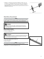
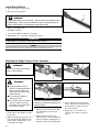
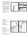
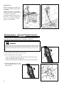
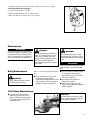
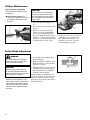
SHINDAIWA OWNER’S/OPERATOR’S MANUAL ARTICULATED HEDGE TRIMMER ATTACHMENT 78700 For Models: AH231, AH242, AHS231, AHS242, PB230, T230, T231, T242, T2510 Minimize the risk of injury to yourself and others! Read this manual and familiarize yourself with the contents. Always wear eye and hearing protection WARNING! when operating this unit. X7502890003 02/13 Introduction The Shindaiwa Articulated Hedge Trimmer Attachment is designed and built to deliver superior performance and reliability without compromise to quality, comfort, safety or durability. As an owner/operator, you'll soon discover for yourself why Shindaiwa is simply in a class by itself! Contents While every attempt has been made to provide the latest information about your Shindaiwa product, there may be some differences between your attachment and what is described here. IMPORTANT! The information contained in these instructions describes components available at the time of publication. ECHO, Inc. reserves the right to make changes to products without prior notice, and without obligation to make alterations to units previously manufactured. PAGE PAGE PAGE Introduction............................................. 2 Product Description................................ 5 Maintenance.......................................... 15 Attention Statements.............................. 2 Specifications........................................... 5 Troubleshooting Guide........................ 17 Safety........................................................ 2 Assembly................................................ ..6 Warranty Statement.............................. 18 IMPORTANT! The operational procedures described in this manual are intended to help you get the most from this unit as well as to protect you and others from harm. These procedures are guidelines for safe operation under most conditions, and are not intended to replace any safety rules and/or laws that may be in force in your area. If you have questions regarding your Shindaiwa hand held power equipment, or if you do not understand something in this manual, contact your local Shindaiwa dealer for assistance. You may also contact Shindaiwa at the address printed on the back of this Manual. Attention Statements Throughout this manual are special “attention statements”. DANGER! A statement preceded by the triangular attention symbol and the word “DANGER” contains information that should be acted upon to prevent serious injury or death. WARNING! A statement preceded by the triangular attention symbol and the word “WARNING” contains information that should be acted upon to prevent serious bodily injury. IMPORTANT! IMPORTANT! A statement preceded by the word “IMPORTANT” is one that possesses IMPORTANT! special significance. CAUTION! A statement preceded by the word IMPORTANT! “CAUTION” contains information IMPORTANT! that should be acted upon to prevent mechanical damage. NOTE: A statement preceded by the word “NOTE” contains information that is handy to know and may make your job easier. International Symbols Read and follow this manual, make sure anyone using the trimmer does likewise. Failure to do so could result in serious personal injury or machine failure. Keep this manual for future reference. Always wear a hard hat to reduce the risk of head injuries during operation of this machine. In addition, always wear eye and hearing protection. Shindaiwa recommends wearing a face shield as additional face and eye protection. Wear heavy duty, non-slip gloves. 2 Never operate this tool or any other power equipment if you are tired, ill, or under the influence of alcohol, drugs, or any substance that could affect your ability or judgement. This product conducts electricity. Keep the product and/or operator a minimum distance of 15 feet (4.5 meters) away from electrical sources and power lines. Keep bystanders at least 50 feet (15 meters) away from the operating trimmer to reduce the risk of being struck by falling objects or thrown debris. Be aware of the danger of falling debris. Safety This machine operates at very high speeds and has the potential to do serious damage if misused, abused or mishandled. To reduce the risk of injury, you must maintain control at all times, and observe all safety precautions during operation. Never permit a person without training or instruction to operate this machine! NOTE: For specific maintenance and safety information about your T230/231 or PB230, consult the owner's manual provided with it. If it has been lost or misplaced, contact a Shindaiwa dealer for a replacement. WARNING! THE PRUNER IS NOT INSULATED AGAINST ELECTRICAL SHOCK! Approaching or contacting electrical line with the pruner could cause death or serious injury. Keep the pruner at least 33 feet (10 meters) away from electrical lines or branches that contact electrical lines. CAUTION! Always maintain the Articulating Hedge Trimmer according to this owner’s manual and follow the recommended scheduled maintenance. Never modify or disable any of the hedge trimmer safety devices. Always use genuine Shindaiwa parts and accessories when repairing or maintaining this machine. When transporting the hedge trimmer in a vehicle, tie it down securely to prevent fuel spillage or damage to the machine. Always clear your work area of trash or hidden debris to help ensure good footing. Keep the cutters sharp and properly adjusted. Keep the hedge trimmer as clean as possible. Keep it free of loose vegetation, mud, debris, etc. WARNING! Hedge Clipper blades are very sharp. Touching them may lead to severe personal injury. Avoid touching blades whenever possible, and always wear gloves to protect hands Operating Precautions WARNING! This Shindaiwa Articulating Hedge Trimmer attachment is specifically designed for use on the Shindaiwa T230/231 grass trimmers, or PB230 power broom. Installation and/or use on any other model, brand or type of power tool is not approved by Shindaiwa. Attempts to use on non-approved models can damage the equipment and cause accidents, serious injury or death. Always make sure the cutting attachment is properly installed and firmly tightened before operation. If a cutter should bind fast in a cut, shut off the engine immediately. Push the branch or tree to ease the bind and free the cutter. Before starting the engine, make sure the cutter is not contacting anything. When cutting a branch that is under tension, be alert for springback so that you will not be struck by the moving branch. Always stop the engine immediately and check for damage if you strike a foreign object or if the machine becomes tangled. Do not operate with broken or damaged equipment. Stop the machine immediately if it suddenly begins to vibrate or shake. Inspect for broken, missing or improperly installed parts or attachments. Never transport the articulated hedge trimmer or leave it unattended with the engine running. An engine that’s running could be accidently accelerated causing the blades to oscillate. Make sure the blade cover is in place when transporting the articulated hedge trimmer. Do not make unauthorized modifications to the articulated hedge trimmer or its components. ■■Make sure the cutters are correctly adjusted before operating the articulated hedge trimmer (see “Cutter Blade Adjustment” for cutter adjustment procedures). Never attempt cutter adjustments with the engine running! ALWAYS keep a Solid Stance. Maintain footing and balance at all times. Do not stand on slippery, uneven or unstable surfaces. Do not work in odd positions or on ladders. Do not over reach. 3 Operating the Multipurpose Articulated Hedge Trimmer Tool WARNING! To avoid the chance of serious injury or death, follow these safety precautions during operation: This machine is designed for trimming hedges. Do not use this machine for other purposes. Keep bystanders at least 50 feet (15 meters) away from the operating trimmer to reduce the risk of being cut by the moving blades or struck by falling objects or thrown debris. NEVER allow children to use the unit. Avoid operating near bystanders or when children are nearby. Always wear a hard hat to reduce the risk of head injuries during operation of this machine. Always wear eye and hearing protection. Shindaiwa recommends wearing a face shield as additional face and eye protection. ALWAYS protect yourself from hazards such as thorny brush and flying debris by wearing gloves and close fitting clothing that covers arms and legs. Never wear shorts. Don't wear loose clothing or items such as jewelry that could get caught in machinery or underbrush. Secure long hair so it is above shoulder level. Always operate with both hands firmly gripping the machine. Keep a proper footing and do not overreach—maintain your balance at all times during operation. ALWAYS clear your work area of trash or hidden debris that could be thrown back at you or toward a bystander. IMPORTANT! Wear appropriate footwear (non-skid boots or shoes): do not wear open-toed shoes or sandals. Never work barefooted! ALWAYS be aware of your surroundings and alert to any danger that you may not hear due to machine noise. Safety Labels IMPORTANT! Safety and Information Labels: Make sure all safety and information labels are undamaged, readable and up to date. Immediately replace damaged or missing labels. This Attachment comes with safety labels shipped loose in the box. Attach these safety labels. New labels are available through your local authorized Shindaiwa dealer. 4 Product Description Using the illustration as a guide, familiarize yourself with your machine and its various components. Understanding your machine helps ensure top performance, long service life and safer operation. A - Adjustment lever A B - Gear case C - Cutter assembly C B WARNING! Do not make unauthorized modifications or alterations to your pole pruner or its components. Specifications Length mounted on T230 Dry Weight (Tool only) Blade Length Cutter drive 1829 mm (72.0 in) 1.8 kg (4.0 lbs) 567 mm (22.3 in.) Engranages Specifications are subject to change without notice. 5 Prior To Assembly Before assembling, make sure you have all the components required for a complete unit: Cutter assembly Cutter blade cover Heat-shrink Collar Throttle Grip w/interlock IMPORTANT! The terms “left”, “left-hand”, and “LH”; “right”, “right-hand”, and “RH”; “front” and “rear” refer to directions as viewed by the operator during normal operation. Hand protector w/screw & nut Owner's/Operator's manual Assembly Tool (s) Safety Labels Carefully inspect all components making sure they are not damaged. WARNING! Do not make unauthorized modifications or alterations to your pole pruner or its components. Assembly Installing The Interlock Throttle Grip Remove Outer Tube From Powerhead 6. Disconnect the red stop switch wire (B) by unplugging the bullet connector. 7. Use the 4 mm hex wrench to loosen the tube clamp screw (C). Loosen, but don't remove the screw, or the D-shaped shim washer (D) will fall out. 8. Pull the tube assembly out of the clamp. Set the powerhead aside. 1. Place the T230 or PB230 on a clean flat surface, in an upright position. 2. Remove the cylinder cover as instructed in your unit owner's manual. 3. Loosen the inner throttle cable adjusting nut with a 10 mm wrench. 4. Lift the throttle cable housing out of the notch on the powerhead. 5. Remove the throttle cable from the carburetor by lifting the Z-shaped cable end (A) out of the hole. B A A C 6 D Installing Throttle Grip B WARNING! ■ Failure to replace the standard throttle grip with the provided interlock throttle grip could permit unintentional acceleration, which could cause serious injuries or death. A 1. Place the T230 or PB230 outer tube assembly on a clean, flat surface. 2. Loosen the three screws (A) that hold the throttle trigger assembly to the outer tube. 3. Slide the trigger assembly down the tube, several inches away from the rubber grip. Rotate the trigger assembly so it is flat against the work surface. 2-in. C 4. With a utility knife or similar tool (B), slit the rubber grip lengthwise to release it from the tube. Use gentle pressure to avoid scarring the outer tube. WARNING! ■ To avoid serious injury, grip the outer tube securely with one hand and cut away from that hand when slitting the rubber throttle grip. 5. Remove the grip and slide the throttle trigger from the tube. Discard these parts. 6. Clean surface of tube in grip area. E F 7. Make a mark on the tube, 2 inches from the upper end. Slide the heat shrink collar (C) onto tube and align its upper end with the mark on the tube. 8. Using a heat gun or hair dryer, apply heat to the collar until it shrinks and forms a snug fit around the tube. D 9. Slide the new interlock throttle grip assembly (D) onto the tube, and position it over the collar. Make sure the switch is facing up, and that the throttle cable and switch wires (E) are positioned toward the powerhead. Using a cross-head screwdriver, tighten the grip's four clamp screws (F). Powerhead Reinstallation 1. Place the powerhead on a clean, flat surface in an upright position. CAUTION! J Do not remove the D-shaped shim washer! The shim washer prevents damage from overtightening the tube clamp screw. G 2. Slide the outer tube (G) into the tube clamp (H) until the outer tube bottoms. It should go in about 1-1/2 in. (38 mm). If the outer tube stops before bottoming, rotate it until you feel the inner driveshaft (I) splines engage the powerhead. Then push the outer tube all the way in. I CAUTION! Do not force the lower tube into the powerhead! Excessive force can damage the components. 3. Position the outer tube so the stop switch is facing up and the throttle cable/wire assembly (J) is on top. H 4. Use the hex wrench to tighten the clamp screw firmly. Make sure the D-shaped shim washer is in place. 7 Reconnecting the Throttle Cable, Switch Wires Connect The Throttle Cable. 1. Loop the ribbed cable assembly to the top left side of the engine. Confirm that the black ground wire (A) (with an eyelet on the end) is located between the two cable adjuster nuts (B). B D 2. Connect the Z-shaped end of the throttle cable (C) to the throttle lever on top of the carburetor. C 3. Turn the cable adjuster nuts sufficiently for the throttle cable to fit in the notch (D) on the fan cover. Make sure the ignition ground lead is located on the rearward side of the notch. Then, connect the male fitting of the red ignition wire into the female fitting of the red wire attached to the engine (E). A C E Adjusting the Throttle Cable 1. Loosen the two 10mm throttle cable nuts (B). 8 B 2. Adjust the throttle cable nuts until you achieve a free play on the throttle trigger of about 1/4 inch. IMPORTANT! Make sure the stop switch wires do not interfere with throttle functions. Reposition wires if necessary. 3. When 1/4-inch of free play is achieved, securely tighten the two 10mm throttle cable nuts. When the throttle cable is correctly adjusted, and the throttle trigger is fully depressed (full throttle), the throttle will contact the stop on the throttle body (F). 1/4” NOTE: Apply anti-seize oil on the cylinder cover knob threads for easier removal. 4. Replace the cylinder cover. 5. Replace the spark plug boot. Removing the Trimmer/PowerBroom Attachment 1. Place the re-gripped T230 or PB230 on a clean, flat surface in an upright position. For the T230/T231 Trimmers: 2. Loosen, but don't remove the gearcase clamp screw (A) and nut using a 4 mm hex wrench and an 8 mm open end wrench. 3. Use the 4 mm hex wrench to loosen the gearcase index screw (B) until it is almost free. 4. Use the 4 mm hex wrench to loosen the four debris shield attachment screws (C). Loosen them only enough to free the debris shield assembly from the outer tube. This will make it easier to reattach the debris shield when converting back to a trimmer. 5. Pull and rotate the debris shield, gearcase, and trimmer head assembly until it slides off the outer tube. F C B A NOTE: The gearcase and debris shield are connected by the clamp screw. 6. The debris shield has two shims (D) located on either side of the outer tube and the debris shield bracket. Put the shims and the debris shield/gearcase assembly in a safe place, so that they can be reinstalled later if desired. For the PB230 PowerBroom: 1. Using a 5 mm hex wrench and a 10 mm open end wrench, loosen, but don't remove, the gearcase clamp screw. 2. Using the 4 mm hex wrench, back out the index screw until it is almost free. 3. Pull and rotate the gearcase/sweeper drum assembly until it slides off the outer tube. 4. Remove the spacer from the outer tube if it did not slide off with gearcase/ sweeper drum assembly. Put the spacer and gearcase/sweeper drum assembly in a safe place, so they can be reinstalled later if desired. 5. If your PB230 is equipped with the optional guard assembly, it must be removed. Use 4 mm hex wrench to remove its four clamp screws. Slide the protective collar off the outer tube. D NOTE: For help reinstalling the original gearcase and attachments, consult the owner's manual that came with your T230, T231, or PB230. 9 Installing the Hand Protector A 1. Measure 24-1/2 in. (622 mm) from the bottom end of the outer tube and make a mark on the tube. C 2. Slide the hand protector/cutter rest (A) up the outer tube, making sure its protruding collar (B) faces toward the end of the tube and its clamp slot faces down. B 3. Position the hand protector/cutter rest so the front of the protruding collar aligns with the mark on the outer tube. 4. When positioned properly, the end of the cutter bar will fit into the notch (C) on the hand protector. 5. When the proper location is set, tighten the clamp screw with a screwdriver. WARNING! ■ The provided labels offer important safety information about hedge trimmers. Do not operate, or allow others to operate, this machine unless the labels are properly installed. Installing the Caution Labels 1. Clean outer tube so the labels will adhere properly. 2. Peel the backing off the multiple warning label and attach below similar label on lower part of outer tube. Make sure label faces up and that it is legible from the operator's position. 3. Peel the backing off "The Electrical Shock Danger" label and attach it just ahead of the throttle grip. Make sure the label faces up and that it is legible from the operator's position. Installing the Hedge Trimmer Cutter Assembly 1. Make sure the cutter bar is locked in the storage/transport position (folded back) and the protective cover is installed over the cutter blades (F). F 2. Remove index screw (D). D 3. Insert the end of the outer tube into the gear case clamp assembly and push until it bottoms. The outer tube should go into the gear case about 1-1/2 in. (38 mm). If the outer tube stops before bottoming, rotate it until you feel the inner main shaft (drive shaft) splines engage the gear case. Then push the outer tube all the way in. 4. Rotate the gear case/cutter assembly so that index screw hole aligns with the hole in the outer tube. With the power head in the upright position, the cutter assembly will appear to be upside down (while in the storage/transport position). 5. Install and tighten the index screw first, then tighten the gear case clamp screw (E). 6. Adjust the hand protector/cutter rest so that the tip of the cutter bar fits into the support notch (C). Make sure the cutter bar also lifts out of the notch easily. Then tighten the hand protector clamp screw with screwdriver. 10 E C 7. Shindaiwa recommends leaving the T230 or PB230 loop handle on the outer tube. However, for maximum comfort and control, it may require adjustment. Use the 4mm Allen wrench to loosen the handle’s four clamp screw. Move the handle along the tube to a point where the best comfort an control are observed. Retighten the clamp screws. Blade Stiffener Removal/Install NOTE: For normal cutting, Shindaiwa strongly recommends the blade stiffener be installed. In extreme conditions, such as commercial cutting, or when cutting thick and/or dense branches, efficiency may be increased by trimming without the blade stiffener. WARNING! Hedge Clipper blades are very sharp. Touching them may lead to severe personal injury. Avoid touching blades whenever possible, and always wear gloves to protect hands. Blade Stiffener Removal 1. Move stop switch to stop position. 2. Disconnect spark plug wire. WARNING! Hedge clipper blades are very sharp. Touching them may lead to severe personal injury. Use a socket and extension when removing locknuts in order to keep hands at a safe distance from sharp blades. 3. Remove four (4) blade stiffener locknuts (A). A 4. Remove blade stiffener. 5. Install (4) locknuts. NOTE: Use new locknuts every other time blade stiffener is installed or removed. 6. Adjust blades. See “Cutter blade adjustment” section. 11 Install Blade Stiffener 1. Move stop switch to stop position. 2. Disconnect spark plug wire. B WARNING! Hedge clipper blades are very sharp. Touching them may lead to severe personal injury. Use a socket and extension when removing locknuts in order to keep hands at a safe distance from sharp blades. 3. Remove (4) locknuts (B). 4. Install blade stiffener. 5. Secure blade stiffener with four (4) locknuts. 6. Adjust blades. See “Cutter blade adjustment” section. IMPORTANT! If blade stiffener is damaged or show signs of wear, replace it. NOTE: Use new locknuts every other time blade stiffener is installed or removed. Adjusting the Hedge Trimmer Cutter Assembly B WARNING! Never run the engine when adjusting the cutter assembly. A WARNING! B A ■■The cutter blades are very sharp. Do not grasp the blades with your hands. Always use gloves when working near the cutter assembly. ■■Do not allow the blades to contact your body. ■■Do not touch the cutter blades when the engine is running. The blades can oscillate even if the engine is idling. 1. Position the hedge trimmer on a flat, level surface. 2. With your right hand, grasp the outer tube near the handle. With your left hand, grip the adjustment lever (A) on the cutter assembly. 12 C IMPORTANT! The latch lock provides an interlock to help prevent inadvertent depression of the latch release. 3. With the index finger of your left hand, press the latch lock (B). With your left thumb, press the latch release (C). 4. While holding the latch release down, pivot the cutter assembly away from you using the adjustment lever until it is at the desired cutting angle. 5. Release the latch lock and the latch release. Make sure the latch lock and the latch release return securely to the locked position. 6. Remove the cover from the cutter blade. The engine now may be started. Cutter Assembly Positions The cutter assembly can be adjusted to eleven different positions ranging from 120° to 270° from the outer tube as shown. Always make sure the latch lock is securely locked after each adjustment. 270° 120° Various blade positions possible Adjusting for Storage or Transportation 1. With the engine off, install the blade cover onto the blade. 2. Using the procedures described above, rotate the cutter assembly so it is parallel to the tube. Make sure the latch lock and the latch release return securely to a locking position. Gearcase rotated to the storage/ transportation position Adjusting for Storage or Transportation WARNING! Cutter Assembly Positions Never run the engine when adjusting the cutter assembly. 3. Make sure the blade cover is in place on the cutters before storing or transporting. Operation Using the Hedge Trimmer Preparations Use lopping shears to cut out thick branches first. Cutting Sequence If a radial cut is necessary, cut a little at a time in several passes. Cutting Techniques Vertical Cut: Swing the blade up and down in an arc as you move along the hedge. Use both sides of the cutting blade. Cut without standing directly next to the hedge, e.g. with a flower bed between operator and hedge. Vertical Cut Overhead Cut Overhead Cut: Hold the shaft upright with a 90° blade angle to cut an upper surface of a hedge. 13 Horizontal Cut: Hold the cutting blade at an angle of 0° to 10° as you swing the hedge trimmer horizontally. Swing the blade in an arc towards the outside of the hedge so that the cuttings are swept on to the ground. Cut without standing directly in front of the hedge, e.g. reach over a flower bed. Cut close to the ground from a standing position, e.g., for low shrubs. Horizontal Cut Horizontal Cut at ground level Starting Engine – Interlock Throttle Controls IMPORTANT! The engine ignition is controlled by a two-position ON-OFF switch mounted on the throttle grip assembly, typically labelled “I” for START and “O” for STOP. WARNING! The attachment will operate immediately when the engine starts, and could result in possible serious injury. Keep movable parts of the attachment away from objects that could become entangled or thrown, and surfaces that could cause loss of control. C Control Positions (cold engine) 1. Slide the ignition switch (A) to the “ON” position. B 2. Set the throttle trigger to the “fast idle”: a.Depress and hold the throttle lock (B), then squeeze the throttle trigger. b.Depress and hold the fast idle button (C). A c.Release the throttle trigger and throttle lock, then release fast idle button. 3. Press the purge bulb (D) four or five times. You should be able to see fuel inside the bulb. D 14 4. Choke the engine by moving the choke lever (E) up to the “closed” position. E Control Positions (warm engine) 1. Set the throttle trigger to “fast idle” 2. Slide the ignition switch to the “I” (ON) position. 3. Move the choke lever down to the “open” position. P23007 Maintenance IMPORTANT! For detailed maintenance information about your T230/231, or PB230, consult the owner's manual that was provided with it. If it has been lost or misplaced, contact Shindaiwa for a replacement. Daily Maintenance WARNING! Always wear gloves when working around the cutter assembly. WARNING! Before performing any maintenance, repair, or cleaning work on the unit, make sure the engine and cutting attachment are completely stopped. Disconnect the spark plug wire before performing service or maintenance work. Prior to each work day, perform the following: ■■Clean any debris or dirt from the hedge trimmer cutter blades. Lubricate the blades before use and after refueling. Check the cutters for damage or incorrect adjustment. WARNING! Non-standard parts may not operate properly with your unit and may cause damage and lead to personal injury. IMPORTANT! Using non-standard replacement parts could invalidate your Shindaiwa warranty. ■■Check for loose or missing screws or components. Make sure the cutter attachment is free of debris and securely fastened. ■■Check the entire machine for leaking fuel or grease. ■■Make sure the nuts, bolts, and screws (except carburetor adjusting screws) are tight. 10/15-Hour Maintenance ■■Lubricate the cutter assembly gearbox by pumping one or two strokes of lithium-base grease into the grease fitting (A) using a levertype grease gun. CAUTION! A Overlubricating can cause the gearcase to operate sluggishly and can cause grease to leak out. 15 50-Hour Maintenance Every 50 hours of operation (more frequently in dusty or dirty conditions): ■■Lubricate the gearcase. To perform this operation, first remove the gearcase (A) from the outer tube (B). A Do not remove the D-shaped shim washer from the gearcase clamp! The shim washer prevents damage from overtightening the gearcase clamp screw. 1. Loosen the gearcase clamp screw (C). 2. Remove the index screw (D) from the gearcase. C B CAUTION! D E 3. Slide the gearcase out of the tube. Using a grease gun, pump lithiumbase grease (about 10 grams) into the grease fitting (E) on the gearcase 4. Clean up the excess grease, then reassemble the gearcase onto the outer until you see old grease being purged tube. Make sure the index screw from the gearcase. Purged grease will fits into the hole on the outer tube. be visible in the outer tube cavity. Securely tighten both screws. Cutter Blade Adjustment WARNING! The cutter blades are very sharp! Always wear gloves when working around the cutter assembly. CAUTION! Operating the trimmer with worn or improperly adjusted cutters will reduce cutter performance and may also damage your machine. Cutter performance of your machine depends in great measure on the cutter blade clearance. Properly adjusted blades will oscillate freely yet help prevent binding of cut material between blades. Adjust the blades as follows: 16 A 1. Loosen all the blade locknuts (A) at least one full turn. 2. Tighten each blade shoulder bolt (B) firmly, and then loosen the shoulder bolts 1/4 to 1/2 turn. 3. Working from the gearcase end, lock each bolt in place by firmly tightening its locknut while preventing the shoulder bolt from turning. When shoulder bolt adjustment is correct, there should be a gap of 0.25–0.50 mm between the cutter blades and the flat washers (C) beneath each bolt head should turn freely. B C Troubleshooting Guide Symptom Excessive vibration. Cutting attachment will not move. Cutting attachment moves at engine idle. ADDITIONAL PROBLEMS Possible Cause Remedy Warped or damaged attachment. Inspect and replace attachment as required. Loose gearcase. Tighten gearcase securely. Bent main shaft/worn or damaged bushings. Inspect and replace as necessary. Shaft not installed in powerhead or gearcase. Inspect and reinstall as required. Broken shaft. Consult with an authorized Shindaiwa servicing dealer. Damaged gearcase. Engine idle too high. Adjust idle. Check Specifications page for correct idle speed. Broken clutch spring or worn clutch spring boss. Replace spring/shoes as required, check idle speed. 17 SHINDAIWA LIMITED WARRANTY STATEMENT FOR PRODUCT SOLD IN USA AND CANADA BEGINNING 01/01/2013 ECHO, INC’S RESPONSIBILITY ECHO Incorporated’s (ECHO, INC.) Limited Warranty, provides to the original purchaser that this Shindaiwa product is free from defects in material and workmanship. Under normal use and maintenance from date of purchase, ECHO, INC. agrees to repair or replace at it’s discretion, any defective product free of charge at any authorized Shindaiwa servicing dealer within listed below application time periods, limitations and exclusions. THIS LIMITED WARRANTY IS ONLY APPLICABLE TO SHINDAIWA PRODUCTS SOLD BY AUTHORIZED SHINDAIWA DEALERS. IT IS EXTENDED TO THE ORIGINAL PURCHASER ONLY, AND IS NOT TRANSFERABLE TO SUBSEQUENT OWNERS EXCEPT FOR EMISSION RELATED PARTS. Repair parts and accessories replaced under this warranty are warranted only for the balance of the original unit or accessory warranty period. Any damage caused by improper installation or improper maintenance is not covered by this warranty. All parts or products replaced under warranty become the property of ECHO, INC. This warranty is separate from the Emission control warranty statement supplied with your new product. Please consult the Emission Control Warranty Statement for details regarding emission related parts. For a list of Authorized Shindaiwa Dealers refer to WWW.SHINDAIWA.COM or call 1-877-986-7783. OWNER’S RESPONSIBILITY To ensure trouble free warranty coverage it is important that you register your Shindaiwa equipment on-line at WWW.SHINDAIWA. COM or by filling out the warranty registration card supplied with your unit. Registering your product confirms your warranty coverage and provides a direct link if we find it necessary to contact you. The owner shall demonstrate reasonable care and use, and follow preventative maintenance, storage, fuel and oil usage as prescribed in the operator’s manual. Should a product difficulty occur, you must, at your expense, deliver or ship your Shindaiwa unit to an authorized Shindaiwa servicing dealer for warranty repairs (within the applicable warranty period), and arrange for pick-up or return of your unit after the repairs have been made. For your nearest authorized Shindaiwa servicing dealer, call Shindaiwa’s Dealer Referral Center, at 1-877-986-7783 or you can locate a Shindaiwa servicing dealer at WWW.SHINDAIWA.COM. Should you require assistance or have questions concerning Shindaiwa’s Warranty Statement, you can contact our Consumer Product Support Department at 1-800-673-1558 or contact us through the web at WWW.SHINDAIWA.COM. PRODUCT WARRANTY PERIOD RESIDENTIAL APPLICATION • 5 YEAR WARRANTY - Units for residential, or non-income producing use will be covered by this limited warranty for five (5) years from date of purchase. EXCEPTIONS: • For engine powered products, the electronic ignition module, flexible drive cable, and solid drive shaft are warranted for the life* of the product on parts only. • Cutting attachments such as, but not limited to, bars, chains, sprockets, tines, blades, PowerBroomTM, belts, and nylon trimmer heads for residential or non-income producing use will be covered for failures due to defects in material or workmanship for a period of 60 days from original product purchase date. Any misuse from contact with concrete, rocks, or other structures is not covered by this warranty. • Multipurpose Tool Attachments carry the same warranty duration as the units they are designed to fit. COMMERCIAL APPLICATION • 90 DAY WARRANTY - All Chain Saws and Cut-Off Saws for commercial, institutional, agricultural, industrial, or income producing use will be covered by this limited warranty for 90 Days from the date of purchase. • 2 YEAR WARRANTY - All other units for commercial, institutional, agricultural, industrial, or income producing use will be covered by this limited warranty for two (2) years from the date of purchase. EXCEPTIONS: • For engine powered products, the electronic ignition module, flexible drive cables, and solid drive shafts are warranted for the life* of the product on parts only. • Cutting attachments such as, but not limited to, bars, chains, sprockets, tines, blades, PowerBroomTM, belts, and nylon trimmer heads for commercial, institutional, agricultural, industrial, rental, or income producing will be covered for failures due to defects in material or workmanship for a period of 30 days from original product purchase date. Any misuse from contact with concrete, rocks, or other structures is not covered by this warranty. • Multipurpose Tool Attachments carry the same warranty duration as the units they are designed to fit. RENTAL APPLICATION - 90 DAYS WARRANTY • Units for rental use will be covered against defects in material and workmanship for a period of 90 days from the date of purchase. * 18 ECHO INC’s liability under the “Lifetime” coverage is limited to furnishing parts specified under the PRODUCT Warranty PERIOD section of this warranty statement for “Life” free of charge for a period of ten (10) years after the date of the complete unit’s final production. PURCHASED REPAIR PARTS AND ACCESSORIES • 90-day all applications ATTENTION ENGINE POWERED PRODUCT OWNERS This Shindaiwa engine powered product is a quality-engineered unit which has been manufactured to exact tolerances to provide superior performance. To help ensure the performance of the unit, it is required to use engine oil which meets the ISO-L-EGD Standard per ISO/CD 13738 and JASO M345/FD Standards. Shindaiwa Red ArmorTM and Shindaiwa OneTM are a premium engine oil specifically formulated to meet ISO-L-EGD (ISO/CD 13738) and JASO M345/FD Standards. The use of engine oils designed for other applications, such as for outboard motors or lawnmowers can result in severe engine damage, and will void your engine limited warranty. THIS WARRANTY DOES NOT COVER DAMAGE CAUSED BY: • Lack of lubrication or engine failure, due to the use of engine oils that do not meet the ISO-L-EGD (ISO/CD 13738) and JASO M345/FD Standards. Shindaiwa Red ArmorTM and Shindaiwa OneTM Engine Oil meets the ISO-L-EGD and JASO M345/FD Standard. Emission related parts are covered for 5 years residential or 2 years commercial use regardless of two-stroke oil used, per the statement listed in the EPA or California Emission Control Warranty Explanation. • Damage caused by use of gasohol, containing methanol (wood alcohol), or gasoline containing less than 89 octane. Only use gasoline which contains 89 octane or higher. Gasohol which contains a maximum 10% ethanol (grain alcohol) or 15% MTBE (methyl/tertiary/butyl/ether) is also approved. The prescribed mixing ratio of gasoline to oil is listed on the Shindaiwa oil label and covered in your operator’s manual. • Engine damage caused by use of ether or any starting fluids. • Damage caused by tampering with engine speed governor or emission components, or running engines above specified and recommended engine speeds as listed in your operator’s manual. • Operation of the unit with improperly maintained/removed cutting shield or removed/damaged air filter. • Damage caused by dirt, pressure or steam cleaning the unit, salt water, corrosion, rust, varnish, abrasives, and moisture. • Defects, malfunctions or failures resulting from abuse, misuse, neglect, modifications, alterations, normal wear, improper servicing, or use of unauthorized attachments. • Incorrect storage procedures, stale fuel, including failure to provide or perform required maintenance services as prescribed in the operator’s manual. Preventative maintenance as outlined in the operator’s manual is the customer’s responsibility. • Failures due to improper set-up, pre-delivery service or repair service by anyone other than authorized Shindaiwa servicing dealer during the warranty period. • Certain parts and other items are not warranted, including but not limited to: lubricants, starter cords, and engine tune-ups. • Use of spark plugs other than those meeting performance and durability requirements of the OEM spark plug listed in the Operator’s Manuals. • Overheating or carbon scoring failures due to restricted, clogged exhaust port or combustion chamber, including damage to spark arrester screen. • Adjustments after the first (30) thirty days and beyond, such as carburetor adjustment and throttle cable adjustment. • Damage to gears or gear cases caused by contaminated grease or oil, use of incorrect type or viscosity of lubricants, and/or failure to comply with recommended grease or oil change intervals. • Damage caused by pump or sprayer running dry, pumping or spraying caustic or flammable materials, or lack of or broken strainers. • Additional damage to parts or components due to continued use after operational problem or failure occurs. Should operational problem or failure occur, the product should not be used, but delivered as is to an authorized Shindaiwa servicing dealer. It is a dealer’s and/or customer’s responsibility to complete and return the warranty registration card supplied with your Shindaiwa product or by visiting WWW.SHINDAIWA.COM. Your receipt of purchase including date, model and serial number must be maintained and presented to an authorized Shindaiwa servicing dealer for warranty service. Proof of purchase rests solely with the customer. Some states do not allow limitations on how long an implied warranty lasts, so the above limitations may not apply to you. Some states do not allow the exclusion or limitation of incidental or consequential damages, so you may also have other specific legal rights which vary from state to state. This limited warranty is given by ECHO Incorporated, 400 Oakwood Rd., Lake Zurich, IL 60047. DISCLAIMER OF IMPLIED WARRANTIES This limited warranty is in lieu of all other expressed or implied warranties, including any warranty of FITNESS FOR A PARTICULAR PURPOSE OR USE and any implied warranty of MERCHANTABILITY otherwise applicable to this product. ECHO, INC. and its affiliated companies shall not be liable for any special incidental or consequential damage, including lost profits. There are no warranties extended other than as provided herein. This limited warranty may be modified only by ECHO, INC. X7561120400 01/13 19 Servicing Information Parts/Serial Number Genuine Shindaiwa Parts and Assemblies for your Shindaiwa products are available only from an Authorized Shindaiwa Dealer. When you do need to buy parts always have the Model Number, Type and Serial Number of the unit with you. You can find these numbers on the engine. For future reference, write them in the space provided below. Model No. _____________ SN. ______________ Service Service of this product during the warranty period must be performed by an Authorized Shindaiwa Service Dealer. For the name and address of the Authorized Shindaiwa Service Dealer nearest you, ask your retailer or call: 1-877986-7783. Dealer information is also available on WWW.SHINDAIWA.COM. When presenting your unit for Warranty service/repairs, proof of purchase is required. Consumer Product Support If you require assistance or have questions concerning the application, operation or maintenance of this product you may call the Shindaiwa Consumer Product Support Department at 1-877-986-7783 from 8:30 am to 4:30 pm (Central Standard Time) Monday through Friday. Before calling, please know the model and serial number of your unit. Warranty Registration To ensure trouble free warranty coverage it is important that you register your Shindaiwa equipment by filling out the warranty registration card supplied with your unit. Registering your product confirms your warranty coverage and provides a direct link if we find it necessary to contact you. Additional or Replacement Manuals Replacement Operator and Parts Catalogs are available from your Shindaiwa dealer or at WWW.SHINDAIWA.COM or by contacting the Consumer Product Support Department (1-877-986-7783). Always check WWW.SHINDAIWA. COM for updated information. ECHO Incorporated. 400 Oakwood Road Yamabiko Corporation Lake Zurich, IL 60047-1564 U.S.A. 7-2 Suehirocho 1-Chome, Ohme, Tokyo, 198-8760, Japan Telephone: 1-877-986-7783 Fax: 1-847-540-8416 Phone: 81-428-32-6118 www.shindaiwa.com Fax: 81-428-32-6145 Copyright© 2013 By Echo, Incorporated All Rights Reserved. T19400001001/T19400999999