1
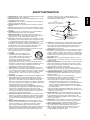
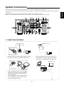
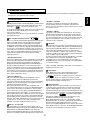
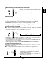
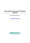
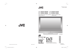
R-865
Audio/Video Receiver
Introduction
ENGLISH
READ THIS BEFORE OPERATING YOUR UNIT
This symbol is intended to alert the user to the
presence of uninsulated "dangerous voltage"
within the product's enclosure that may be of
sufficient magnitude to constitute a risk of
electric shock to persons.
CAUTION
WARNING
: TO REDUCE THE RISK OF
ELECTRIC SHOCK, DO NOT
REMOVE COVER (OR BACK). NO
USER-SERVICEABLE PARTS
INSIDE. REFER SERVICING TO
QUALIFIED SERVICE PERSONNEL.
This symbol is intended to alert the user to the
presence of important operating and
maintenance (servicing) instructions in the
literature accompanying the appliance.
: TO REDUCE THE RISK OF FIRE OR ELECTRIC SHOCK,
DO NOT EXPOSE THIS APPLIANCE TO RAIN OR MOISTURE.
Note to CATV System Installer :
This reminder is provided to call the CATV system installer’s attention to Article 820-40 of the NEC that provides
guidelines for proper grounding and, in particular, specifies that the cable ground shall be connected to the
grounding system of the building, as close to the point of cable entry as pracitcal.
FCC INFORMATION
This equipment has been tested and found to comply with the limits for a Class B digital device, pursuant to Part 15 of
the FCC Rules. These limits are designed to provide reasonable protection against harmful interference in a residential
installation. This equipment generates, uses and can radiate radio frequency energy and, if not installed and used in
accordance with the instructions, may cause harmful interference to radio communications. However, there is no
guarantee that interference will not occur in a particular installation. If this equipment does cause harmful interference to
radio or television reception, which can be determined by turning the equipment off and on, the user is encouraged to
try to correct the interference by one or more of the following measures:
• Reorient or relocate the receiving antenna.
• Increase the separation between the equipment and receiver.
• Connect the equipment into an outlet on a circuit different from that to which the receiver is connected.
• Consult the dealer or an experienced radio/TV technician for help.
Caution : Any changes or modifications in construction of this device which are not expressly approved by the party
responsible for compliance could void the user’s authority to operate the equipment.
FOR YOUR SAFETY
Units shipped to the U.S.A and Canada are designed for operation on 120 V AC only.
Safety precaution with use of a polarized AC plug.
However, some products may be supplied with a nonpolarized plug.
U.S.A
CANADA
120 V
CAUTION
: To prevent electric shock, match wide blade of plug to wide slot, fully
insert.
ATTENTION
•
•
•
•
•
•
•
•
: Pour éviter chocs électriques, introduire la lame la plus large de la
fiche dans la borne correspondante de la prise et pousser jusqu’ au
fond.
Avoid high temperatures. Allow for sufficient heat dispersion when installed on a rack.
Keep the set free from moisture, water, and dust.
Do not let foreign objects in the set.
Handle the power cord carefully. Hold the plug when unplugging the cord.
Unplug the power cord when not using the set for long periods of time.
Do not obstruct the ventilation holes.
Do not let insecticides, benzene, and thinner come in contact with the set.
Never disassemble or modify the set in any way.
2
1. Read Instructions - All the safety and operating instructions should
be read before the product is operated.
2. Retain instructions - The safety and operating instructions should
be retained for future reference.
3. Heed Warnings - All warnings on the product and in the operating
instructions should be adhered to.
4. Follow Instructions - All operating and use instructions should be
followed.
5. Cleaning - Unplug this product from the wall outlet before cleaning.
Do not use liquid cleaners or aerosol cleaners. Use a damp cloth for
cleaning.
6. Attachments - Do not use attachments not recommended by the
product manufacturer as they may cause hazards.
7. Water and Moisture - Do not use this product near water - for
example, near a bath tub, wash bowl, kitchen sink, or laundry tub; in
a wet basement, or near a swimming pool; and the like.
8. Accessories - Do not place this product on an unstable cart, stand,
tripod, bracket, or table. The product may fall, causing serious injury
to a child or adult, and serious damage to the product. Use only with
a cart, stand, tripod, bracket, or table recommended by the
manufacturer, or sold with the product. Any mounting of the product
should follow the manufacturer’s instructions, and should use a
mounting accessory recommended by the manufacturer.
9. A product and cart combination should be moved with care. Quick
stops, excessive force, and uneven surfaces
may cause the product and cart combination
to overturn.
10. Ventilation - Slots and openings in the
cabinet are provided for ventilation and to
ensure reliable operation of the product and
to protect it from overheating, and these
openings must not be blocked or covered.
PORTABLE CART WARNING
The openings should never be blocked by
placing the product on a bed, sofa, rug, or other similar surface.
This product should not be placed in a built-in installation such as a
bookcase or rack unless proper ventilation is provided or the
manufacturer’s instructions have been adhered to.
11. Power Sources - This product should be operated only from the
type of power source indicated on the marking label. If you are not
sure of the type of power supply to your home, consult your product
dealer or local power company. For products intended to operate
from battery power, or other sources, refer to the operating
instructions.
12. Grounding or Polarization - This product may be equipped with a
polarized alternating-current line plug (a plug having one blade
wider than the other). This plug will fit into the power outlet only one
way. This is a safety feature. If you are unable to insert the plug
fully into the outlet, try reversing the plug. If the plug should still fail
to fit, contact your electrician to replace your obsolete outlet. Do not
defeat the safety purpose of the polarized plug.
Alternate Warnings - This product is equipped with a three-wire
grounding-type plug, a plug having a third(grounding) pin. This plug
will only fit into a grounding-type power outlet. this is a safety
feature. If you are unable to insert the plug into the outlet, contact
your electrician to replace your obsolete outlet. Do not defeat the
safety purpose of the grounding-type plug.
13. Power-Cord Protection - Power-supply cords should be routed so
that they are not likely to be walked on or pinched by items placed
upon or against them, paying particular attention to cords at plugs,
convenience receptacles, and the point where they exit from the
product.
14. Outdoor Antenna Grounding - If an outside antenna or cable
system is connected to the product, be sure the antenna or cable
system is grounded so as to provide some protection against
voltage surges and built-up static charges. Article 810 of the
National Electrical Code, ANSI/NFPA 70, provides information with
regard to proper grounding of the mast and supporting structure,
grounding of the lead-in wire to an antenna discharge unit, size of
grounding conductors, location of antenna-discharge unit,
connection to grounding electrodes, and requirements for the
grounding electrode. See Figure 1.
Figure 1
Example of antenna grounding as per
National Electrical Code, ANSI/NFPA 70
ANTENNA
LEAD IN
WIRE
GROUND
CLAMP
ANTENNA
DISCHARGE UNIT
(NEC SECTION 810-20)
ELECTRIC
SERVICE
EQUIPMENT
GROUNDING CONDUCTORS
(NEC SECTION 810-21)
GROUND CLAMPS
POWER SERVICE GROUNDING
ELECTRODE SYSTEM
(NEC ART 250, PART H)
NEC - NATIONAL ELECTRICAL CODE
15. Lightning - For added protection for this product during a lightning
storm, or when it is left unattended and unused for long periods of
time, unplug it from the wall outlet and disconnect the antenna or
cable system. This will prevent damage to the product due to
lightning and power-line surges.
16. Power Lines - An outside antenna system should not be located in
the vicinity of overhead power lines or other electric light or power
circuits, or where it can fall into such power lines or circuits. When
installing an outside antenna system, extreme care should be taken
to keep from touching such power lines or circuits as contact with
them might be fatal.
17. Overloading - Do not overload wall outlets, extension cords, or
integral convenience receptacles as this can result in a risk of fire
or electric shock.
18. Object and Liquid Entry - Never push objects of any kind into this
product through openings as they may touch dangerous voltage
points or short-out parts that could result in a fire or electric shock.
Never spill liquid of any kind on the product.
19. Servicing - Do not attempt to service this product yourself as
opening or removing covers may expose you to dangerous voltage
or other hazards. Refer all servicing to qualified service personnel.
20. Damage Requiring Service - Unplug this product form the wall
outlet and refer servicing to qualified service personnel under the
following conditions:
a) When the power-supply cord or plug is damaged,
b) If liquid has been spilled, or objects have fallen into the product,
c) If the product has been exposed to rain or water,
d) If the product does not operate normally by following the
operating instructions. Adjust only those controls that are
covered by the operating instructions as an improper adjustment
of other controls may result in damage and will often require
extensive work by a qualified technician to restore the product to
its normal operation.
e) If the product has been dropped or damaged in any way, and
f) When the product exhibits a distinct change in performance - this
indicates a need for service.
21. Replacement Parts - When replacement parts are required, be
sure the service technician has used replacement parts specified
by the manufacturer or have the same characteristics as the
original part. Unauthorized substitutions may result in fire, electric
shock, or other hazards.
22. Safety Check - Upon completion of any service or repairs to this
product, ask the service technician to perform safety checks to
determine that the product is in proper operating condition.
23. Wall or Ceiling Mounting - The product should be mounted to a
wall or ceiling only as recommended by the manufacturer.
24. Heat - The product should be situated away from heat sources
such as radiators, heat registers, stoves, or other products
(including amplifiers) that produce heat.
3
ENGLISH
SAFETY INSTRUCTION
ENGLISH
CONTENTS
• Introduction
READ THIS BEFORE OPERATING YOUR UNIT
SAFETY INSTRUCTION | 3
• System Connections
| 5
• Front Panel Controls
| 14
| 2
• Universal Remote Controls
| 16
OPERATING COMPONENTS WITH REMOTE CONTROL
REMOTE CONTROL OPERATION RANGE | 18
LOADING BATTERIES | 18
USING FUNCTIONS OF REMOTE CONTROL | 19
| 18
• ROOM 2 Remote Controls
REMOTE CONTROL OPERATION RANGE
LOADING BATTERIES | 27
| 27
• Operations
LISTENING TO A PROGRAM SOURCE | 28
SURROUND SOUND | 31
ENJOYING SURROUND SOUND | 34
LISTENING TO RADIO BROADCASTS | 39
RECORDING | 42
DIGITAL AUDIO RECORDING WITH MD RECORDER
OTHER FUNCTIONS | 44
ROOM 2 SOURCE PLAYBACK | 46
• Using OSD
CURRENT STATUS DISPLAY
| 47
• OSD Menu Settings
| 47
SETTING THE POWER AMP ASSIGN | 49
SETTING THE SPEAKER SETUP | 49
SETTING THE SYSTEM SETUP | 57
SETTING THE SURROUND SETUP | 63
SETTING THE CH LEVEL SETUP | 66
SETTING THE ROOM2 FEED SETUP | 69
• Troubleshooting Guide
• Specifications
| 71
| 72
• Setup Code Table
| 73
4
| 43
• Pleas be certain that this unit is unplugged from the AC outlet before making any connections.
• Since different components often have different terminal names, carefully read the operating instructions of the component
connected.
• Be sure to observe the color coding when connecting audio, video and speaker cords.
• Make connections firmly and correctly. If not, it can cause loss of sound, noise or damage to the unit.
3
12 7
1
14
8 10 11
MANUFACTURED UNDER LICENSE FROM DOLBY
LABORATORIES. "DOLBY", "PRO LOGIC", AND THE
DOUBLE-D SYMBOL ARE TRADEMARKS OF DLOBY
LABORATORIES.
9
9
SPEAKER IMPEDANCE
FRONT , CENTER , SURROUND A or B,
SURROUND BACK : 6 OHMS ( ) MIN.
SURROUND A and B : 12 OHMS( ) MIN.
6
5
4
2
3
5
13
1. CONNECTING ANTENNAS
FM Indoor Antenna
FM Outdoor Antenna
• A 75Ω outdoor FM antenna may be used to further improve the reception. Disconnect the indoor
antenna before replacing it with the outdoor one.
• Change the position of the FM indoor antenna until you
get the best reception of your favorite FM stations.
AM Outdoor Antenna
AM Loop Antenna
AM Loop Antenna
• Place the AM loop antenna as far as possible
from the receiver, TV set, speaker cords and
the AC input cord and set it to a direction for
the best reception.
• If the reception is poor with the AM loop antenna, an AM outdoor antenna can be used in
place of the AM loop antenna.
5
ENGLISH
System Connections
2. CONNECTING AUDIO COMPONENTS
ENGLISH
TAPE MONITOR Tape deck, MD recorder, etc.
AUX Additional tape deck. etc.
AUDIO L
IN
R
AUDIO L
OUT R
L AUDIO
OUT
R
CD CD player, etc.
L AUDIO
R OUT
• The TAPE MONITOR IN/OUT jacks may also be connected to the LINE OUT/IN jacks of an optional graphic equalizer.
3. CONNECTING VIDEO COMPONENTS
• There are three types of video jacks(COMPONENT, S-VIDEO, COMPOSITE) for connecting video components.
Connect them to the corresponding video jacks according to their capability.
• For your reference, the excellence in picture quality is as follows : “COMPONENT” >“S-VIDEO”>“COMPOSITE”.
• When making COMPONENT VIDEO connections, connect “Y” to “Y”, “CB” to “CB”(or “B-Y”, “PB”) and “CR” to “CR”(or “R-Y”,
“PR” ).
• When connecting to video recording component such as video deck, DVD recorder, etc . or TV for ROOM 2, you must use
the same type of video jacks that you did connect to video playback components such as DVD player, LD player, etc.
• This unit is equipped with a function that up-converts composite video or S-Video signals to component video signals or downconverts S-Video signals to composite video signals and outputs them from the MONITOR OUTs. Because of this, one of
three types of MONITOR OUT jacks can be connected to the monitor TV regardless of how the video components are
connected to VIDEO IN jacks of this unit.
• Connect the video components, referring to the following table.
Relationship between the video input signal and video output signal
MONITOR OUTs
Video input signals
COMPONENT
S-VIDEO
COMPOSITE
VIDEO 2 / ROOM 2 OUTs
COMPONENT
S-VIDEO
COMPOSITE
S-VIDEO
Composite
Composite
Composite
S-Video
S-Video
S-Video
S-Video
S-Video
S-Video
Composite
S-Video
Component
Composite
Composite
Component
S-Video
S-Video
S-Video
Component
S-Video
Composite
S-Video
COMPOSITE
Composite
Composite
Component
Composite
Composite
Notes :
• In such a case of making only COMPONENT VIDEO connections between this receiver and video component, while viewing a
movie via MONITOR COMPONENT OUTs, if the OSD menu operation is performed with the OSD, CURSOR control( , ,
, ), ENTER buttons, etc., the picture is automatically turned off and only the OSD menu is displayed.
• When S-Video signals and composite video signals are input into this receiver, even though the OSD menu operation is
performed, the OSD menu cannot be displayed via MONITOR COMPOSITE OUT.
• When Sherwood DVD player such as V-768, etc. is connected to the DIGI-LINK jack for system control, you should connect
the DVD player to the “ VIDEO 2” jacks of this unit.
Because, if the PLAY button, etc. is pressed on the DVD player, the VIDEO 2 is automatically selected as an input source on
this unit. Then playback, etc. starts.
6
Y
CB
VIDEO 2 DVD player, DVD recorder, etc.
COMPONENT
OUT
CR
AUDIO
OUT
R L
Y
CB
AUDIO
IN
R L
(COMPOSITE)
VIDEO
OUT IN
COMPONENT
OUT
CR
S-VIDEO
OUT IN
AUDIO
OUT
R L
AUDIO
IN
R L
(COMPOSITE)
VIDEO
OUT
IN
S-VIDEO
OUT IN
• The jacks of VIDEO 1/VIDEO 2 may also be connected to a DVD recorder or other digital video recording
component. For details, refer to the operating instructions of the component to be connected.
• For ROOM 2 playback, the VIDEO 2/ ROOM 2 OUT jacks can be connected to the amplifier, TV, etc. installed in
another room.(For details, refer to “ROOM 2 connections” on page 12.)
VIDEO 3 DVD player, LD player, Video deck, etc.
MONITOR TV, Projector, etc.
Y
CB
AUDIO
OUT
R L
(COMPOSITE)
VIDEO
OUT
S-VIDEO
OUT
CR
COMPONENT
IN
(COMPOSITE)
VIDEO
IN
S-VIDEO
IN
• The jacks of VIDEO 3 can also be connected to an additional video component such as a cable TV tuner, an LD
player or satellite system .
Component video input default settings : (*)
• If you connect the COMPONENT VIDEO INs to your video components, it is easier to do so following the default
settings.
• If your component video connections are different from the default setting , you should assign the COMPONENT
INs you used with the “When selecting the COMPONENT VIDEO SETUP” procedure on page 59.
• The default settings are as follows :
COMPONENT IN 1 : VIDEO 1, COMPONENT IN 2 : VIDEO 2
7
ENGLISH
VIDEO 1 Video deck, DVD recorder, etc.
ENGLISH
4. CONNECTING DIGITAL INs and OUT
• The OPTICAL and the COAXIAL DIGITAL OUTs of the
components that are connected to CD, AUX and VIDEO
1~ VIDEO 4 of this unit can be connected to these
DIGITAL INs.
• A digital input should be connected to the components
such as a CD player, LD player, DVD player, etc. capable
of outputting DTS Digital Surround, Dolby Digital or PCM
format digital signals, etc.
• If the component with OPTICAL IN jack is connected to
the OPTICAL OUT jack of this unit, you can record the
high quality sound of CDs, etc. without degradation.
• For details, refer to the operating instructions of the
component connected.
• When making the COAXIAL DIGITAL connection, be sure
to use a 75 Ω COAXIAL cord, not a conventional AUDIO
cord.
• All of the commercially available optical fiber cords cannot
be used for the equipment. If there is an optical fiber cord
which cannot be connected to your equipment, consult
your dealer or nearest service organization.
Note :
• Be sure to make either a OPTICAL or a COAXIAL
DIGITAL connection on each component. (You don’t need
to do both.)
Component with
OPTICAL DIGITAL OUT
Component with
OPTICAL DIGITAL OUT
Component such as an
MD recorder, CD recorder
with OPTICAL DIGITAL IN
Component with
COAXIAL DIGITAL OUT
Component with
COAXIAL DIGITAL OUT
Digital input default settings
• If you connect the DIGITAL INs to your components, it is easier to do so following the default settings.
• If your DIGITAL connections are different from default settings, you should assign the DIGITAL INs you used with the “When
selecting the DIGITAL INPUT SETUP” procedure on page 57.
• The default settings are as follows :
OPTICAL IN 1 : VIDEO 1, OPTICAL IN 2 : VIDEO 2, COAXIAL IN 1 : CD, COAXIAL IN 2 : VIDEO 3, (Front) OPTICAL IN 3 :
VIDEO 4
5. CONNECTING 8CH DIRECT INs
• Use these jacks to connect the corresponding analog
audio and video outputs of a DVD player or a external
decoder, etc. that has 6, 7 or 8 channel audio and video
outputs.
• In case of 6 or 7 channel outputs, do not connect both of
the SURROUND BACK L and R inputs or the
SURROUND BACK R input of this unit.(For details, refer
to the operating instructions of the component to be
connected.)
Decoder with 6, 7 or 8 channel outputs
8 CH DIRECT OUTs
CENTER
8
SUBWOOFER
FRONT
R L
SURROUND SURR.BACK
R L
R L
S-VIDEO
OUT
(COMPOSITE)
VIDEO OUT
ENGLISH
6. CONNECTING PREOUTs
powered
subwoofer
Power amplifiers
CENTER
L
FRONT
R
L
R
Center speaker
Front speakers
SURROUND
L
SURROUND BACK
R
Surround speakers
Surround back speakers
• Use these jacks when adding additional power amplifiers.
• Connect the PREOUT jacks to the powered speakers or the power amplifiers connected to speakers respectively.
• When using only one surround back speaker, connect the SURROUND BACK LEFT jack to the power amplifier.
• If this is the case, you can connect the subwoofer without built-in amplifier to SURROUND BACK RIGHT terminals of the
power amplifier.(For details, refer to “When selecting the SUBWOOFER” on page 53.)
• To emphasize the deep bass sounds, connect a powered subwoofer.
Notes :
• After installing the speakers , first adjust the speaker settings according to your environment and speaker layout (For details,
refer to “SETTING THE SPEAKER SETUP” on page 49.)
• According to speaker settings, you cannot use either SURROUND BACK RIGHT jack or both of SURROUND BACK jacks.
7. CONNECTING SYSTEM CONTROL
• Connect this jack to the DIGI LINK jack of the external
Sherwood component that uses the DIGI LINK II or III
remote control system.
Sherwood component
with DIGI LINK II or III
CD player
Tape deck
System
control
cord
DVD player
8. CONNECTING DC TRIGGER OUT
• Connect a component to DC TRIGGER OUT jack that
allows DC 12 V to turn on or off when a specfic input
source is selected or not.
• For details, refer to the operating instructions of the
components to be connected.
• To link DC TRIGGER OUT with a specific input source,
refer to “When selecting the DC TRIGGER SETUP” on
page 61.
Component to be triggered
by DC when a specific input
source is selected
Notes :
• This output voltage (12 V d.c., 100 mA ) is for (status)
control only, it is not sufficient for drive capability.
• When making DC TRIGGER connection, you should use
the stereo mini cord, not a mono mini cord.
9
9. CONNECTING SPEAKERS
Front right
Center
ENGLISH
Front left
Surround A
right
Surround A
left
Surround B
right
Surround B
left
Surround back left
Surround back right
(or "Passive" subwoofer)
• Be sure to connect speakers firmly and correctly according to the channel(left and right) and the polarity(+ and -). If the
connections are faulty, no sound will be heard from the speakers, and if the polarity of the speaker connection is incorrect, the
sound will be unnatural and lack bass.
• For installing the speakers, refer to “Speaker placement” on page 11.
• After installing the speakers, first adjust the speaker settings according to your environment and speaker layout.(For details,
refer to “SETTING THE SPEAKER SETUP” on page 49.)
• You can connect the surround and the surround back speakers with various combinations according to the usage purpose.
Surround speakers A and B
• This unit allows you to connect two different sets of surround speakers and to place them in the appropriate locations in your
room, resulting in enjoying both movie soundtracks and music listening with optimum surround sound and no compromise.
• However, if you have only a set of surround speakers, connect them to either SURROUND A or SURROUND B SPEAKER
terminals according to your taste.
Surround back speakers
• When using only one surround back speaker , you should connect it to SURROUND BACK LEFT channel. In this case, you
can connect a subwoofer without built-in amplifier to SURROUND BACK RIGHT channel.(For details, refer to “When selecting
the SUBWOOFER” on page 53.)
• If you assign the power amplifier for the surround back channels to the ROOM 2, this unit can drive the speakers in another
room(ROOM 2).
(For details, refer to “ROOM 2 connections” on page 12. and “SETTING THE POWER AMP ASSIGN” on page 49.)
Caution :
• For safe amplifier operation, in case of using either surround A or surround B speakers, use all the speakers with impedance
of over 6 ohms. However, in case of using both surround A and surround B speakers, use only these speakers with
impedance of over 12 ohms and other speakers with impedance of over 6 ohms.
• Do not let the bare speaker wires touch each other or any metal part of this unit. This could damage this unit and/or the
speakers.
10
Speaker placement
Ideal speaker placement varies depending on the size of your room
and the wall coverings, etc. The typical example of speaker placement
and recommendations are as follows :
3
2
4
ENGLISH
1
5
Front left and right speakers and center speaker
• Place the front speakers with their front surfaces as flush with TV or
monitor screen as possible.
• Place the center speaker between the front left and right speakers and
no further from the listening position than the front speakers.
• Place each speaker so that sound is aimed at the location of the
listener’s ears when at the main listening position.
6
7
Surround speakers A and B
13
8
9
• To achieve more effective surround sound for both movies and music ,
connect two different sets of surround speakers and place them in the
appropriate locations for two types of sources as follows :
• Surround speakers A :
For watching movies, place the surround speakers A approximately 1
meter (40 inches ) above the ear level of a seated listener on the
direct left and right of them or slightly behind.
• Surround speakers B :
For playing multi-channel music , place the surround speakers B at
the same height as the front speakers and slightly at an angle to the
rear of the listening position , and point them toward the listening
position .
10
12
1. TV or screen
2. Front left speaker
3. Subwoofer
4. Center speaker
5. Front right speaker
6. Surround left speaker A
7. Surround right speaker A
11
8. Surround left speaker B
9. Surround right speaker B
10. Surround back left speaker
11. Surround back right speaker
12. Surround center speaker
13. Listeing position
Surround back left and right speakers
• Place the surround back speakers at the back facing the front at a
narrower distance than front speakers.
• When using a single surround back speaker, place it at the rear center
facing the front at a slightly higher position (0 to 20 cm ) than the
surround speakers.
• We recommend installing the surround back speaker(s) at a slightly
downward facing angle. This effectively prevents the surround back
channel signals from reflecting off the TV or screen at the front center,
resulting in interference and making the sense of movement from the
front to the back less sharp.
Subwoofer
• The subwoofer reproduces powerful deep bass sounds.
Place a powered subwoofer anywhere in the front as desired.
Notes :
When using a conventional TV , to avoid interference with the TV
picture, use only magnetically shielded front left and right and center
speakers.
To obtain the best surround effects, the speakers except the
subwoofer should be full range speakers.
11
Surround speaker A
Surround back
speaker
Point slightly
downward
Front speaker
60 to 90 cm
Surround
speaker B
Main room
Another room(Room 2)
• When connecting VIDEO 2/ROOM 2 OUTs to the components.
This receiver
IN
S-VIDEO
IN
VIDEO
(COMPOSITE)
TV or projector
L AUDIO
IN
R
Speakers
Amplifier
• When connecting SURROUND BACK speaker terminals to
the speakers.
This receiver
Speakers
left
right
10. CONNECTING MULTI-ROOM SYSTEM KIT
• The multi-room system kit (sold separately ) is essential for operation from a remote location.
For information on the multi-room kit, contact the Xantech corporation at 1-800-843-5465 or www.xantech.com.
• IR IN jack allows you to control this receiver from another room with the remote control unit.
• To control this receiver from another room with the remote control unit, connect the IR IN jack to the output of the connecting block.
• If this receiver is located inside a cabinet or other enclosure where the infrared beams from the remote control unit cannot
enter, then operation with the remote control unit will not be possible.
In such a case, connect the IR IN jack to the output of the connecting block.
Note:
• Remote operation may become unreliable if the IR receiver is exposed to strong light such as direct sunlight or inverted fluorescent.
Another room(Room 2)
Main room
This receiver
A/V RECEIVER R-865
IR receiver
(Multi-room system kit)
• When this receiver is located inside a cabinet.
In the cabinet
This receiver
MASTER VOLUME
MULTI
MUL
TI CONTROL
INPUT SELECTOR
POWER
STANDBY
ON/
DECODING
STEREO
DIGITAL/ANALOG
PURE AUDIO
VIDEO
AUDIO
T.MON
8CH DIRECT
output
OFF
A/V RECEIVER R-865
Connecting block
(Multi-room system kit)
12
IR receiver
(Multi-room system kit)
VOLUME
MUTE
VIDEO 3
TUNER
output
OFF
VIDEO 6
8CH DIRECT
VIDEO
T.MON
CD
AUDIO
VIDEO 2
VIDEO
VIDEO 5
PURE AUDIO
AUX
DIGITAL/ANALOG
PHONO
STEREO
VIDEO 4
DECODING
VIDEO 1
STANDBY
ON/
Connecting block
(Multi-room system kit)
INPUT SELECTOR
POWER
AUDIO
MASTER VOLUME
MULTI
MUL
TI CONTROL
ROOM2
ENGLISH
ROOM 2 connections
• ROOM 2 playback feature allows you to play a different program source in another room as well as one source in the main
room at the same time.
• For ROOM 2 playback, connect the VIDEO 2 / ROOM 2 OUT jacks to the amplifier, TV, etc. installed in another room, or
connect the SURROUND BACK speaker terminals to the speakers.
• In case of using a pair of speakers only, you should assign the power amplifier for surround back channels to the ROOM
2.(For details, refer to “SELECTING THE POWER AMP ASSIGN” on page 49.)
Notes :
• To minimize hum or noise, use high quality connected cords.
• You cannot use the digital audio signal for ROOM 2 playback.
• To use Auto Speaker Setup function, connect the supplied
microphone to the SETUP MIC jack.(For details, refer to
“When selecting the AUTO SPEAKER SETUP” on page
55.)
Notes:
• Because the microphone for Auto Speaker Setup is
designed for use with this receiver, do not use a
microphone other than the one supplied with this receiver.
• After you have completed the auto speaker setup
procedure, disconnect the microphone.
Microphone
12. CONNECTING PC FOR UPGRADES
• This receiver incorporates RS-232C terminal that may be
used in the future to update the operating software so that
it will be able to support new digital audio formats, external
control by using an external device and the like.
• Connect RS-232C terminal to your PC.
PC with RS-232C port
Notes :
• Be sure to set the UPGRADE switch to “SVC” (service)
UPGRADE switch
before updating.
• This switch should be set to “OPR” (operation) during
normal operation except for upgrades.
If not, this receiver will not operate normally.
• Programming for upgrades and external control requires specialized programming knowledge and for that reason we
recommend that it only be done by qualified installers. For more information on future upgrades and external control, visit the
Sherwood web site at www.sherwoodamerica.com or contact your dealer.
• Do not disconnect the connection cable while updating the operating software, etc.
Should this happen, it may be result in malfunction or cause damage to the unit.
13. SWITCHED AC OUTLETs
• Theses outlets are switched on(power-on mode) and
off(standby mode) according to power control as
follows(Maximum total capacity is 100 W, 1 A).
Standby mode - Switched AC outlet off
Power-on mode - Switched AC outlet on
14. AC INLET
• Plug the supplied AC input cord into this AC INLET and
then into the wall AC outlet.
Note:
• Do not use an AC input cord other than the one supplied
with this unit. The AC input cord supplied is designed for
use with this unit and should not be used with any other
device.
To a wall AC outlet.
13
ENGLISH
11. CONNECTING MICROPHONE
Front Panel Controls
14
ENGLISH
13
11
12
1
15
2
3
4
5
6
7
19
20
21
22
23
8
9
10
• To open the panel door push
gently on the lower third of
the panel door.
16
24
25
17 18
26
27
28
29
30
1. POWER switch
2. STANDBY button/indicator
3. DECODING MODE button
4. STEREO button
5. DIGITAL/ANALOG button
6. PURE AUDIO button
7. VIDEO SELECTOR button
8. AUDIO SELECTOR button
9. TAPE MONITOR button
10. 8 CH DIRECT button
11. MASTER VOLUME CONTROL knob
12. MULTI CONTROL knob
13. REMOTE SENSOR
14. FLUORESCENT DISPLAY
For details, see next page.
15. PANEL DOOR
16. DOLBY HEADPHONE button
17. DOLBY VIRTUAL SPEAKER button
18. DOLBY PL IIx button
19. DYNAMIC RANGE button
31
32
33
20. LABEL button
21. ENTER/MEMORY button
22. BAND button
23. TUNING UP(+)/DOWN( ) buttons
24. HEADPHONE jack
25. HEADPHONE SELECTOR button
26. CHANNEL SELECTOR button
27. DOLBY PL II MUSIC PARAMETER
button
28. CINEMA EQ button
29.TONE MODE button
30. ROOM 2 button
31. FM MODE button
32. PRESET UP(+)/DOWN(-) buttons
33. VIDEO 4 INPUT jacks
For details, see next page.
14
FLUORESCENT DISPLAY
2
3
4
5
6 7
DOLBY H DIGITAL EX VIRTUAL DIRECT AUTO
L
C
R
PCM PRO LOGIC
MPEG PURE
3
8
DTS ES 96/24 NEO:6
Z
SOUND TAPE MON STEREO
ANALOG
DIGITAL
TUNED
PRESET
VIDEO SET
1234
A B
18
19
20
21
AP-SW
22
R2 MUTE
CINE-EQ
MEMORY
SL SW SR
LFE
SB
10
11
12
1. CHANNEL indicators
2. PCM SIGNAL indicator
3. SURROUND MODE indicators
4. TAPE MONITOR indicator
5. DIRECT indicator
6. STEREO indicator
7. AUTO indicator
8. SLEEP indicator
9. VIDEO INPUT indicators
10. MPEG SIGNAL indicator
11. PURE AUDIO indicator
12. ANALOG INPUT indicator
13
14
15
16
9
17
13. DIGITAL INPUT indicator
14. Input, frequency, volume level, operating
information, etc.
15. TUNED indicator
16. PRESET indicator
17. ROOM 2 indicator
18. MUTE indicator
19. CINEMA EQ indicator
20. MEMORY indicator
21. SURROUND A/B indicators
22. SUBWOOFER indicators
VIDEO 4 INPUT JACKS
VIDEO 4
OPTICAL IN3
OPTICAL
DIGITAL OUT
S-VIDEO
VIDEO
L - AUDIO - R
S-VIDEO
OUT
VIDEO
OUT
L
R
AUDIO OUT
• The VIDEO 4 input jacks may be also connected to an
additional video component such as a camcorder, a
video game player, etc.
• If the OPTICAL IN 3 is connected to the component
connected to VIDEO 4, it is easier to do so following the
default settings.(For details, refer to “Digital input default
settings” o page 8.)
• If the OPTICAL IN 3 connection is different from the
default settings, you should assign the DIGITAL INs you
used with the “When selecting the DIGITAL INPUT
SETUP” procedure on page 57.
VIDEO 4 Camcorder, video game player, etc.
15
ENGLISH
1
ENGLISH
Universal Remote Controls
This universal remote control can operate not only this receiver but also most popular brands of audio and video components
such as CD players, tape decks, TVs, cable boxes, VCRs, DVD players, satellite receivers, etc.
• To operate 7 components other than this receiver, you should enter the setup code for each component.
(For details, refer to “USING FUNCTIONS OF REMOTE CONTROL” on page 19.)
• The numbered buttons on the remote control have different functions in different device modes.
For details, refer to “FUNCTION TABLE of the NUMBERED BUTTONS” on the next page.
LCD SCREEN
POWER ON button
STANDBY button
DEVICE buttons
To operate the desired component with
this remote control, first select the
corresponding DEVICE button.
SLEEP button
DIMMER button
TEST TONE button
ROOM 2 button
CHANNEL SELECTOR button
CHANNEL/ADJUST UP/DOWN( / ) buttons
VOLUME UP/DOWN( / ) buttons
MUTE button
OSD button
DOLBY PL II MUSIC PARAMETER button
CURSOR CONTROL(
ENTER buttons
,
,
,
)/
RETURN button
DISPLAY button
TUNING UP/DOWN(+/-) buttons
PRESET SCAN button
PRESET TUNING UP/DOWN(+/-) buttons
DSP MODE UP/DOWN( / ) buttons
STEREO button
SURROUND BACK button
DECODING MODE button
SURROUND A/B button
DIGITAL/ANALOG button
PURE AUDIO button
NUMERIC(0~9, +10, +100) /
INPUT SELECTOR buttons
To select the desired input source
of TUNER~8 CH DIRECT IN.
DECODING MODE buttons
MACRO(M1~M3) buttons
To operate a macro function,
press the corresponding
MACRO button.
LIGHT button
Activates the backlighting of the remote
control for about 20 seconds. If only other
button is pressed while the backlighting is on,
the remote control will remain backlight for
an additional period.
16
FUNCTION TABLE of the NUMBERED BUTTONS.
Device to be
controlled
(for CD player)
(for tape deck)
(for TV)
(for VCR)
POWER ON
POWER ON
POWER ON
POWER ON
POWER ON
POWER ON
POWER ON
STANDBY
STANDBY
STANDBY
STANDBY
STANDBY
STANDBY
STANDBY
MUTE
MUTE
MUTE
MUTE
INPUT
SELECTOR
INPUT
SELECTOR
INPUT
SELECTOR
INPUT
SELECTOR
(for DVD player) (for satellite receiver)
(for cable box)
ENGLISH
Button symbol
CHANNEL
UP/DOWN( /
)
CHANNEL
UP/DOWN( /
)
CHANNEL
UP/DOWN( /
CHANNEL
) UP/DOWN( /
)
VOLUME
UP/DOWN( /
)
VOLUME
UP/DOWN( /
)
VOLUME
UP/DOWN( /
VOLUME
) UP/DOWN( /
)
NUMERIC
NUMERIC
MENU
SETUP
CURSOR
CONTROL
ENTER
ENTER
DISPLAY
RETURN
RECORD
REVERSE SEARCH( ) /
REWIND( ) /
FORWARD SEARCH( ) FAST FORWARD(
STOP
RECORD
REWIND( ) /
FAST FORWARD(
)
STOP
STOP
REVERSE SKIP( ) /
FORWARD SKIP( )
REVERSE SEARCH( ) /
) FORWARD SEARCH( )
STOP
REVERSE SKIP( ) /
FORWARD SKIP( )
PLAY
FORWARD PLAY
PLAY
PLAY
PAUSE
REVERSE PLAY
PAUSE
PAUSE
NUMERIC
NUMERIC
NUMERIC
NUMERIC
Notes :
• Some functions for each component may not be available or may work differently.
• Depending on other kinds of components that are available for each DEVICE button, some functions may not be available or
may work differently. too.
• For details about functions , refer to the operating instructions of each component.
17
ENGLISH
OPERATING COMPONENTS WITH REMOTE CONTROL
1
2
3
REMOTE CONTROL OPERATION RANGE
Enter the setup code for each component
other than this receiver you wish to
control. For details, refer to “Entering a
setup code” on page 19.
• Use the remote control unit within a range of
about 7 meters (23 feet) and angles of up to 30
degrees aiming at the remote sensor.
Turn on the component you want to
operate.
Press the DEVICE button on the remote
control corresponding to the component
you wish to operate.
7m
30
4
30
Aim the remote control at the REMOTE
SENSOR of the component you wish to
control and press the button corresponding
to the operation you want.
• When operating a Sherwood CD player or tape deck
using digi link system remote control, aim the remote
control at the REMOTE SENSOR of this receiver.
However, to operate a Sherwood DVD player, aim at
the REMOTE SENSOR of the corresponding
component.
LOADING BATTERIES
• When the remote control does not operate, the old batteries should be replaced. In this case, load new batteries within several
minutes after removing old batteries.
• If the batteries are removed or have been exhausted for a longer period of time, memorized contents will be cleared. Should
this happen, you should memorize them again.
1
Remove the cover.
2
Load four batteries(“AAA” size) matching
the polarity.
+
+
• Remove the batteries when they are not used for a
long time.
• Do not use the rechargeable batteries.
• Be sure to use alkaline batteries.
18
• This remote control can control up to 8 different components.
• Before operating audio and video components other than this receiver with using this remote control, the setup code for each
component should be entered.
• For system remote control operation, “000” was stored previously in the memory of the device button “CD” for Sherwood CD player,
“DVD” for Sherwood DVD player, “AUX” for Sherwood tape deck and “TV” for Sherwood TV respectively as its factory setup code.
So, you don’t need to enter its code for each Sherwood component except in such a case that its code does not work.
Entering a setup code
• Setup code entry is the easiest way to program this
remote control for operating audio and video
components.
1
3
2
Turn on the component you want to
operate
Press and hold down both the ENTER
button and the desired one of the DEVICE
buttons for more than 2 seconds.
4
• Then “LEARN” is displayed on the LCD screen for
several seconds.
While “LEARN” is displayed, press the
CURSOR UP( )/DOWN( ) buttons to
select the setup code mode (“CODE”), then
press the ENTER.
• Each time the CURSOR UP( )/DOWN( ) buttons
are pressed, the mode changes as follows :
LEARN
CODE
Notes:
• The AUDIO button is unavailable for the audio
components other than this receiver.
• During setting operation, to exit from the setting
mode, press any of the DEVICE buttons.
5
Find the setup codes according to the type
and the brand name of your component,
referring to “Setup Code Table” on page 73.
DELETE
PUNCH
MACRO
• Then “PRESET” and 3 digit number are displayed.
• If “PRESET”, etc. go off, start again from the above
step .
While “PRESET”, etc. are displayed, enter a 3 digit code and press the ENTER button, aiming
the remote control sensor on the component.
• Then “OK” is displayed on the LCD screen.
• To be sure that the setup code is correct, press the
POWER ON (or STANDBY) button.
• If the setup code is correct, your component will be
turned off.
• When your component is not turned off, repeat the
above steps to , trying entering each code for
your component until you find one that works.
• If “NG” is displayed, retry entering the correct setup
code while “PRESET” and 3 digit number are
displayed.
19
ENGLISH
USING FUNCTIONS OF REMOTE CONTROL
Operate the component using the corresponding function buttons.
ENGLISH
6
• If any of buttons fails to operate as they should , start from the step
again to enter the correct setup code.
Notes:
• Manufacturers may use different setup codes for the same product category. For that reason, it is important that you check to see
if the code you have entered operates as many controls as possible. If only a few functions operate, check to see if another code
will work with more buttons.
• When operating a Sherwood CD player or tape deck using the system remote control, aim the remote control at the REMOTE
SENSOR on this receiver.
However, in case of Sherwood DVD player and MD recorder, aim it at the REMOTE SENSOR on the corresponding component.
7
Repeat the above steps
to
for each of your other components.
Searching a setup code
2
• In addition to enter a setup code using “Setup Code
Table” on page 73, it is also possible to search
through all the codes that are stored in the library of
this remote control.
1
3
Turn on the component you want to
operate.
While “PRESET” is displayed, search a
setup code, aiming the remote control at the
remote semsor on the component.
4
• Each time the CURSOR UP( )/DOWN( )
buttons are pressed, the setup code is selected one
by one.
• If the selected code is correct, your component will
be turned off.
• When your component is not turned off, repeat this
step until you find one that works.
5
Perform the steps and
in “Entering a
setup code” procedure on page 19 to select
the setup code mode (“CODE”).
While “PRESET” is displayed, press the
ENTER button to store the setup code.
• Then “OK” is displayed on the LCD screen.
Operate the component using the
corresponding function buttons.
6
• If any of buttons fails to operate as they should,
start from the step again to find the correct setup
code.
20
Repeat the above steps
your other components
to
for each of
Programing the commands from other
remote controls( LEARNING mode )
2
Press and hold down the ENTER button
and the desired one of the DEVICE buttons
for more than 2 seconds.
5
ENTER
0
9
4
DIMMER
• Then “LEARN” is displayed on the LCD screen for
several seconds
Note :
• During setting operation , to exit from the setting
mode, press any of the DIVICE buttons.
8
7
6
3
2
1
ADJUST
SPK SET PLII PARA
VOL.
SLEEP
STEREO
T.TONE
LEVEL
VOL.
DSP
CH.SEL
LEVEL
MUTE
TAPE
A
B
AUTO
TAPE
P.SCAN
7CH DIR
INTRO
DECK SEL
POWER
CD
AUX
A< <B
VIDEO3
REPEAT
CD
VIDEO2
TUNER
STANDBY
Place this remote control and other remote
control facing each other at a distance of 5
to 15 cm (2 to 6 inches ) apart.
VIDEO1
1
ENGLISH
• If the setup codes are not available for your component
or you want to program a missing or special function
into one button of a device, the learning function
enables this remote control to learn the commands
from other remote controls.
5 to 15 cm
(2 to 6 inches)
3
While “LEARN” is displayed, press the
ENTER button.
4
While “SEL” is flickering, on this remote
control, press the button corresponding to
the function to be learned.
Example) If the function to be learned is playback,
press the PLAY( ) button.
• Then “SEL” is flickering.
• If “SEL” goes off, start again from the above step
.
• Then “READY” is displayed.
Note:
• You cannot program a function into some buttons
such as DEVICE, MACRO and LIGHT buttons.
5
While “READY” is displayed, on the other
remote control, press the button of the
function to be learned.
6
• If the command has been learned successfully,
“OK” is displayed and then “SEL” is flickering.
• If “ERROR” is displayed and then “SEL” is
flickering, it means that for some reason the
command was not learned. In this case, repeat the
above steps and .
While “SEL” is flickering, repeat the above
steps
and to program all the
commands you want to the buttons on this
remote control under the same device mode.
To exit from the setting mode, press any of the
DEVICE buttons.
Notes :
• If an incorrect signal has been sent or, in some
cases, the command from other remote control
simply cannot be learned.
• In some “ERROR” cases, the remote controls just
need to be moved closer together or farther apart.
21
7
Repeat the above steps
to to program
the commands from a different remote
control.
8
Operate the newly programmed buttons to
make sure the learning function was
performed properly.
ENGLISH
Erasing the programmed command
from one button
1
2
Perform the steps and
in “Entering a
setup code” procedure on page 19 to select
the delecting mode (“DELETE”).
While “BTTN” is displayed, press the
CURSOR UP( )/DOWN( ) buttons to
select the one command deleting mode
(BTTN), then press the ENTER button.
• Then “BTTN” is displayed on the LCD screen for
several seconds.
3
While “SEL” is flickering, press the button
for the command you want to erase.
• Each time the CURSOR UP( )/DOWN( ) buttons
are pressed, “BTTN” or “LEARN”(all command
deleting mode) is selected.
• Then “SEL” is flickering.
• If “BTTN” goes off, start again from the above step .
Example) When the button for the command to be
erased is PLAY button
4
While “SEL” is flickering, repeat the above
step to erase other commands.
• “OK” is displayed and then “SEL” is flickering.
Erasing all the commands
programmed under a device mode
1
2
While “BTTN” is displayed, press the
CURSOR UP( )/DOWN( ) buttons to
select the all command deleting mode
(“LEARN”), then press the ENTER button.
Perform the steps and
in “Entering a
setup code” procedure on page 19 to select
the deleting mode (“DELETE”).
• Then “BTTN” is displayed on the LCD screen for
several seconds.
3
While “SURE?” is displayed, press the
ENTER button
• Then “SURE?” is displayed .
• If “SURE?” goes off, start again from the above
step
4
•Then all the commands programmed are erased.
22
To erase all the commands programmed
under other device mode, repeat the above
steps to
.
2
• The macro function enables you to program a series
of button operations(up to 15) on this remote control
into a single button.
• You can store up to three separate macro command
sequences into “M1”, “M2” and “M3” buttons.
1
Perform the steps and
in “Entering a
setup code” procedure on page 19 to select
the macro mode (“MACRO”).
• Then “M1” is displayed on the LCD screen for
several seconds.
• During macro setting operation, pressing any of the
DEVICE buttons cannot exit from the macro mode.
3
While “M1” is displayed, press the
CURSOR UP( )/DOWN( ) buttons to
select the MACRO button to be programmed
into, then press the ENTER button.
• Each time the CURSOR UP( )/DOWN( ) buttons
are pressed, “M1”, “M2” or “M3” is selected.
• Then “SEL” is flickering.
• If “SEL” goes off, start again from the above step .
While “SEL” is flickering, press the
operation buttons you want to program in
order.
4
Example) When playing a DVD on the DVD player
connected to VIDEO 2 jacks of this receiver.
1. Press “AUDIO” button to control this receiver.
2. Press “POWER ON” button to turn this receiver on.
3. Press “VIDEO 2(7)” button to select the desired
input source.
4. Press “DVD” button to control the DVD player.
5. Press “POWER ON” button to turn the DVD player
on.
6. Press “PLAY ( )” button to start playback.
Press any of the MACRO buttons
(M1~M3) to complete the programming.
• Then “OK” is displayed.
To erase a macro program
• When erasing a macro program, perform the above
steps , and , but ignore the step .
To change a macro program
• When a new macro program is stored into a MACRO
button with performing the above steps
to , the
previous macro program is erased from the memory
of the MACRO button.
• Each time the operation buttons are pressed, the
programmed order is displayed.
Operating a macro function
Notes:
• The codes programmed into a MACRO button will be
transmitted at an interval of 0.5 seconds. However,
some components may not be able to complete one
operation in 0.5 seconds and may miss the next code.
In this case, the macro function cannot control the
corresponding components correctly.
• Be sure to use the remote control within the remote
control operation range of the components.
• Depending on the operation status of the components,
etc., the macro function cannot control the
corresponding components correctly.
• Aim the remote control at the REMOTE SENSORs
of the components to be controlled and press the
MACRO button you want.
Example) When pressing “M1” button.
23
ENGLISH
Programming a macro function
ENGLISH
Programing a punch-through function
2
• The punch-through function allows the volume
controls , channel controls or transport controls to
link to a different device while a device is controlled
with this remote control as a master device.
• For example, since this receiver will likely be used
as the sound system while watching TV, you may
want to use volume controls to operate this receiver
although this remote control is set to control the TV.
1
While “VOL” is displayed, press the
CURSOR UP( )/DOWN( ) buttons to
select the desired punch-through mode ,
then press the ENTER button.
Perform the steps and
in “Entering a
setup code” procedure on page 19 to select
a master device and the punch -through
mode (“PUNCH”).
• Then “VOL” is displayed on the LCD screen for
several seconds.
• Each time the CURSOR UP( )/DOWN( )
buttons are pressed, the mode changes as follows:
VOL : The volume punch -through mode allows
the “VOLUME / ” and “MUTE” buttons to
function to operate a different device.
3
While the device is displayed, press the
CURSOR UP( )/DOWN( ) buttons to
select the desired punch-through device,
then press the ENTER button.
DELETE : All punch-through deleting
mode.
PLAY : The transport punch-through mode allows
”, “ ”, “
”, “
the “ ”, “ ”, “ ”, “
” and “ ” buttons to function to operate a
different device.
CH : The channel punch-through mode allows the
“CH/ADJUST / ” and “CH. SEL” buttons
to function to operate a different device.
• Then the device to which you can link the selected
punch-through mode is displayed.
• Each time the CURSOR UP( )/DOWN( ) buttons
are pressed , depending on the selected punchthrough mode, punch-through devices and the one
punch-through deleting mode (“DELETE”) are
selected as follows :
4
While the punch-through mode is
displayed, repeat the above steps
and
to program other punch-through function
under the same master device mode.
5
To program punch-through functions under
other master device mode, repeat the above
steps to .
• In case of the volume punch-through,
AUDIO
DELETE
TV
• In case of the transport punch-through,
CD
DELETE
DVD
VCR
AUX
• In case of the channel punch-through,
TV
DELETE
SAT
CABLE
VCR
• Then “OK” is displayed and the current punchthrough mode is displayed.
24
• Then the punch-through device is displayed on the
LCD screen.
• While this remote control is set to control a master
device, aim the remote control at the REMOTE
SENSOR of the punch-through device and press the
desired button of the programmed punch-through
controls.
Example ) When pressing “PLAY ( )” button.
Erasing the programmed puch-through
function
1
2
Perform the steps and
in “Entering a
setup code” procedure on page 19 to select
a master device and the punch-through
mode (“PUNCH”).
While “VOL” is displayed, press the
CURSOR UP( )/DOWN( ) buttons to
select the punch-through mode to be erased,
then press the ENTER button.
• Then “VOL” is displayed on the LCD screen for
several seconds.
3
While the device is displayed, press the
CURSOR UP( )/DOWN( ) buttons to
select the one punch-through deleting
mode(“DELETE”), then press the ENTER
button.
• Each time the CURSOR UP( )/DOWN( ) buttons
are pressed, the mode changes as follows:
VOL
DELETE
PLAY
CH
• Then the device is displayed .
• Each time the CURSOR UP( )/DOWN( ) buttons
are pressed, depending on the selected punchthrough mode, the punch-through devices and the
deleting mode (“DELETE”) are selected.
• Then “OK” is displayed and the current punchthrough mode is displayed .
25
4
While the punch-through mode is
displayed, repeat the above steps
and
to erase other punch-through function under
the same master device mode.
5
To erase punch-through functions under
other master device mode, repeat the above
to .
steps
ENGLISH
Operating a punch-through function
ENGLISH
Erasing all the punch-through functions
programmed under a master device mode
1
2
Perform the steps and
in “Entering a
setup code” procedure on page 19 to select
a master device and the punch-through
mode (“PUNCH”).
While “VOL” is displayed, press the
CURSOR UP( )/DOWN( ) buttons to
select the all punch-through deleting mode
(“DELETE”).
• Then “VOL” is displayed on the LCD screen for
several seconds.
3
While “DELETE” is displayed, to erase all
the punch-through functions programmed
under the master device mode, press
ENTER button.
• Each time the CURSOR UP( )/DOWN( )
buttons are pressed, the mode changes as follows:
VOL
DELETE
PLAY
CH
• Then “DELETE” is displayed .
4
• Then “OK” is displayed and “DELETE” is
displayed.
• To exit from the deleting mode, press any of the
DEVICE buttons.
26
To erase all the punch-through functions
programmed under other master device
mode , repeat the above steps to .
This remote control unit is an additional remote control unit for the ROOM 2 source playback only.
• You can use the ROOM 2 functions with this remote control unit more conveniently in another room than with the universal
remote control unit.
REMOTE CONTROL OPERATION RANGE
• Aim the ROOM 2 remote control(or the
universal remote control) at the IR receiver
installed in another room.(For details, refer to
“CONNECTING MULTI-ROOM SYSTEM
KIT” on page 12.)
ROOM2
ROOM 2 BUTTON
AUDIO
Another room(Room 2)
Mutes the sound of the ROOM2 source.
• To resume the previous sound level,
press it again.
VOLUME
VOLUME UP/DOWN(
BUTTONS
VOLUME
MUTE
TUNER
VIDEO 3
VIDEO
IR receiver
(Multi-room system kit)
MUTE BUTTON
MUTE
VIDEO 6
To main room
ROOM2
When one of these buttons is pressed,
the corresponding input source is
selected.
AUDIO
VIDEO 6
VIDEO
ROOM 2 INPUT SELECTOR
BUTTONS
CD
VIDEO 5
VIDEO 3
VIDEO 5
VIDEO 4
VIDEO 2
VIDEO 2
VIDEO 1
AUX
AUX
Each time this button is pressed,
the ROOM 2 function is activated or
canceled.
PHONO
TUNER
VIDEO 4
CD
VIDEO 1
PHONO
)
Adjust the sound volume of the
ROOM 2 source.
• When you operate the ROOM 2 function in the
main room, aim the universal remote control(or
the ROOM 2 remote control) at the remote
sensor of this receiver.
LOADING BATTERIES
1
Remove the cover.
Note:
• On the remote control, “PHONO”, “VIDEO 5” and
“VIDEO 6” buttons are not available for this receiver.
2
27
Load two batteries (“AAA” size, 1.5V )
matching the polarity.
ENGLISH
ROOM 2 Remote Controls
ENGLISH
Operations
Notes : • Before operating this receiver with the supplied remote control, refer to “ Universal Remote Controls” on page 16 for
details about operation.
• Before operating this receiver, first set this unit as desired for optimum performance, doing the OSD menu setting
procedures. (For details, refer to “OSD Menu Settings” on page 47.)
LISTENING TO A PROGRAM SOURCE
Select the desired input source.
Before operation
3
• Enter the standby mode.
• The STANDBY button lights up in amber.
This means that the receiver is not
disconnected from the AC mains and a
small amount of current is retained to
support the operation readiness.
• To switch the power off, push the POWER switch again.
• Then power is cut off and the STANDBY button goes off.
or
• Each time the “AUDIO” button is pressed,
the input source changes as follows:
TUNER
CD
AUX
(frequency display)
• Each time the “VIDEO” button is pressed, the input
source changes as follows:
In the standby mode, turn the power on.
1
VIDEO 1
VIDEO 2
VIDEO 3
VIDEO 4
• When the TAPE MONITOR button is set to on so that
“TAPE MON” lights up, other inputs can not be heard
from the speakers.
To listen to an input source except TAPE MONITOR, be sure
to set the TAPE MONITOR button to off.
or
TAPE MONITOR function
You can connect either a tape deck or a graphic equalizer to the
receiver’s TAPE MONITOR jacks.
Only when you listen to the component connected to these jacks, set
the TAPE MONITOR button to on.
If you connect a 3-head tape deck, you can listen to the sound being
recorded during recording, not the source sound.
For further details, refer to the operating instructions of the
component connected.
• Each time the STANDBY button on the front panel is
pressed, the receiver is turned on to enter the
operating mode (the STANDBY button lights up in
blue) or off to enter the standby mode(the STANDBY
button lights up in amber).
• On the remote control, press the POWER ON button
to enter the operating mode or press the STANDBY
button to enter the standby mode.
• In the standby mode, if the INPUT SELECTOR
button is pressed, the receiver is turned on
automatically and the desired input is selected.
When selecting the 8 CH DIRECT as desired
or
Switch the speakers on.
2
• Depending on the power amplifier setting for the surround
back channels and the surround back speaker setting, “8(, 7 or
6) CH DIRECT” is displayed and the 8(/7/6) separate analog
signals from the component connected to this input pass
through the tone, volume and bass management(if selected)
circuits only and can be heard from your speakers.(In case
that the TAPE MONITOR button is set to on, the TAPE
MONITOR button is automatically set to off.)
• Press the 8 CH DIRECT button or select the desired input
source to cancel the 8 CH direct function.
• These analog signals can be heard only. They cannot be
recorded.
• Then the SPEAKER indicator ( ) lights up and the
sound can be heard from the speakers.
• When using the headphones for private listening,
press this button again to switch the speakers off,
then the SPEAKER indicator (
off mode).
) goes off(speaker
28
When CD, AUX or VIDEO 1~ VIDEO 4 is
selected
Select the tone mode as desired.
7
Select the digital or the analog input as
desired.
ENGLISH
4
Adjusting the tone (bass and treble)
or
• Each time this button is pressed, the tone mode
changes as follows:
• Each time this button is pressed, the corresponding
input is selected as follows:
DIGITAL
BASS
ANALOG
8
At the desired tone mode, adjust as
desired.
Operate the selected component for
playback.
At the tone defeat mode, each time the MULTI
CONTROL knob is rotated, the tone defeat mode
changes as follows:
• When playing back the program sources with
surround sound, refer to “ENJOYING SURROUND
SOUND” on page 34.
Adjust the (overall) volume.
DEFEAT ON : When listening to a program source
without the tone effect.
DEFEAT OFF : When adjusting the tone for your
taste.
or
At the desired tone (bass or treble), each time the
MULTI CONTROL knob is rotated, the tone level
can be adjusted within the range of +10~ -10 dB.
• In general, we recommend the bass and treble to be
adjusted to 0(flat) level.
• To complete tone adjustment, repeat the above steps
and .
• Extreme settings at high volume may damage your
speakers.
6
DOWN
DEFEAT OFF(or ON)
• The tone display is shown for several seconds.
• If the tone display disappears, press the TONE
MODE button again.
• ( ) : When the tone defeat function is activated
(“DEFEAT ON”), bass and treble modes
cannot be selected
Note:
• When the pure audio function is activated, the tone
mode cannot be selected.
• When TUNER or TAPE MONITOR is selected as an
input source, the analog input is automatically
selected.
Notes:
• When the selected digital input is not connected,
“DIGITAL” is flickering, meaning no sound.(Refer to
“ENJOYING SURROUND SOUND” on page 34.)
• To select the digital input, you should assign the
connected DIGITAL IN to the corresponding input
source. (For details, refer to “When selecting the
DIGITAL INPUT SETUP” on page 57.)
5
TREBLE
UP
29
Achieving higher purity of sound quality
ENGLISH
Compensating for edgy or shrill movie
sound tracks
or
• Only when playing program sources recorded in
either analog stereo or 2 channel PCM format, the
pure audio function can be selected.
• “PURE” lights up and the stereo mode is
automatically selected and all the video-related
circuits as well as the digital processing circuits are
turned off.
• Press this button again to cancel the pure audio
function.
• When you select other input source or the other
between digital and analog inputs, the pure audio
function is automatically canceled.
• When the pure audio function is selected, the cinema
EQ function can not be selected.
• “CINEMA-EQ ON” will scroll on the display.
• Press it again to cancel, then “CINEMA-EQ OFF”
will scroll on the display.
Muting the sound
Listening with the headphones
• “MUTE” lights up.
• To resume the previous sound level, press the button
again.
• Ensure that the HEADPHONE SELECTOR button is
set to the speaker off mode.
• Depending on the signal format which is being input,
you can listen in different Dolby Headphone modes,
stereo mode, etc. with pressing the DOLBY
HEADPHONE button. (For details, refer to “To listen
in a Dolby Headphone mode” on page 36).
30
SURROUND SOUND
Surround modes
• DTS Neo : 6 Cinema
This mode is optimum for playing movies. Decoding is
performed with emphasis on separation performance to
achieve the same atmosphere with 2-channel sources as with
6.1-channel sources.
DTS Digital Surround
DTS Digital Surround(also called simply DTS) is a multi-channel
digital signal format which can handle higher data rates. Discs
bearing the “
” include the recording of up to
5.1 channels of digital signals, which can be generally thought
to provide better sound quality due to the lower audio
compression required.
It also provides wide dynamic range and separation, resulting
in magnificent sound.
DTS - ES Extended Surround™
(
• DTS Neo : 6 Music
This mode is suited mainly for playing music. The front left
and front right signals bypass the decoder and are played
directly so there is no loss of sound quality, and the effect of
the surround signals from the center, surround left, surround
right and surround back channels adds a natural sense of
expansion to the sound field.
)
This is a new multi channel digital signal format which greatly
improves the 360- degree surround impression and space
expression thanks to further expanded surround signals,
offering high compatibility with the conventional DTS format.
In addition to the 5.1 channels, DTS-ES Extended Surround
also offers the surround back (sometimes also referred to as
“surround center”) channel for surround playback with a total
of 6.1 channels. DTS-ES Extended Surround includes two
signal formats with different surround signal recording
methods as follows:
DTS 96/24
Conventional surround formats used sampling frequencies of
48 or 44.1 kHz, so 20 kHz was about the maximum playback
signal frequency. With DTS 96/24, the sampling frequency is
increased to 96 or 88.2 kHz to achieve a wide frequency
range of over 40 kHz. In addition, this format has a resolution
of 24 bits, resulting in the same frequency band and dynamic
range as 96kHz / 24 bit PCM signals.
As with conventiona