1
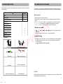
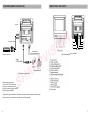
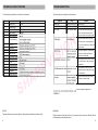
Car Rear Viewer
Operating Instruction
Please rea d this manual compl etel y before operating the unit
SAFETY INFORMATION
Before installing the unit, please read all the CAUTION S and WAR NINGS below.
WAR NING
Do not expos e the monito r or ca mera to exce ssive heat, cold or moist ure.
High v oltage is with in the monit or and openi ng of e nclosu re is o nly all owed to prof ession als.
Do not place heavy objec t on ca bles o r cove r them with rugs or carpe t.
Do not place cable s wher e they can be pinch ed or steppe d on.
CAUTION
To avo id dam age to elect ronic c ircuit, stop u sing th is pro duct w hile do ing we lding work t o the
autom obile.
Conne ct this unit o nly to o ther c ompat ible un its.
Make s ure al l cable s are conne cted properly, Imp roper c able c onnec tions m ay da mage the
camer a and the mo nitor.
Make s ure al l cable s are conne cted firmly, o r imag e effec t may be wo rsened or sy stem m ay
operat e abno rmally.
Conne cting c ables are no t allow ed to touch hot or rotatin g part s, such as en gine, v entila tor, et c.
Do not locate the m onitor near r adiato rs, ove ns or other h eat ge nerat ing ap plianc es and
equipm ent.
Leave at leas t a 2" space betwe en the monit or and walls , cabin ets or other o bjects to all ow air
circula tion a round the un it.
To pre vent in ternal heat b uild-u p with in the monito r, don’t bloc k the ventila tion opening s.
Turn o ff power to th e mon itor wh en co nnecti ng the came ra.
Monito rs are not de signe d to be water proof. Expos ure to rain o r wate r may d amag e the u nit.
Do not place the un it to su nlight direct ly.
Never immerse any comp onent in wat er, and do no t spra y clean ing. w hen c leanin g, use a dam p
Lint-fr ee clot h only.
e11
FDA
i
TABLE OF CONTENTS
Preface
PREFACE
Thanks for your purchasing of
System features...........................................................................................1
5.5-Inch Car Rear View er
Sy stem compositi on
Unit c ontain........ ... ... .... ... ....... .............. ... .... ... .............. ... .... ... .............. ... .... .2
Accessories.................................................................................................2
Sy stem ins tallation guide
Mounting monitor... .... ... ........ .... ... ........ .... ........... .... ....... ........ .... ... ........ .... ... .3
C onnecting power cable ......................................... .... ...................................3
System connecting.......................................................................................3
Monitor mounting(Figures indications)
Moun ting the support (Fig.1).... ... ... .... ... ... .............. ... ... .... ... ... .............. ... ... .... .4
Fixing t he monitor(Fig.2)................................ ........ ................................. .... ..4
Po rt con nection disp lay(Figures indica tions)
Po rt connection(Fig.3). ... ... ... ... ... ... ... ... ... ... .................................. ... ... ... ... ... ... 5
Sy stem connection display
Syste m connection (F ig.4)....... ... ... .... ... ... ........... ... ... .... ... ... .............. ... ... .... ... .6
Identifying the parts
Front and rear view of product (Fi g.5)....................... .... ...................................7
Technical specification
Technical specif ica tion.. ... ........ ... .... ........ ... .... .... ... ........ ... .... ........... .... ... .......8
Troubleshooting
System Features
5.5" Military-type Phosphor Cathode Ray Tube(CRT)
Wide voltage input adaptability: 11~32V DC
2 channels of audio/video input, 1 channel of audio/video composite output
Power/Stand-by mode option
Normal/Mirror image switch
Day/Night lightness option
Troubleshooting..........................................................................................9
Near Sunlight-readability
Double-sided PCB board for efficiently increasing anti-vibration ability (6.8G)
Contrast, brightness and volume adjustment
Built-in speaker
Adjustable Mounting Bracket
Sun shield included
ii
1
SYSTEM COMPOSITION
SYSTEM INSTALLATION GUIDE
Before using the product, please make sure that the package of product includes the
f ollowing item s.
Item
This mo nitor can be mounted by embedd ing t o the das h are a, hangin g from the tru ck
roof o r seati ng to any position w hich is suit ab le to the driver to o bserve th e images .
Quantity
Monitor
1
M ounting monitor
Monitor support
1
Support mounting screw
4
Power cable
1
Anti-vibration pad
1
1. Select a position to mount the monitor
2. W ell p osition the monit or support, mark the fixing hole position and drill fixing
holes
3. See Fig.1, put spring lockwasher on mounting screw to f ix th e monitor support
4. See Fig.2, f ix the monitor to the support with 4 a ngle adjustment screws
5. See Fig.3, connect cables according to port con nection diagram
Angle adjustment screw
4
System connecting cable
1
Direction indication film
1
Sun shield
1
Operating instruction
1
Connecting pow er c able
6. See Fig.4, Connect one end of the power cable(wire) to the right position on the
dashboard
7. connect the other end of the po wer cabl e(plug) to the monitor
System connecting
Accessories
7. See Fig.4, connect the monitor and the cam era with the system connecting cable.
You can link the monitor with at most 2 chan nels of cameras and 1 channel of
video/audio output
(AV signal cab le can be sel ective purchase)
Monito r support
Angle adjustment screw
Power cable
Su pport mounti ng screw
Sun shield
Direction indication film
WARNING
Syste m connecting ca ble
2
Anti-vibration pad
Elect rical shock or fire hazard. Do not try to service this uni t you rself. Service should
be handle d by qualifie d technicians.
3
MONITOR MOUNTING
PORT CONNECTION DISPLAY
Monito r support
1
Mounting surface
Spring lockwasher
2
4 5 6 7
3
Fig. 3 Port connection
1. Video output
2. Camera1 in put
3. Camera2 in put
4. Audio o utput
5. To exterior speaker
6. Normal/Mirror i mage sw itch
7. Power input
Su pport mounting screw
Fig.1 Mounting the support
Sun shield
D etail of ports
GND (ground)
Power of camera
Video input
Audio input
Port 2/C1
Mirro r
1 2
ON
An gle adjustment
screw
Turn the switch from up to down can switch the image
display from mirror to normal.
Normal
Port 6/MIRROR
5
Monitor sup port
Fig.2 Fixing the monitor
4
Po rt7/POW ER
Black to g round (G ND)
R ed to power supply
O range to reve rsing light
W hite to d imm er
5
SYSTEM CONNECTION DISPLAY
IDENTIFYING THE PARTS
M onitor
15
14
13
12
9
AV signa l cable s
10
1
2
3 4
5 6 7 8
Fron t vie w
P ower c able
11
Rear view
Fig.5 Front and rear view of product
Vid eo tap e reco rder
System
co nnect ing cable
Camera
4 3 2 1
To c ar das hboar d
Fig.4 System connect ion
Powe r cable connecti on
1. Red to DC1 2V power input
2. Brown to reversing control p owe r
3. Wh ite t o postern control power
4. Bla ck t o ground (GN D)
1. Power swit ch
2. Power indi cator
3. Contrast adjustmen t
4. Brightn ess adju stment
5. Volume ad justm ent
6. Camera1 switch
7. Camera2 switch
8. Day/Ni ght light ness option
9. Camera inp ut C 1
10. Camera in put C2
11. Video output
12. Audio out put
13. To exterio r speaker
14. Normal/M irror image switch
15. Power input
This product can be linked to 2 channels of cameras and 1 channel of video output
which connect to a video tape recorder for recording images.
6
7
TECHNICAL SPECIFICATIONS
TROUBLESHOOTING
The t echnical specification of monitor is listed below
Serial No.
Item
Solve problems according to t he t able belo w
Symptom
Specifications
Cause
Solution
1
Display device
5.5"CRT
Rolling image
2
Deflection angle
70°
Shrunk & Unstable image
Monitor improper voltage
check the voltage of power supply
3
Input voltage
11~32V(DC)
Black image
Monitor improper voltage
if ok, check fuse->check power cable,
4
Output voltage
10V(DC)
wires or connector(loose or broken?)
5
Power consumption
Max. 1A
If all above item are ok, replace monitor
6
Scanning frequency
CCIR:(H)15625Hz/(V)50Hz
White image
Monitor(horizontal control)
Replace monitor
Monitor/Camera
Check main system cable. Make sure
EIA:(H)15750Hz/(V)60Hz
all connectors are connected properly.
If ok, check 4 pin DIN monitor cable. If ok,
7
Video input
Composite video signal 1Vp-p 75Ohm
8
Video output
Composite video signal 1Vp-p 75Ohm
replace camera
Blurred image
Fog, mud, water or ice on
Clean camera porthole. If condensation
9
Horizontal resolution
420TV lines at maximum
10
Field resolution
420TV lines at maximum
camera lens or porthole
or moisture is visible inside camera,
11
Anti-vibration capability
6.8G
moisture in camera
initiate device immediately.
Monitor
Make sure ground and +12V DC source
12
Camera port
4-pin DIN socket
13
AV port
RCA socket
14
Sptorage temperature
-25°C~+70°C
15
Operating temperature
-0°C~+60°C
16
Dimensions
160(W)×147(H)×143(L)mm(without support and sun shield)
17
Parking dimensions
293(W)×268(H)×200(L)mm
Engine noise or Static lines
is in solid connection. Call tech-support
for assistance
No light displayed on monitor Broken fuse or low brightness level
Check whether the fuse is broken or
brightness adjustment has been turned
to the lowest level
No image
Improper plugging in
plug the connector properly or replace
connector or broken system the system connecting cable
connecting cable
If you still can not solve the problems, contact our tech-support engi neer for
assistance.
N OTICE
WARNING
The manufacturer reserves the right to change the specifications without notice.
Elect rical shock or fire hazard. Do not try to service this uni t you rself. Service should
be handle d by qualifie d technicians.
8
9
Guarantee Card
This card is an important evidence for m aintenance service for end-u ser.
Please keep it properly.
For proper operati on under normal condition, we provide the followin g se rvices:
1. Replacement within 3 months.
2. Free maintenance service within 1 ye ar.
3. Life maintenance service(when g uarantee pe riod expires, materia l cost is
needed
This card is invalid under the following cond ition:
1. Dam age of trouble due t o unproved dismantle, refitting or usin g parts which
do not sat isfy the specification requ irem ent s.
2. Operati on beyond requi red condition.
Name of User:
Purchase Date:
Model Number:
Product Description:
Contact Information of User
Address:
Post Code:
Tel:
Invoice Number:
Name of Distributor:
D istributor Sign and Stam p here: