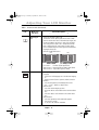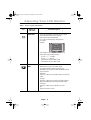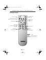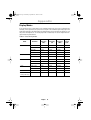
1
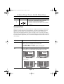
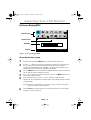
COVER.fm Page 1 Monday, September 18, 2000 8:43 AM
SyncMaster 210T
SyncMaster 240T
TFT-LCD Monitor
Owner’s
Instructions
COVER.fm Page 2 Monday, September 18, 2000 8:43 AM
Information in this document is subject to change without notice.
© 2000 Samsung Electronics Co., Ltd. All rights reserved.
Reproduction in any manner whatsoever without the written permission of Samsung Electronics Co.,
Ltd. is strictly forbidden.
Samsung Electronics Co., Ltd. shall not be liable for errors contained herein or for incidental or
consequential damages in connection with the furnishing, performance, or use of this material.
The Samsung logo and SyncMaster are registered trademarks of Samsung Electronics Co., Ltd.;
Microsoft, Windows ® and Windows® NT are registered trademarks of Microsoft Corporation; VESA,
DPMS and DDC are registered trademarks of Video Electronics Standard Association; the ENERGY STAR
name and logo are registered trademarks of the U.S. Environmental Protection Agency (EPA). As an
ENERGY STAR Partner, Samsung Electronics Co., Ltd. has determined that this product meets the ENERGY
STAR guidelines for energy efficiency. All other product names mentioned herein may be the trademarks
or registered trademarks of their respective owners.
Français
Deutsch
Portu-
Italiano
Safety Instructions. . . . . . . . . . . . . . . . . . . . . . . . . . . . . . . . . . . . . . . . . . . . . . . . . . . . . . . . . . . . . . . . . . . 2
Unpacking your Monitor . . . . . . . . . . . . . . . . . . . . . . . . . . . . . . . . . . . . . . . . . . . . . . . . . . . . . . . . . . . . . . 3
Setting up Your LCD Monitor . . . . . . . . . . . . . . . . . . . . . . . . . . . . . . . . . . . . . . . . . . . . . . . . . . . . . . . . . . 4
Setting up an Ergonomic Workstation . . . . . . . . . . . . . . . . . . . . . . . . . . . . . . . . . . . . . . . . . . . . . . . 4
Monitor Location . . . . . . . . . . . . . . . . . . . . . . . . . . . . . . . . . . . . . . . . . . . . . . . . . . . . . . . . . . . . 4
Workstation Height . . . . . . . . . . . . . . . . . . . . . . . . . . . . . . . . . . . . . . . . . . . . . . . . . . . . . . . . . . 4
Viewing Angle . . . . . . . . . . . . . . . . . . . . . . . . . . . . . . . . . . . . . . . . . . . . . . . . . . . . . . . . . . . . . . 4
Kensington Security Slot . . . . . . . . . . . . . . . . . . . . . . . . . . . . . . . . . . . . . . . . . . . . . . . . . . . . . . . . . . 4
Connecting Your LCD Monitor . . . . . . . . . . . . . . . . . . . . . . . . . . . . . . . . . . . . . . . . . . . . . . . . . . . . . 5
Plug and Play . . . . . . . . . . . . . . . . . . . . . . . . . . . . . . . . . . . . . . . . . . . . . . . . . . . . . . . . . . . . . . . . . . . 6
Installing the Video Driver . . . . . . . . . . . . . . . . . . . . . . . . . . . . . . . . . . . . . . . . . . . . . . . . . . . . . . . . . 6
Self-Test Feature Check (STFC) . . . . . . . . . . . . . . . . . . . . . . . . . . . . . . . . . . . . . . . . . . . . . . . . . . . . . 6
Getting Help . . . . . . . . . . . . . . . . . . . . . . . . . . . . . . . . . . . . . . . . . . . . . . . . . . . . . . . . . . . . . . . . . . . 7
Warm-up Time . . . . . . . . . . . . . . . . . . . . . . . . . . . . . . . . . . . . . . . . . . . . . . . . . . . . . . . . . . . . . . . . . 7
Adjusting Your LCD Monitor . . . . . . . . . . . . . . . . . . . . . . . . . . . . . . . . . . . . . . . . . . . . . . . . . . . . . . . . . . . 8
User Controls . . . . . . . . . . . . . . . . . . . . . . . . . . . . . . . . . . . . . . . . . . . . . . . . . . . . . . . . . . . . . . . . . . . 8
Automatic Save . . . . . . . . . . . . . . . . . . . . . . . . . . . . . . . . . . . . . . . . . . . . . . . . . . . . . . . . . . . . . . . . . 9
Direct-Access Features . . . . . . . . . . . . . . . . . . . . . . . . . . . . . . . . . . . . . . . . . . . . . . . . . . . . . . . . . . 10
OSD Lock/Unlock . . . . . . . . . . . . . . . . . . . . . . . . . . . . . . . . . . . . . . . . . . . . . . . . . . . . . . . . . . . . 10
ON-Screen Display (OSD) . . . . . . . . . . . . . . . . . . . . . . . . . . . . . . . . . . . . . . . . . . . . . . . . . . . . . . . . . 11
Accessing the Menu System . . . . . . . . . . . . . . . . . . . . . . . . . . . . . . . . . . . . . . . . . . . . . . . . . . 11
OSD functions and adjustments . . . . . . . . . . . . . . . . . . . . . . . . . . . . . . . . . . . . . . . . . . . . . . . 12
By Remote-Control . . . . . . . . . . . . . . . . . . . . . . . . . . . . . . . . . . . . . . . . . . . . . . . . . . . . . . . . . . 19
Appendix . . . . . . . . . . . . . . . . . . . . . . . . . . . . . . . . . . . . . . . . . . . . . . . . . . . . . . . . . . . . . . . . . . . . . . . . . 20
Power Saver . . . . . . . . . . . . . . . . . . . . . . . . . . . . . . . . . . . . . . . . . . . . . . . . . . . . . . . . . . . . . . . . . . . 20
Troubleshooting . . . . . . . . . . . . . . . . . . . . . . . . . . . . . . . . . . . . . . . . . . . . . . . . . . . . . . . . . . . . . . . . 21
Specifications . . . . . . . . . . . . . . . . . . . . . . . . . . . . . . . . . . . . . . . . . . . . . . . . . . . . . . . . . . . . . . . . . 23
Pin Assignmments . . . . . . . . . . . . . . . . . . . . . . . . . . . . . . . . . . . . . . . . . . . . . . . . . . . . . . . . . . . . . . 24
Display Modes . . . . . . . . . . . . . . . . . . . . . . . . . . . . . . . . . . . . . . . . . . . . . . . . . . . . . . . . . . . . . . . . . 25
Index . . . . . . . . . . . . . . . . . . . . . . . . . . . . . . . . . . . . . . . . . . . . . . . . . . . . . . . . . . . . . . . . . . . . . . . . . . . . 26
Español
Table of Contents
English
TOC.fm Page 1 Monday, September 18, 2000 8:42 AM
English
1
Safety.fm Page 2 Monday, September 18, 2000 8:43 AM
Safety Instructions
1
2
3
4
5
Before connecting the AC power cord to the DC adapter outlet, make sure the voltage
designation of the DC adapter corresponds to the local electrical supply.
Never insert anything metallic into the cabinet openings of the Liquid Crystal Display (LCD)
monitor; doing so may create the danger of electric shock.
To avoid electric shock, never touch the inside of the LCD monitor. Only a qualified
technician should open the case of the LCD monitor.
Never use your LCD monitor if the power cord has been damaged. Do not allow anything to
rest on the power cord, and keep the cord away from areas where people can trip over it.
Be sure to hold the plug, not the cord, when disconnecting the LCD monitor from an
electric socket.
6
Openings in the LCD monitor cabinet are provided for ventilation. To prevent overheating,
these openings should not be blocked or covered. Also, avoid using the LCD monitor on a
bed, sofa, rug, or other soft surface. Doing so may block the ventilation openings in the
bottom of the cabinet. If you put the LCD monitor in a bookcase or some other enclosed
space, be sure to provide adequate ventilation.
Put your LCD monitor in a location with low humidity and a minimum of dust.
7
8
9
10
11
12
13
14
Do not expose the LCD monitor to rain or use it near water (in kitchens, near swimming
pools, etc.). If the LCD monitor accidentally gets wet, unplug it and contact an authorized
dealer immediately. You can clean the LCD monitor with a damp cloth when necessary, but
be sure to unplug the LCD monitor first.
Place the LCD monitor on a solid surface and treat it carefully. The screen is made of thin
glass with a plastic front surface and can be damaged if dropped, hit or scratched. Do not
clean the front panel with keton-type materials (e.g., acetone), ethyl alcohol, toluene, ethyl
acid, methyl, or chloride – these may damage the panel.
Locate your LCD monitor near an easily accessible AC outlet.
If your LCD monitor does not operate normally – in particular, if there are any unusual
sounds or smells coming from it – unplug it immediately and contact an authorized dealer
or service center.
High temperature can cause problems. Don’t use your LCD monitor in direct sunlight, and
keep it away from heaters, stoves, fireplaces, and other sources of heat.
Unplug the LCD monitor when it is going to be left unused for an extended period of time.
Unplug your LCD monitor from the AC outlet before any service.
CAUTION
RISK OF ELECTRIC SHOCK
DO NOT OPEN
CAUTION: TO REDUCE THE RISK OF ELECTRIC SHOCK, DO NOT REMOVE COVER
(OR BACK).
NO USER-SERVICEABLE PARTS INSIDE.
REFER SERVICING TO QUALIFIED SERVICE PERSONNEL.
English
2
body2.fm Page 3 Monday, September 18, 2000 8:53 AM
Manual
Remote Controller
V1 V2
SOURCE
Monitor
DC Adapter
RCA Cable
15-pin D-Sub Signal Cable
S-VHS Cable
AUTO
EXIT
MENU
Speaker (option)
DVI-D signal cable
Italiano
Batteries
(AAA x 2)
PIP
Français
Warranty Card
(not available in all locations)
Deutsch
Power Cord
English
3
Portuguese
Installation CD
Español
Please make sure the following items are included with your monitor. If any items are missing,
contact your dealer.
English
Unpacking Your Monitor
body2.fm Page 4 Monday, September 18, 2000 8:53 AM
Setting up Your LCD Monitor
Setting up an Ergonomic Workstation
Consider the advice given below before you install your monitor.
Monitor location
Choose a position that exposes your monitor to the least reflection from lights or windows,
usually at a right angle to any window.
Workstation height
Place your LCD monitor so that the top of the screen is slightly below your eye level when you
are comfortably seated.
Viewing angle
Tilt the screen until you feel comfortable working with your monitor. The best viewing angle
can be obtained via AutoAngle™ provided by enclosed Colorific® software. Please install
the program to get the best viewing angle adjustment.
V1 V2
SOURCE
PIP
AUTO
EXIT
MENU
Figure 1. Tilt the screen
Kensington Security Slot
This monitor offers you the opportunity to secure your monitor using a Kensington-type
security device. Kensington lock is not included. Refer to your locking device documentation
for installation instructions.
Figure 2. Kensington-type security slot location
English
4
body2.fm Page 5 Monday, September 18, 2000 8:53 AM
English
Setting up Your LCD Monitor
Connecting Your LCD Monitor
PC
1
2
3
4
5
connector 1 on the back of the monitor.
Connect the Analog video signal cable from PC to 2 .
Connect RCA cable from external video devices such as VCR, DVD, and Camcorder to 4 .
Connect S-Video cable from external video devices such as VCR, DVD, and Camcorder to 5 .
If you have a DVI compliant video graphics adaptor, connect DVI video cable from PC to 3 .
Turn the monitor on, and then turn on the computer.
Now, install the monitor driver with accompanied utility CD.
Recommended resolution of SyncMaster240T is WUXGA, 1920 x 1200 @ 60HZ.
NOTE: Although the monitor is designed to be compatible with wide variety of popular video
adaptors, it is WUXGA, 1920x1200 mode, that needs special care. Since there is no
industry standard for WUXGA mode, video adaptor manufacturers are using several
different configurations that cause the monitor false video mode interpretation. If the
screen image is quality is poor when you are using either UXGA or WUXGA mode, please
check the followings.
1. UXGA mode identified as WUXGA mode
– Touch the “MENU” button, and then select “Hz”, information, icon.
– Read the information and make sure that the video mode says “1600x1200”
– If no resolution is appeared, then the monitor is in WUXGA mode.
2. WUXGA node identified as UXGA mode
– Touch the “MENU” button, and the select “HZ”, information, icon.
– Read the information and make sure that the video mode says only
“H_Sync... V_Sync...” without mentioning resolution.
– If you read 1600x1200, then the monitor is in UXGA mode.
English
5
Español
2.
3.
4.
5.
6.
7.
8.
Italiano
1. Connect the power cord to the DC adaptor and connect the adaptor plug to the DC14V power
Portuguese
Figure 3. Cable connections
Deutsch
Français
DC 14V
body2.fm Page 6 Monday, September 18, 2000 8:53 AM
Setting up Your LCD Monitor
If you are experiencing the above, then please follow the steps given below to solve the
problem.
1.Touch the “MENU” button to bring up OSD window.
2.Select “Hz” menu.
3.Press “MENU” button seven times while keeping “Hz” menu highlighted.
4.The monitor’s displayed mode will be changed from UXGA mode to WUXGA mode,
or from WUXGA mode to UXGA mode depending on the current mode.
Plug and Play
The adoption of the new VESA® Plug and Play solution eliminates complicated and time
consuming setup. It allows you to install your monitor in a Plug and Play compatible system
without the usual hassles and confusion. Your PC system can easily identify and configure
itself for use with your display. This monitor automatically tells the PC system its Extended
Display Identification Data (EDID) using Display Data Channel (DDC) protocols so the PC
system can automatically configure itself to use the flat panel display. If your PC system needs
a video driver, follow the instructions given below according to the operating system your
computer uses.
Installing the Video Driver
The CD that accompanies this product contains the necessary drivers for installing your
monitor. Please refer to the driver installation instructions included with your CD package for
more information.
Self-Test Feature Check (STFC)
Your monitor provides a self-test feature that allows you to check whether your monitor is
functioning properly. Make sure that PC is selected as a primary source by checking if the source
indicator LED labeled “PC” is on. If your monitor and computer are properly connected but the
monitor screen remains dark and the power indicator is blinking, run the monitor self-test by
following the steps given below:
Power Indicator
Figure 4. Power Indicator
English
6
body2.fm Page 7 Monday, September 18, 2000 8:53 AM
If the monitor is functioning properly, you will see a white box with a large blue oval Samsung
logo and an error messsage “CHECK SIGNAL CABLE.” in black color.
CHECK SIGNAL CABLE
Analog, Digital, Video or Svideo
Figure 5. Monitor self-test screen
Français
3 Turn on the monitor.
Deutsch
1 Turn off both your computer and the monitor.
2 Unplug the video cable from the back of the computer.
English
Setting up Your LCD Monitor
If your monitor screen remains blank after following the previous procedure, check your video
controller and computer system; your monitor is functioning properly.
Getting Help
If your monitor does not display an image, check your cable connections and refer to
"Troubleshooting" on page 21. If you experience difficulties with the quality of the displayed
image, run Auto Adjustment by touching “AUTO” control button. You may want to refer to
“Adjusting Your LCD Monitor” on page 8 or “Troubleshooting” on page 21.
Warm-up Time
All LCD monitors need time to become thermally stable whenever you turn on the monitor
after letting the monitor be turned off for a couple of hours. Therefore, to achieve more
accurate adjustments for parameters, allow the LCD monitor to warm (be on) for at least 20
minutes before making any screen adjustments.
English
7
Italiano
the monitor.
Portuguese
4 Turn off your monitor and reconnect the video cable; then turn on both your computer and
Español
This box also appears during normal operation if the video cable becomes disconnected or
damaged.
body2.fm Page 8 Monday, September 18, 2000 8:53 AM
Adjusting Your LCD Monitor
User Controls
Your LCD monitor allows you to easily adjust the characteristics of the image being displayed.
All of these adjustments are made using the control buttons on the front of the monitor. While
you use these buttons to adjust the controls, an On Screen Display shows you their numeric
values as they change.
V1 V2
SOURCE
PIP
AUTO
EXIT
MENU
* 21" : SyncMaster 210T
Figure 6. User control locations
No.
Name
1
Source
2
PIP
Description
n
n
n
n
n
n
3
Auto
4
Exit
n
n
n
n
5
Menu
Power
Activates PIP(Picture-in-Picture) window directly.
PIP to Fullscreen video.
PIP off.
Use this button to optimize image quality
automatically.
"Auto adjustment" feature affects following
parameters: Fine, Coarse, and Image Position.
Exits from menus and sub-menus.
Exits from the OSD system.
Turns the PIP off.
n
Opens the OSD and selects the highlighted
function.
n
Turns ON/OFF the monitor.
Indicates the status of the monitor.
-Green : Normal Operation.
-Amber : Power Saving Mode or Disconnected
Signal Cable.
n
6
Selects Video source.
Two source indicator LEDs on the left of the control
button indicate currently active Video source.
English
8
body2.fm Page 9 Monday, September 18, 2000 8:53 AM
7
n
Moves the selector right or left on the OSD.
Increases or decreases the Brightness.
Increases or decreases the values of the selected
function.
Automatic Save
Whenever you open the on-screen menu and allow an adjustment window to remain active
for about 3 seconds without pressing other buttons, the monitor automatically saves any
adjustment you have made. These changes are saved into a user area in the monitor.
The monitor can save adjustments for up to 4 user modes. It has 13 for 210T (15 for 240T )
factory preset or preload modes, one for each signal frequency as listed in table 7 on page 25.
If you have made no adjustments, the on-screen menu disappears and the monitor does not
save anything.
Function
SOURCE
Description
n
n
n
PIP
n
Use this button to change a video source
Video sources are changed in the following order:
D-sub DVI RCA S-VIDEO
Video: RCA/S-Video
PC: D-Sub/DVI (Analog/Digital)
Use this button to see both PC and Video the same time with either
PC or Video is in a small window superimposed on PC or Video.
Video
PC
D-sub/DVI
Video
RCA/S-Video
PC
Video
(RCA/S-Video)
PC
(D-sub/DVI)
V1 V2
SOURCE
PIP
AUTO
EXIT
MENU
V1 V2
SOURCE
PIP
AUTO
EXIT
MENU
*When PBP, Picture-By-Picture, is activated, PIP button performs
“Picture Swap.”
PC
D-sub
DVI
Video
RCA
S-Video
Video
RCA
S-Video
V1 V2
PC
D-sub
DVI
V1 V2
SOURCE
PIP
AUTO
Français
n
EXIT
English
MENU
SOURCE
9
PIP
AUTO
EXIT
MENU
Italiano
n
Deutsch
Description
Español
Name
Portuguese
No.
English
Adjusting Your LCD Monitor
body2.fm Page 10 Monday, September 18, 2000 8:53 AM
Adjusting Your LCD Monitor
Function
AUTO
Description
n
n
EXIT
Use this button to optimize image quality automatically.
“Auto adjustment” feature affects following parameters: Fine,
Coarse, and Image Position.
Exits from menus and sub-menus.
Exits from the OSD system.
Turns the PIP off.
n
n
n
–/+
n
Use this button to change “Brightness.”
When OSD is active, use “–” and “+” buttons to navigate through
menus.
MENU
n
Use this button to bring “OSD” menu.
POWER
n
Use this button to turn ON or OFF the monitor.
n
Direct-Access Features
Brightness
Follow these instructions to adjust the brightness.
-
+
25
1
With the menu off, push the “–” or “+” button
to display the brightness adjustment menu.
2
Push the “+” button to increase the
brightness; push the “–” button to decrease
the brightness.
OSD Lock/Unlock
This function allows you to secure the current settings so that they cannot be inadvertently
changed, while still allowing you to adjust the Brightness and Contrast.
You can unlock the OSD controls at any time by using the same procedure.
With the OSD screen off, push and hold the Menu button for at least 5 seconds to lock or
unlock the controls. When locked, a 'LOCKED!' message will be displayed along the bottom of
each OSD menu except for these screens :
• Brightness
• Contrast
English
10
body2.fm Page 11 Monday, September 18, 2000 8:53 AM
English
Adjusting Your LCD Monitor
On Screen Display(OSD)
Setting bar
-
+
Tool Tip
25
Press Menu Key
Figure 7. On Screen Display(OSD)
Accessing the menu system
NOTE: The numeric value indicator is provided as a point of reference only and has
nothing to do with a real measurement.
6
Push the Exit button a couple of times to return to the main menu to select another
function or to exit from the OSD.
English
11
Español
Use the "– , + " buttons to move from one function to another. As you move from one
icon to another, the function name changes to reflect the function or group of
functions represented by that icon. See Table 1 starting on the next page to view a
complete list of all of the functions available for the monitor.
Press the Menu button once to activate the highlighted function, then follow the Tool
Tips to select the function and adjust the value.
Use "–" and "+" buttons to select the sub-menu, and press the Menu button once to
activate the selected sub-menu.
After selecting a function, use the "– " and "+ " buttons to make necessary
adjustments. The setting bar moves and the numeric value indicator changes to reflect
your adjustments.
Italiano
3
4
5
With the OSD off, push the Menu button to display the main OSD menu.
Portuguese
1
2
Deutsch
BRIGHTNESS
Function name
Français
Function icons
body2.fm Page 12 Monday, September 18, 2000 8:53 AM
Adjusting Your LCD Monitor
OSD functions and adjustment
Table 1. Screen controls
Menus and
Sub-menus
Icon
Function Descriptions
–
+
Brightness
Changes the overall light intensity of the images being
displayed.
Contrast
Changes the ratio of light intensity between the
brightest white and the darkest black. If "CONTRAST"
ratio is set too high, color saturation occurs resulting
loss of details.
Image Lock
Image Lock is used to fine tune and get the best image
by removing noises that creates unstable images with
jitters and shimmers.
n
n
Fine
Coarse
The FINE and COARSE adjustments allow you to fine tune
image quality of the monitor. Use “– “ and “+” buttons to
set the corresponding values to remove or minimize horizontal and vertical noise shown in Figure A and Figure B
respectively.
Figure A
Figure B
V1 V2
SOURCE
V1 V2
SOURCE
English
12
PIP
AUTO
EXIT
MENU
PIP
AUTO
EXIT
MENU
body2.fm Page 13 Monday, September 18, 2000 8:53 AM
Fine
Coarse
H-Position
Although "Auto Adjustment" automatically finds the
optimum values of FINE and COARSE parameters as well
as IMAGE POSITION, it may be necessary for you to
adjust those parameters manually. It is recommended for
you to use "Auto Adjustment" first. If the adjustment
results are not satisfactory, then use COARSE and FINE
adjustment features to get the best adjustment results.
Bear in mind that COARSE and FINE adjustments may
change the width of the image and affect IMAGE
POSITION as well. If the image is clear while out of
center by a couple of pixels, use IMAGE POSITION to
center the image.
Changes the location of the image.
In case of the image is off center, use this function to
center the image.
n H-Position
“–” : Move to the LEFT
“+” : Move to the RIGHT
n V-Position
“–” : Move to the Bottom
“+” : Move to the Top
n
n
Color control
The tone of color can be changed from bluish white to redish white. The individual color components are also user
customizable.
Italiano
V-Position
Français
n
+
n
Mode 1
Redish white.
n
Mode 2
Plain white.
n
Mode 3
Bluish white.
n
User Mode
User customizable.
n
Reset
Color parameters are replaced with the factory default
values.
English
13
Portuguese
n
–
Deutsch
Function Descriptions
Menus and
Sub-menus
Icon
Español
Table 1. Screen controls (Continued )
English
Adjusting Your LCD Monitor
body2.fm Page 14 Monday, September 18, 2000 8:53 AM
Adjusting Your LCD Monitor
Table 1. Screen controls (Continued )
Function Descriptions
Menus and
Sub-menus
Icon
Image Size
–
+
Aspect ratio is the proportion of a vertical versus a
horizontal resolution, and it varies depending on the
input video resolution. For example, 640x480, 800x600,
and 1024x768 have the aspect ratio of 4:3, and
1280x1200 has the aspect ratio of 5:4. To view original
image without geometrical distortion, aspect ratio must
be preserved. The aspect ratio of SyncMaster240T is
16:10 that is neither 4:3 nor 5:4. Thus if the input image
resolution has the aspect ratio of 4:3 or 5:4, full screen
expansion to 16:10 makes image looked wider to the
horizontal direction. This is not appropriate especially for
those who do CAD, CAM, and Graphic oriented jobs. To
resolve this, IMAGE SIZE control provides three different
image expansion methods: Expanded 1, Expanded 2, and
Normal.
n
Expanded 1
Performs full screen image expansion regardless of the
aspect ratio of the input video resolution
n
Expanded 2
Performs image expansion while keeping the aspect ratio of
the original video resolution. Usually, there will be some
unfilled space to the horizon direction.
n
Normal
Performs no image expansion. In this mode, input video is
displayed at the center of the monitor as it is.
RECALL
n
n
Discards current setting and replaces corresponding parameters with the factory default values.
Geometry
Replace H-Position and V-Position values with the factory default values.
Color
Replace R,G, and B values with the factory default values.
Mode 1, Mode 2, Mode 3 and User Mode will be initialized.
English
14
body2.fm Page 15 Monday, September 18, 2000 8:53 AM
English
Adjusting Your LCD Monitor
Table 1. Screen controls (Continued )
Function Descriptions
n
n
n
n
Zoom
n
n
n
n
Pan
n
n
Performs Digital Zoom.
Any part of an image can be magnified by ZOOM
feature and the center of magnification can be
arbitrarily changed by PAN feature.
Magnifies an image
H-Pan
– Moves magnified image to the horizontal direction
– Same as changing the center of ZOOM to the
horizontal direction
V-Pan
– Moves magnified image to the vertical direction
– Same as changing the center of ZOOM to the
vertical direction
English
15
Français
Performs digital image quality compensation.
When an input video resolution is lower than
1920x1200 and if IMAGE SIZE is set to "Expanded 1" or
"Expanded 2," then depending on the input video
resolution, the expanded image becomes hazy or
blurred. In this case, applying sharpening filter
enhances the quality of the image, and SHARPNESS is
the features providing such Digital Image
Compensation Effects. SHARPNESS is applicable both
Composite Video signals fed by RCA or S-Video
connector and PC Video signals fed by D-Sub or DVI
connector.
Sharp
Makes image looked sharper
Medium
Makes image looked sharper but not as sharper as
"Sharp"
Soft
Makes image looked smoother
Deutsch
n
Español
n
+
Italiano
Sharpness
–
Portuguese
Menus and
Sub-menus
Icon
body2.fm Page 16 Monday, September 18, 2000 8:53 AM
Adjusting Your LCD Monitor
Table 1. Screen controls (Continued )
Function Descriptions
Menus and
Sub-menus
Icon
PIP(Picture-inPicture)
–
n
n
n
n
n
Size
n
Position
+
Shows a small sub-window superimposed on Video or
PC. (Refer to page 9.)
When Video is a full screen video source, then PC will
be appeared in a small window. Likewise, when PC is a
full screen video source, then Video will be appeared in
a small window.
The monitor remembers the previous state of Video
and PC. Thus if the previous state of PC was S-Video,
and currently PC video is displayed in full screen, then
S-Video will appear in the PIP window.
When you touch PIP button when PIP feature is active,
PIP source will be changed from RCA or S-Video to SVideo or RCA respectively, and from D-Sub or DVI to
DVI or D-Sub respectively.
Off: Disables PIP
1: 400 x 300
2: 640 x 480
3: 800 x 600
n
n
H-Position
Changes PIP window position to the horizontal direction.
V-Position
Changes PIP window position to the vertical direction.
English
16
body2.fm Page 17 Monday, September 18, 2000 8:53 AM
English
Adjusting Your LCD Monitor
Table 1. Screen controls (Continued )
Function Descriptions
n
Shows PC and Video side by side.
The monitor screen splits by half and one side is filled
with PC and the other side is filed with Video. Again, the
monitor remembers the previous state of PC and Video.
Thus if the previous state of PC is D-Sub and currently
RCA is displayed in full screen mode, PC video signal
from D-sub and Composite video signal from RCA will be
displayed side by side.
PBP OFF: Disable PBP feature
PBP1
PBP2
PC
Video
Video
PC
D-SUB
RCA
RCA
D-SUB
DVI
S-Video
S-Video
SOURCE
n
n
n
MENU CONTROL
n
n
n
n
n
PC Source 1:
PC Source 2:
Video Source 1:
Video Source 2:
DVI
V1 V2
V1 V2
n
PIP
AUTO
EXIT
MENU
SOURCE
PIP
AUTO
EXIT
MENU
PC Video Signal Analog (D-Sub)
PC Video Signal Digital (DVI)
Normal Composite Video Signal (RCA)
Super Video Signal (S-Video)
Sets up OSD appearances
Language
– Selects one OSD language out of six different languages
– English /German /French /Spanish /Italian /Swedish
Halftone
– Sets the transparency of the background of OSD
– Use “–” and “+ “buttons to adjust values
Menu Position
– Sets OSD window display position
– H-Position: Moves OSD window to the horizontal direction
– V-Position: Moves OSD window to the vertical direction
Menu Duration
– Sets time span before OSD window disappears.
– The units are seconds.
– 5 / 10 / 20 / 50 / 200 are selectable.
English
Français
n
17
Deutsch
n
+
Español
Picture by picture
–
Italiano
Menus and
Sub-menus
Portuguese
Icon
body2.fm Page 18 Monday, September 18, 2000 8:53 AM
Adjusting Your LCD Monitor
Table 1. Screen controls (Continued )
Icon
Function Descriptions
Menus and
Sub-menus
Information
–
n
n
n
n
n
n
+
Shows the information of the current video signal.
The information includes the following
Video Signal Type: Analog/Digital
Sync. Types and frequencies with polarities
Resolution
Example
ANALOG
H + 74.8 V - 59.8
1920 x 1200
V1 V2
SOURCE
n
n
VIDEO CONTROL
n
n
n
n
n
n
PIP
AUTO
EXIT
MENU
The example shown above says the following.
Video Signal Type: Analog PC video
H_Sync: “+ / + ” 74.8 kHz
V_Sync: “– / –” 59.8 HZ
S/M 210T Resolution: 1600 x 1200
S/M 240T Resolution: 1920 x 1200
The color characteristic of Composite Video is often
different from the one of PC Video signal.
Use VIDEO CONTROL feature to adjust Color
Characteristic of Composite Video independent of the
one of PC Video.
Brightness
Increases or decreases the light intensity of composite
video.
Contrast
Increases or decreases the ratio of the light intensity
between the brightest white and the darkest dark.
Saturation
Increases or decreases the pureness of color.
Hue
Changes the tone of colors.
English
18
body2.fm Page 19 Monday, September 18, 2000 8:53 AM
English
Adjusting Your LCD Monitor
By Remote-Control
Menu Key
Exit Key
Auto Adjustment
PIP Off
PBP On, PIP Picture
Swap
Change PIP Size
Zoom In
PBP Enable
(PBP disable: Exit)
Deutsch
Display Current State
(Right Up Corner Message)
Français
Input Source
Change.
Power On/Off
– key
+ Key
Only Used In PIP, Pan
Only Used In PIP, Pan
English
19
Portuguese
Italiano
Left Key:
Right Key:
Up Key:
Down Key:
Español
Zoom Out
(Zoom Exit: Exit)
body2.fm Page 20 Monday, September 18, 2000 8:53 AM
Appendix
PowerSaver
This monitor has a built-in power management system called PowerSaver. This system saves
energy by switching your monitor into a low-power mode when it has not been used for a
certain period of time. The available modes are “On”, “Standby”, “Sleep”, and “Deep Sleep”.
Power Saver operates with a VESA DPMS compliant video card installed in your computer.
You use a software utility installed on your computer to set up this feature. See Table 2 below
for details.
Table 2. Power-saving modes
Power-Saving Function mode (EPA/NUTEK)
State
Normal
Operation
Standby Mode
Sleep Mode
Position A1
Deep Sleep Mode
Position A2
Horizontal Sync Active
Vertical Sync
Active
Video
Active
Inactive
Active
Blanked
Active
Inactive
Blanked
Inactive
Inactive
Blanked
Power
Indicator
Green
Amber
Amber Blinking Amber Blinking
(0.5 sec interval) (1 sec. interval)
Power
Consumption
210T: 75W(Max.)
240T: 80W(Max.)
Less than 5W
Less than 5W
Less than 5W
NOTE: This monitor automatically returns to normal operation when horizontal and vertical
sync return. This occurs when you move the computer’s mouse or press a key on the
keyboard.
*This monitor is EPA ENERGY STAR® compliant and NUTEK compliant when used with a
computer equipped with VESA DPMS functionality.
For energy conservation, turn your monitor OFF when you are not using it or when leaving it
unattended for long periods.
NOTE: Maximum power consumption is measured after letting the monitor turned on for 30
minuites that is the time required for the unit to be thermally stable.
English
20
body2.fm Page 21 Monday, September 18, 2000 8:53 AM
Troubleshooting
If you have a problem setting up or using your LCD monitor, you may be able to solve it
yourself. Before contacting customer service, try the suggested actions that are appropriate
to your problem.
English
Appendix
n
Ensure that the power cord is
firmly connected and the LCD
monitor is on.
Connecting your LCD
monitor, page 5.
“ Check Signal Cable”
message
n
Ensure that the signal cable is
firmly connected to the PC or
video sources.
Ensure that the PC or video
sources are turned on.
Connecting your LCD
monitor, page 5.
Check the maximum resolution
and the frequency of the video
adaptor.
Compare these values with the
data in the Display Modes
Timing Chart.
Display Modes, page 25.
n
“Sync. Out of Range”
message
n
n
Español
Screen is blank and
power indicator is off
The image is too light
or too dark
n
Adjust the Brightness and
Contrast.
Brightness, page 12.
Contrast, page 12.
Horizontal bars appear
to flicker, jitter or
shimmer on the image
n
Adjust the Fine function.
Image Lock, Fine,
page 12.
Vertical bars appear to
flicker, jitter or
shimmer on the image.
n
Adjust the Coarse function and
then adjust the Fine function.
Image Lock, Coarse,
page 12.
Image Lock, Fine, page 12.
English
21
Deutsch
Reference
Italiano
Suggested Actions
Portuguese
What you see...
Français
Table 3. Troubleshooting – Image
body2.fm Page 22 Monday, September 18, 2000 8:53 AM
Appendix
Table 3. Troubleshooting – Image (Continued )
What you see...
Suggested Actions
Screen is blank and
power indicator light is
steady amber or blinks
every 0.5 or 1 seconds
n
Image is not stable and
may appear to vibrate
Reference
The monitor is using its power
management system.
Move the computer’s mouse or
press a key on the keyboard
Power Saver, page 20.
n
Check that the display
resolution and frequency from
your PC or video board is an
available mode for your monitor.
On your computer check: Control
Panel, Display, Settings
Display Modes, page 25.
n
If the setting is not correct, use
your computer utility program to
change the display settings.
Installing the Video Driver,
page 6.
n
NOTE: Your monitor supports multiscan display functions within
the following frequency domain:
n
Horizontal frequency:
Vertical frequency:
Maximum refresh rate:
30 kHz-81 kHz
56 Hz-85 Hz
210T: 1600 x 1200 @ 60Hz
240T: 1920 x 1200 @ 60Hz
Image is not centered
on the screen.
n
Adjust the horizontal and
vertical position.
H-Position, page 13.
V-Position, page 13.
You need the monitor
driver software
n
Download the driver from WWW
pages:
http://samsungelectronics.com/
support/downloads/monitor/
index.html
English
22
body2.fm Page 23 Monday, September 18, 2000 8:53 AM
English
Appendix
Specifications
Table 4. Technical and environmental specifications
30 – 81 kHz
56 – 85 Hz
16,777,216 colors
Display
Resolution
1920 x 1200 @ 60 Hz
Input Signal
Sync.
Deutsch
Horizontal
Vertical
Display color
24.06” Diagonal
518.4 (H) x 324 (V) mm
a-si TFT Active matrix
0.27 (H) x 0.09 (V) mm
80˚/80˚/80˚/80˚
Video signal
H/V Separate, TTL, P. or N.
H/V Composite, TTL, P. or N.
Sync-on-green 0.3 Vp-p, N.
0.7 Vp-p @ 75 ohm
Power Supply
Input
Output
AC 100-240 Vrms (50 ~ 60Hz )
DC 14V/6A
Power
Consumption
Maximum
Power Saving
75 W
5W
80 W
5W
Dimensions/
Weight
(WxHxD)
unit
549.1 x 228 x 483.4mm
/11.3 kg
650 x 586 x 330mm
/16.3 kg
620.4 x 228 x 483.4mm
/13.8 kg
722 x 586 x 330mm
/17.25 kg
carton
Environmental Operating Temperature: 50 ˚F to 104 ˚F (10 ˚C to 40 ˚C)
Considerations Operating Humidity:
10% to 80%
Storage Temperature: 13 ˚F to 113 ˚F (-25 ˚C to 45 ˚C)
Storage Humidity:
5% to 95%
NOTE: Maximum power consumption is measured after letting the monitor turned on for 30
minuites that is the time required for the unit to be thremally stable.
* Referring to preset timing modes, page 25.
English
23
Español
21.3” Diagonal
432 (H) x 324 (V) mm
a-si TFT Active matrix
0.27 (H) x 0.27 (V) mm
80˚/80˚/80˚/80˚
Italiano
* Frequency
Size
Display Size
Type
Pixel pitch
Viewing Angle
Portuguese
Panel
240T
Français
210T
body2.fm Page 24 Monday, September 18, 2000 8:53 AM
Appendix
Pin Assignments
Table 5. 15 pin D-sub connector
Pin
Separate H/V
Composite H/V
Sync-on-green
1
Red
Red
Red
2
Green
Green
Green + H/V Sync
3
Blue
Blue
Blue
4
GND
GND
GND
5
GND (DDC Return)
GND (DDC Return)
GND (DDC Return)
6
GND-Red
GND-Red
GND-Red
7
GND-Green
GND-Green
GND-Green
8
GND-Blue
GND-Blue
GND-Blue
9
No Connection
No Connection
Not used
10
GND-Sync/Self Test
GND-Sync/Self Test
GND-Sync/Self Test
11
GND
GND
GND
12
DDC _SDA
DDC _SDA
DDC _SDA
13
H_Sync
H/V Sync
Not used
14
V_ Sync
Not used
Not used
15
DDC _SCL
DDC _SCL
DDC _SCL
Table 6. DVI-D Connector
Pin
Signal Assigneut
Pin
Signal Assigneut
1
T.M.D.S Data 2-
13
No Connect
2
T.M.D.S Data 2+
14
15V Power
3
T.M.D.S Data 2 Shield
15
Ground (for 15V)
4
No Connect
16
Hot Plug Detect
5
No Connect
17
T.M.D.S Data 0-
6
DDC Clock
18
T.M.D.S Data 0+
7
DDC Clock
19
T.M.D.S Data 0 Shield
8
No Connect
20
No Connect
9
T.M.D.S Data 1-
21
No Connect
10
T.M.D.S Data 1+
22
T.M.D.S Clock Shield
11
T.M.D.S Data 1Shield
23
T.M.D.S Clock +
12
No Connect
24
English
T.M.D.S Clock -
24
body2.fm Page 25 Monday, September 18, 2000 8:53 AM
Horizontal
Frequency
(kHz)
Vertical
Frequency
(Hz)
Pixel Clock
Frequency
(MHz)
Sync
Polarity
(H/V)
720 x 400
31.469
70.087
28.322
–/+
640 x 480
31.469
59.940
25.175
–/–
640 x 480
37.500
75.000
31.500
–/–
640 x 480
43.269
85.008
36.000
–/–
800 x 600
46.875
75.000
49.500
+/+
800 x 600
53.674
85.061
56.250
+/+
1024 x 768
48.363
60.004
65.000
–/–
1024 x 768
60.023
75.029
78.750
+/+
1024 x 768
68.677
84.997
94.500
+/+
1280 x 1024
63.981
60.020
108.000
+,–/+,–
1280 x 1024
79.976
75.025
135.000
+/+
UXGA
1600 x 1200
75.000
60.000
+,–/+,–
WUXGA
(Analog/240T only)
1920 x 1200
75.000
60.000
+,–/+,–
SVGA
XGA
SXGA
Italiano
VGA
Resolution
English
25
Portuguese
Mode
Français
Table 7. Preset timing modes
Deutsch
If the signal from the system equals to the standard signal mode, the screen is adjusted automatically. If the signal from the system doesn't equal to the standard signal mode, adjust the
mode with referring to the Videocard user guide because the screen might not display or only
the power LED might be on. For the display modes listed below, the screen image has been
optimized during manufacture.
Español
Display Modes
English
Appendix
IX.fm Page 26 Monday, September 18, 2000 8:42 AM
Index
Numerics
K
15-pin D-sub connector 24
Kensington security slot 4
A
M
Automatic Save 9
Menu 8
Monitor self-test screen 7
B
Brightness 12
O
C
OSD Lock/Unlock 10
ON Screen Display 11
Cable connections 5
Coarse 13
Color Control 13
Contrast 12
P
PIP 8, 16
Power 8
Power Indicator 6
D
S
DC adapter 3
Display Modes 25
E
Safety Instructions 2
Self-Test Feature Check 6
Exit 10
T
F
Tilt the screen 4
Troubleshooting 21
Fine 13
Function icons 11
U
H
User control locations 8
H-position 13
V
I
V-position 13
Image lock 12
Image size 14
Information 18
English
26
Changes or modifications not expressly approved by the
party responsible for compliance could void the user’s
authority to operate the equipment.
If necessary, consult your dealer or an experienced radio/
television technician for additional suggestions. You may
find the booklet called How to Identify and Resolve Radio/
TV Interference Problems helpful. This booklet was
prepared by the Federal Communications Commission. It is
available from the U.S. Government Printing Office,
Washington, DC 20402, Stock Number 004-000-00345-4.
Warning
User must use shielded signal interface cables to maintain
FCC compliance for the product.
Declaration of conformity for products
Marked with FCC Logo
This device complies with Part 15 of the FCC Rules.
Operation is subject to the following two conditions: (1)
this device may not cause harmful interference, and (2) this
Français
This Class B digital apparatus meets all requirements of
the Canadian Interference-Causing Equipment Regulations
of ICES-003.
Cet appareil Numérique de classe B respecte toutes les
exigences du Règlemont ICES-003 sur les équipements
produisant des interférences au Canada.
Español
User Information
IC Compliance Notice
MPR II Compliance
This monitor complies with SWEDAC(MPR II)
recommendations for reduced electric and magnetic fields.
European Notice
Products with the CE Marking comply with both the EMC
Directive (89/336/EEC), (92/31/EEC), (93/68/EEC) and the
Low Voltage Directive (73/23/EEC) issued by the
Commission of the European Community.
Compliance with these directives implies conformity to the
following European Norms:
n EN55022:1998 – Radio Frequency Interference
n EN55024:1998 – Electromagnetic Immunity
n EN61000-3-2:1995 + A1 + A2 – Power Line Harmonics
n EN61000-3-3:1995 – Voltage Fluctuations
n EN60950 – Product Safety.
Italiano
User Instructions
The Federal Communications Commission Radio
Frequency Interference Statement includes the following
warning:
Note: This equipment has been tested and found to
comply with the limits for a Class B digital device, pursuant
to Part 15 of the FCC Rules. These limits are designed to
provide reasonable protection against harmful
interference in a residential installation. This equipment
generates, uses, and can radiate radio frequency energy
and, if not installed and used in accordance with the
instructions, may cause harmful interference to radio
communications. However, there is no guarantee that
interference will not occur in a particular installation.
If this equipment does cause harmful interference to radio
or television receptions, which can be determined by
turning the equipment off and on, the user is encouraged to
try to correct the interference by one or more of the
following measures:
n Reorient or relocate the receiving antenna.
n Increase the separation between the equipment and
receiver.
n Connect the equipment into an outlet on a circuit
different from that to which the receiver is connected.
n Consult the dealer or an experienced radio/TV
technician for help.
device must accept any interference received, including
interference that may cause undesired operation.
The party responsible for product compliance:
SAMSUNG ELECTRONICS CO., LTD
America QA Lab of Samsung
85 West Tasman Drive
San Jose, CA 95134 USA
Tel) 408-544-5124
Fax) 408-544-5191
Provided with this monitor is a detachable power supply
cord with IEC320 style terminations. It may be suitable for
connection to any UL Listed personal computer with similar
configuration. Before making the connection, make sure
the voltage rating of the computer convenience outlet is
the same as the monitor and that the ampere rating of the
computer convenience outlet is equal to or exceeds the
monitor voltage rating.
For 120 Volt applications, use only UL Listed detachable
power cord with NEMA configuration 5-15P type (parallel
blades) plug cap. For 240 Volt applications use only UL
Listed Detachable power supply cord with NEMA
configuration 6-15P type (tandem blades) plug cap.
Portuguese
FCC Information
Deutsch
Regulatory Information
English
regulat.fm Page 0 Monday, September 18, 2000 8:52 AM
240T(E)BkCov.fm Page iv Monday, September 18, 2000 8:43 AM
U.S.A. :
ESPAÑA :
Samsung Electronics America (SEA)
One Samsung Place
Ledgewood, NJ 07852
Tel. : 1-800-SAMSUNG (1-800-726-7864)
Samsung Electrónics Comercial Ibérica, S.A.
Ciencies, 55-65 (Polígono Pedrosa) 08908
Hospitalet de Llobregat (Barcelona)
Tel. : (93) 261 67 00
Fax. : (93) 261 67 50
CANADA :
Samsung Electronics Canada Inc.
7037 Financial Drive
Mississauga, Ontario L5N 6R3
Tel. : 1-800-SAMSUNG (1-800-726-7864)
Fax. : (905) 542-1199
GERMANY :
Samsung Electronics GmbH Samsung-Haus
Am Kronberger Hang 6/65824 Schwalbach/Ts.
Tel. : 06196-66-1134
Fax. : 06196-66-1133
AUSTRALIA :
Samsung Electronics Australia Pty Ltd.
Unit G, 10-16 South Street,
Rydalmere, N.S.W. 2116
P.O. BOX 368
Tel. : (02) 638-5200
ITALIA :
Samsung Electronics Italia SpA
Via C. Donat Cattin,
5-20063 Cernusco sul Naviglio (Mi)
Tel. : 167-010740
PANAMA :
Servicios Samsung (Zona Libre), S.A.
50 and 61 Streets Sta, Cecilia
Bdl. Don Camilo, Panama City
Tel. : (507) 264-0195 or 269-5571
Fax : (507) 269-5568
UK :
Samsung Electronics (UK) Ltd.
Samsung House, 225 Hook Rise South
Surbiton, Surrey KT6 7LD
Tel. : (0181) 391 0168
Fax. : (0181) 397 9949
<European Service Center & National Service>
Stafford Park 12 Telford, Shropshire, TF3 3BJ
Tel. : (01952) 292 262
Fax. : (01952) 292 033
THAILAND :
Samsung Service Center
729-729/1 JSP Tower Rachadapisek RD.,
Bangpongpang, Yannawa, Bangkok 10120
Tel : (662) 2954508-14
Fax : (662) 2954267
SOUTH AFRICA :
Samsung Electronics South Africa
Somerset Office Park 5 Libertas Road
Bryanston, South Africa
Tel : (27)-11-463-5678
Fax : (27)-11-463-5215
BRASIL :
MEXICO
Samsung Eletrônica da Amazonia Ltda.
R. Prof. Manoelito de Ornellas, 303-2º Andar
Chácara Sto. Antônio • cep : 04719-040
São Paulo • SP
Tel. : (011) 541-8500
Fax : (011) 523-3995, 522-0726
Samsung Electronics Mexico S.A. de C.V.
Saturno 44 Col. Nva. Industrial Vallejo
Del. Gustavo A. Madero C.P. 07700
Mexico D.F.
Tel. 5747-5100
RFC: SEM950215S98
Samsung Electronics Svenska, AB
Box 713, S-194 27 Upplands Vasby
Tel.: (468) 590-966-00
Fax : (468) 590-966-50
SWEDEN:
IMPORTADO POR:SAMSUNG ELECTRONICS MEXICO S.A. DE C.V.
SATURNO 44 COL. NVA. INDUSTRIAL VALLEJO
DEL. GUSTAVO A. MADERO C.P. 07700
MEXICO D.F.
TEL. 5747-5100
RFC: SEM950215S98
EXPORTADO POR: SAMSUNG ELECTRONICS CO.,LTD.
JOONG-ANG DAILY NEWS BLDG.
7 SOON-WHA-DONG CHUNG-KU,
C.P.O BOX 2775, 1144 SEOUL, KOREA
“As an ENERGYSTAR® Partner, SAMSUNG has
determined that this product meets the
ENERGYSTAR® guidelines for energy efficiency.”
P/N: BN68-00177A-00
Printed on recyclable paper