1
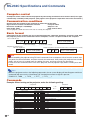
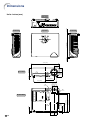
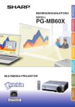
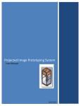
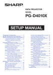
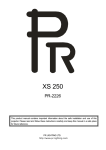
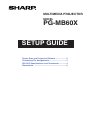
MULTIMEDIA PROJECTOR
MODEL
PG-MB60X
SETUP GUIDE
Screen Size and Projection Distance ................... 2
Connecting Pin Assignments ................................ 3
RS-232C Specifications and Commands ............. 4
Dimensions ............................................................. 6
Screen Size and Projection Distance
The projection screen size varies according to the distance from the lens of the projector to the screen.
Install the projector so that projected images are projected onto the screen at the optimum size by referring
to the table below. Use the values in the table as a reference when installing the projector.
Side View
Screen
H
Lens center
L
NORMAL Mode (4:3)
Diag. [ χ ]
300" (762 cm)
250" (635 cm)
200" (508 cm)
150" (381 cm)
100" (254 cm)
84" (213 cm)
72" (183 cm)
60" (152 cm)
40" (102 cm)
χ:
L:
L1:
L2:
H:
Picture (Screen) size
Width
Height
610 cm (240") 457 cm (180")
508 cm (200") 381 cm (150")
406 cm (160") 305 cm (120")
305 cm (120") 229 cm (90")
203 cm (80") 152 cm (60")
171 cm (67") 128 cm (50")
146 cm (58") 110 cm (43")
122 cm (48")
91 cm (36")
81 cm (32")
61 cm (24")
Projection
Minimum [L1]
9.1 m (29' 9")
7.6 m (24' 9")
6.0 m (19'10")
4.5 m (14'10")
3.0 m (9'11")
2.5 m (8' 4")
2.2 m (7' 2")
1.8 m (5'11")
1.2 m (4' 0")
distance [L]
Distance from the bottom of the image to
the lens center [H]
Maximum [L2]
13.7 m (44' 9")
–10.2 cm (–4 1/64")
11.4 m (37' 4")
–8.5 cm (–3 11/32")
9.1 m (29'10")
–6.8 cm (–2 43/64")
6.8 m (22' 5")
–5.1 cm (–2 1/64")
4.6 m (14'11")
–3.4 cm (–1 11/32")
3.8 m (12' 6")
–2.9 cm (–1 1/8")
3.3 m (10' 9")
–2.4 cm
(–31/32")
2.7 m (8'11")
–2.0 cm
(–51/64")
1.8 m (6' 0")
–1.4 cm
(–17/32")
Picture size (diag.) (in/cm)
Projection distance(m/ft)
Minimum projection distance (m/ft)
Maximum projection distance (m/ft)
Distance from the bottom of the image to the lens center (cm/in)
The formula for picture size and projection distance
[m/cm]
[Feet/inches]
L1 (ft) = 0.0302χ / 0.3048
L1 (m) = 0.0302χ
χ
L2 (m) = 0.0455
L2 (ft) = 0.0455χ / 0.3048
χ
H (in) = –0.034χ / 2.54
H (cm) = –0.034
STRETCH Mode (16:9)
Diag. [ χ ]
250" (635 cm)
225" (572 cm)
200" (508 cm)
150" (381 cm)
133" (338 cm)
106" (269 cm)
100" (254 cm)
92" (234 cm)
84" (213 cm)
72" (183 cm)
60" (152 cm)
40" (102 cm)
χ:
L:
L1:
L2:
H:
Picture (Screen) size
Width
Height
553 cm (218") 311 cm (123")
498 cm (196") 280 cm (110")
443 cm (174") 249 cm (98")
332 cm (131") 187 cm (74")
294 cm (116") 166 cm (65")
235 cm (92") 132 cm (52")
221 cm (87") 125 cm (49")
204 cm (80") 115 cm (45")
186 cm (73") 105 cm (41")
159 cm (63")
90 cm (35")
133 cm (52")
75 cm (29")
89 cm (35")
50 cm (20")
Projection
Minimum [L1]
8.2 m (27' 0")
7.4 m (24' 3")
6.6 m (21' 7")
4.9 m (16' 2")
4.4 m (14' 4")
3.5 m (11' 5")
3.3 m (10'10")
3.0 m (9'11")
2.8 m (9' 1")
2.4 m (7' 9")
2.0 m (6' 6")
1.3 m (4' 4")
distance [L]
Distance from the bottom of the image to
the lens center [H]
Maximum [L2]
12.4 m (40' 8")
–61.1 cm (–24 5/64")
11.2 m (36' 7")
–55.0 cm (–21 43/64")
9.9 m (32' 6")
–48.9 cm (–19 17/64")
7.4 m (24' 5")
–36.7 cm (–14 14/32")
6.6 m (21' 8")
–32.5 cm (–12 13/16")
5.3 m (17' 3")
–25.9 cm (–10 13/64")
5.0 m (16' 3")
–24.5 cm (–9 5/8")
4.6 m (15' 0")
–22.5 cm (–8 55/64")
4.2 m (13' 8")
–20.5 cm (–8 3/32")
3.6 m (11' 9")
–17.6 cm (–6 15/16")
3.0 m (9' 9")
–14.7 cm (–5 25/32")
2.0 m (6' 6")
–9.8 cm (–3 55/64")
Picture size (diag.) (in/cm)
Projection distance(m/ft)
Minimum projection distance (m/ft)
Maximum projection distance (m/ft)
Distance from the bottom of the image to the lens center (cm/in)
The formula for picture size and projection distance
[m/cm]
[Feet/inches]
L1 (m) = 0.0329χ
L1 (ft) = 0.0329χ / 0.3048
L2 (m) = 0.04957χ
L2 (ft) = 0.04957χ / 0.3048
H (cm) = –0.24459χ
H (in) = –0.24459χ / 2.54
Note
• There may be an error of ± 3% in the above values.
• Values with a minus (–) sign indicate that the lens center is lower than the bottom of the image.
-2
Connecting Pin Assignments
INPUT 1/INPUT 2 and OUTPUT RGB Signal Terminal: 15-pin Mini D-sub female connector
RGB Input
11
15
1
6
5
10
1.
2.
3.
4.
5.
6.
7.
8.
9.
10.
11.
12.
13.
14.
15.
Component Input
Video input (red)
Video input (green/sync on green)
Video input (blue)
Not connected
Not connected
Earth (red)
Earth (green/sync on green)
Earth (blue)
Not connected
GND
Not connected
Bi-directional data
Horizontal sync signal: TTL level
Vertical sync signal: TTL level
Data clock
1.
2.
3.
4.
5.
6.
7.
8.
9.
10.
11.
12.
13.
14.
15.
PR (CR)
Y
PB (CB)
Not connected
Not connected
Earth (PR)
Earth (Y)
Earth (PB)
Not connected
Not connected
Not connected
Not connected
Not connected
Not connected
Not connected
RS-232C Terminal: 9-pin Mini DIN female connector
1
2
4
5
6
3
Pin No.
1
2
3
4
5
6
7
8
9
Signal
Name
I/O
RD
SD
Receive Data
Send Data
SG
Signal Ground
Input
Output
RS
CS
Reference
Not connected
Connected to internal circuit
Connected to internal circuit
Not connected
Connected to internal circuit
Not connected
Connected to Pin 8
Connected to Pin 7
Not connected
9
7
8
DIN-D-sub RS-232C adaptor: 9-pin D-sub male connector
1
6
5
Pin No.
1
2
3
4
5
6
7
8
9
9
Signal
Name
I/O
RD
SD
Receive Data
Send Data
SG
Signal Ground
Input
Output
RS
CS
Reference
Not connected
Connected to internal circuit
Connected to internal circuit
Not connected
Connected to internal circuit
Not connected
Connected to internal circuit
Connected to internal circuit
Not connected
Note
• Pin 8 (CS) and Pin 7 (RS) are short circuited inside the projector.
RS-232C Cable recommended connection: 9-pin D-sub female connector
5
9
Pin No.
1
2
3
4
5
6
7
8
9
1
6
Signal
CD
RD
SD
ER
SG
DR
RS
CS
CI
Pin No.
1
2
3
4
5
6
7
8
9
Signal
CD
RD
SD
ER
SG
DR
RS
CS
CI
Note
• Depending on the controlling device used, it may be necessary to connect Pin 4 and Pin 6 on the controlling
device (e.g. computer).
Projector
Pin No.
4
5
6
Computer
Pin No.
4
5
6
USB Terminal: 4-pin B-type USB female connector
4 3
Pin No.
1
2
3
4
Signal
VCC
USB–
USB+
SG
Name
USB power
USB data–
USB data+
GND
1 2
-3
RS-232C Specifications and Commands
Computer control
A computer can be used to control the projector by connecting an RS-232C serial control cable (cross type,
commercially available) to the projector. (See page 27 of the projector’s operation manual for connection.)
Communication conditions
Set the serial port settings of the computer to match that of the table.
Signal format: Conforms to RS-232C standard.
Parity bit: None
Baud rate*: 9,600 bps / 115,200 bps
Stop bit: 1 bit
Data length: 8 bits
Flow control: None
*Set the projector’s baud rate to the same rate as used by the computer.
Basic format
Commands from the computer are sent in the following order: command, parameter, and return code. After
the projector processes the command from the computer, it sends a response code to the computer.
Command format
C1
C2
C3 C4
P1
P2
P3
Command 4-digit
Response code format
Normal response
O
K
P4
Return code (0DH)
Parameter 4-digit
Problem response (communication error or incorrect command)
E
Return code (0DH)
R
Return code (0DH)
R
Info
• When controlling the projector using RS-232C commands from a computer, wait at least 30 seconds after
the power has been turned on, and then transmit the commands. After putting the projector into standby
mode, wait at least 90 seconds until the cooling fan stops, and then transmit the commands.
• If more than one command will be sent to the projector, wait for projector reply before sending next command.
Note
• When the projector receives the following commands, the on-screen display will not disappear and these
commands will not reset the “Auto Power Off” function timer when no signal is present.
POWR????, TABN_ _ _1, TLPS_ _ _1, TLTT_ _ _1, TLTL_ _ _1
Commands
Example: When turning on the projector, make the following setting.
Computer
P
O
W
Control Contents
-4
R
_
_
_
1
Command Parameter
Standby
Power On
Power Status
Projector Status
P
P
P
T
O
O
O
A
W
W
W
B
R
R
R
N
_
_
?
_
_
_
?
_
_
_
?
_
0
1
?
1
Lamp Status
Volume (0-60)
AV Mute : Off
AV Mute : On
Keystone (-127 ~ +127)
INPUT 1 (RGB1)
INPUT 2 (RGB2)
INPUT 3 (Video)
INPUT 4 (S-Video)
Freeze : Off
Freeze : On
Auto Sync Start
T
V
I
I
K
I
I
I
I
F
F
A
L
O
M
M
E
R
R
V
V
R
R
D
P
L
B
B
Y
G
G
E
E
E
E
J
S
A
K
K
S
B
B
D
D
Z
Z
S
_
_
_
_
*
_
_
_
_
_
_
_
_
_
_
_
*
_
_
_
_
_
_
_
_
*
_
_
*
_
_
_
_
_
_
_
1
*
0
1
*
1
2
1
2
0
1
1
Projector
→
←
O
K
Return
OK or ERR
OK or ERR
0 : Standby, 1 : On
0 : Normal, 1 : Temp High, 2 : Fan Err, 8 : Lamp Life 5% or less,
16 : Lamp Burnt-out, 32 : Lamp Ignition Failure,
64 : Temp Abnormally High
0 : Off, 1 : On, 2 : Retry, 3 : Waiting, 4 : Lamp Error
OK or ERR
OK or ERR
OK or ERR
OK or ERR
OK or ERR
OK or ERR
OK or ERR
OK or ERR
OK or ERR
OK or ERR
OK or ERR
RS-232C Specifications and Commands
Control Contents
INPUT 1 Resize : Normal
INPUT 1 Resize : Dot By Dot
INPUT 1 Resize : Border
INPUT 1 Resize : Stretch
INPUT 2 Resize : Normal
INPUT 2 Resize : Dot By Dot
INPUT 2 Resize : Border
INPUT 2 Resize : Stretch
INPUT 3 Resize : Normal
INPUT 3 Resize : Border
INPUT 3 Resize : Stretch
INPUT 4 Resize : Normal
INPUT 4 Resize : Border
INPUT 4 Resize : Stretch
INPUT 1 Picture Mode : Standard
INPUT 1 Picture Mode : Presentation
INPUT 1 Picture Mode : Cinema
INPUT 1 Picture Mode : Game
INPUT 2 Picture Mode : Standard
INPUT 2 Picture Mode : Presentation
INPUT 2 Picture Mode : Cinema
INPUT 2 Picture Mode : Game
INPUT 3 Picture Mode : Standard
INPUT 3 Picture Mode : Presentation
INPUT 3 Picture Mode : Cinema
INPUT 3 Picture Mode : Game
INPUT 4 Picture Mode : Standard
INPUT 4 Picture Mode : Presentation
INPUT 4 Picture Mode : Cinema
INPUT 4 Picture Mode : Game
INPUT 1 Bright Boost (0 -10)
INPUT 2 Bright Boost (0 -10)
INPUT 3 Bright Boost (0 -10)
INPUT 4 Bright Boost (0 -10)
INPUT 1 CLR Temp *1
INPUT 2 CLR Temp *1
INPUT 3 CLR Temp *1
INPUT 4 CLR Temp *1
INPUT 1 sRGB : Off
INPUT 1 sRGB : On
INPUT 2 sRGB : Off
INPUT 2 sRGB : On
INPUT 1 Signal Type : Auto
INPUT 1 Signal Type : RGB
INPUT 1 Signal Type : Component
INPUT 2 Signal Type : Auto
INPUT 2 Signal Type : RGB
INPUT 2 Signal Type : Component
INPUT 1 Adjustment Reset
INPUT 2 Adjustment Reset
INPUT 3 Adjustment Reset
INPUT 4 Adjustment Reset
Command Parameter
R
R
R
R
R
R
R
R
R
R
R
R
R
R
R
R
R
R
R
R
R
R
V
V
V
V
V
V
V
V
R
R
V
V
R
R
V
V
C
C
C
C
I
I
I
I
I
I
R
R
V
V
A
A
A
A
B
B
B
B
A
A
A
B
B
B
A
A
A
A
B
B
B
B
A
A
A
A
B
B
B
B
A
B
A
B
A
B
A
B
S
S
S
S
A
A
A
B
B
B
A
B
A
B
S
S
S
S
S
S
S
S
S
S
S
S
S
S
P
P
P
P
P
P
P
P
P
P
P
P
P
P
P
P
W
W
W
W
C
C
C
C
R
R
R
R
S
S
S
S
S
S
R
R
R
R
R
R
R
R
R
R
R
R
V
V
V
V
V
V
S
S
S
S
S
S
S
S
S
S
S
S
S
S
S
S
E
E
E
E
T
T
T
T
A
A
B
B
I
I
I
I
I
I
E
E
E
E
_
_
_
_
_
_
_
_
_
_
_
_
_
_
_
_
_
_
_
_
_
_
_
_
_
_
_
_
_
_
_
_
_
_
_
_
_
_
_
_
_
_
_
_
_
_
_
_
_
_
_
_
_
_
_
_
_
_
_
_
_
_
_
_
_
_
_
_
_
_
_
_
_
_
_
_
_
_
_
_
_
_
_
_
_
_
*
*
*
*
_
_
_
_
_
_
_
_
_
_
_
_
_
_
_
_
_
_
_
_
_
_
_
_
_
_
_
_
1
1
1
1
1
1
1
1
1
1
1
1
1
1
1
1
*
*
*
*
*
*
*
*
_
_
_
_
_
_
_
_
_
_
_
_
_
_
1
3
6
2
1
3
6
2
1
3
2
1
3
2
0
1
2
3
0
1
2
3
0
1
2
3
0
1
2
3
*
*
*
*
*
*
*
*
0
1
0
1
0
1
2
0
1
2
1
1
1
1
Return
OK or ERR
OK or ERR
OK or ERR
OK or ERR
OK or ERR
OK or ERR
OK or ERR
OK or ERR
OK or ERR
OK or ERR
OK or ERR
OK or ERR
OK or ERR
OK or ERR
OK or ERR
OK or ERR
OK or ERR
OK or ERR
OK or ERR
OK or ERR
OK or ERR
OK or ERR
OK or ERR
OK or ERR
OK or ERR
OK or ERR
OK or ERR
OK or ERR
OK or ERR
OK or ERR
OK or ERR
OK or ERR
OK or ERR
OK or ERR
OK or ERR
OK or ERR
OK or ERR
OK or ERR
OK or ERR
OK or ERR
OK or ERR
OK or ERR
OK or ERR
OK or ERR
OK or ERR
OK or ERR
OK or ERR
OK or ERR
OK or ERR
OK or ERR
OK or ERR
OK or ERR
Control Contents
Auto Sync : Off
Auto Sync : On
Lamp Usage Time (hour)
Remaining Lamp Life (Percentage)
OSD Display : Off
OSD Display : On
Video System : Auto
Video System : PAL
Video System : SECAM
Video System : NTSC4.43
Video System : NTSC3.58
Video System : PAL-M
Video System : PAL-N
Video System : PAL-60
Background : Logo
Background : Blue
Background : None
Eco Mode : Standard
Eco Mode : Eco
Auto Power Off : Disable
Auto Power Off : Enable
Auto Keystone : Off
Auto Keystone : On
Speaker : Off
Speaker : On
Audio Out : FAO
Audio Out : VAO
PRJ Mode : Reverse Off
PRJ Mode : Reverse On
PRJ Mode : Invert Off
PRJ Mode : Invert On
Monitor Out : Disable
Monitor Out : Enable
All Reset
Language : English
Language : Deutsch
Language : Español
Language : Nederlands
Language : Français
Language : Italiano
Language : Svenska
Language :
Language : Português
Language :
Language :
Model Name Check
Model Name Check 2
Command Parameter
A
A
T
T
I
I
M
M
M
M
M
M
M
M
I
I
I
T
T
A
A
A
A
A
A
A
A
I
I
I
I
M
M
A
M
M
M
M
M
M
M
M
M
M
M
T
M
A
A
L
L
M
M
E
E
E
E
E
E
E
E
M
M
M
H
H
P
P
T
T
S
S
O
O
M
M
M
M
O
O
L
E
E
E
E
E
E
E
E
E
E
E
N
N
D
D
T
T
D
D
S
S
S
S
S
S
S
S
B
B
B
M
M
O
O
K
K
P
P
U
U
R
R
I
I
U
U
R
L
L
L
L
L
L
L
L
L
L
L
A
R
J
J
T
L
I
I
Y
Y
Y
Y
Y
Y
Y
Y
G
G
G
D
D
W
W
S
S
K
K
T
T
E
E
N
N
T
T
E
A
A
A
A
A
A
A
A
A
A
A
M
D
_
_
_
_
_
_
_
_
_
_
_
_
_
_
_
_
_
_
_
_
_
_
_
_
_
_
_
_
_
_
_
_
_
_
_
_
_
_
_
_
_
_
_
_
_
_
_
_
_
_
_
_
_
_
_
_
_
_
_
_
_
_
_
_
_
_
_
_
_
_
_
_
_
_
_
_
_
_
_
_
_
_
_
_
_
_
_
_
_
_
_
_
_
_
_
_
_
_
_
_
_
_
_
_
_
_
_
_
_
_
_
_
_
_
_
_
_
_
_
_
_
_
_
_
_
_
_
_
_
_
_
_
_
_
_
_
_
1
1
_
_
0
1
1
1
0
1
1
2
3
4
5
6
7
8
1
3
4
0
1
0
1
0
1
0
1
1
2
0
1
0
1
0
1
1
1
2
3
4
5
6
7
8
9
0
1
1
1
Return
OK or ERR
OK or ERR
0 - 9999
0 - 100
OK or ERR
OK or ERR
OK or ERR
OK or ERR
OK or ERR
OK or ERR
OK or ERR
OK or ERR
OK or ERR
OK or ERR
OK or ERR
OK or ERR
OK or ERR
OK or ERR
OK or ERR
OK or ERR
OK or ERR
OK or ERR
OK or ERR
OK or ERR
OK or ERR
OK or ERR
OK or ERR
OK or ERR
OK or ERR
OK or ERR
OK or ERR
OK or ERR
OK or ERR
OK or ERR
OK or ERR
OK or ERR
OK or ERR
OK or ERR
OK or ERR
OK or ERR
OK or ERR
OK or ERR
OK or ERR
OK or ERR
OK or ERR
PGMB60X
PG-MB60X
Note
• If an underbar (_) appears in the parameter column, enter a space.
• If an asterisk (*) appears in the parameter column, enter a value in the range indicated in brackets under
Control Contents.
*1 Parameters of CLR Temp settings are as follows.
CLR Temps
5500K
6500K
7500K
8500K
9300K
10500K
_
_
_
_
_
_
Parameter
0
5
0
6
0
7
0
8
0
9
1
0
5
5
5
5
3
5
-5
Dimensions
Units: inches (mm)
Side View
(1.5)
Rear View
Side View
9/64
(3.25)
11 7/64 (282)
1/16
Top View
12 7/32 (310)
2 3/16
(55.5)
3 33/64 (89)
13/64
(5)
Front View
1 59/64
(48.5)
2 11/64 (55.05)
3 15/16 (99.95)
5 7/64 (129.5)
5 7/64 (129.5)
7
1 5/32 1 /32
(29.1) (30.9)
M4
M4
5/8
9/16
(14)
(15.5)
1 3/4
1 7/32
(44.1) (30.9)
-6
8 7/8 (225.3)
M4
8 9/32 (210.3)
M4
4 3/16 (106.3)
Bottom View