1
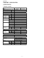
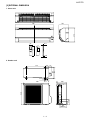
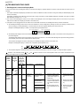
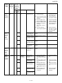
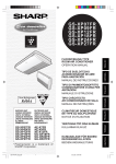
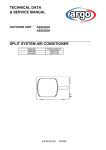
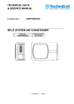
AYXP7FR
SERVICE MANUAL
S6512AYXP7FR/T
SPLIT TYPE
ROOM AIR CONDITIONER
INDOOR UNIT
MODELS
OUTDOOR UNIT
AY-XP7FR AE-X7FR
AY-XP9FR AE-X9FR
AY-XP12FR AE-X12FR
In the interests of user-safety (Required by safety regulations in some countries) the set should
be restored to its original condition and only parts identical to those specified should be used.
CONTENTS
CHAPTER 1. SPECIFICATION
[1] SPECIFICATION............................................ 1-1
[2] EXTERNAL DIMENSION............................... 1-4
[3] WIRING DIAGRM .......................................... 1-5
[4] ELECTRICAL PARTS .................................... 1-6
[5]
[6]
CHAPTER 2. EXPLAMATION OF CIRCUIT AND OPERATION
[1] BLOCK DIAGRAMS....................................... 2-1
[2] MICROCOMPUTER CONTROL SYSTEM
........ 2-3
[3] FUNCTION..................................................... 2-8
CHAPTER 4. REFRIGERATION CYCLE
[1] FLOW FOW REFRIGERANT ........................4-1
[2] STANDARD CONDITION ..............................4-1
[3] TEMPERATURE AT EACH PART AND
PRESSURE IN 3-WAY VALVE ......................4-1
[4] PERFORMANCE CURVES...........................4-2
CHAPTER 3. FUNCTION AND OPERATION OF PROTECTIVE PROCEDURES
[1] PROTECTION DEVICE FUNCTIONS AND
OPERATIONS................................................ 3-1
[2] AIR CONDITIONER OPERATION IN
THERMISTOR ERROR ................................. 3-3
[3] THERMISTOR TEMPERATURE CHARACTERISTICS ............................................... 3-5
[4] HOW TO OPERATE THE OUTDOOR
UNIT INDEPENDENTLY................................ 3-6
Parts marked with "
[7]
[8]
GENERAL TROUBLESHOOTING CHART
........3-6
MALFUNCTION (PARTS) CHECK METHOD .................................................................3-8
OUTDOOR UNIT CHECK METHOD...........3-10
TROUBLESHOOTING GUIDE ....................3-13
CHAPTER 5. DISASSEMBLING PROCEDURE
[1] DISASSEMBLY OF INDOOR UNIT...............5-1
[2] DISASSEMBLY OF OUTDOOR UNIT...........5-7
REPLACEMENT PARTS LIST
" are important for maintaining the safety of the set. Be sure to replace these parts with specified ones for
maintaining the safety and performance of the set.
SHARP CORPORATION
This document has been published to be used
for after sales service only.
The contents are subject to change without notice.
AYXP7FR
Service Manual
AYXP7FR
CHAPTER 1. SPECIFICATION
[1] SPECIFICATION
1. AY-XP7FR – AE-X7FR
MODEL
ITEMS
Cooling capacity(Min. > Max.)
Heating capacity(Min. > Max.)
Moisture removal(at cooling)
kW
kW
Liters/h
INDOOR UNIT
AY-XP7FR
2.1 (0.9 - 2.5)
2.4 (0.9 - 3.4)
OUTDOOR UNIT
AE-X7FR
Electrical data
Phase
Rated frequency
Rated voltage
Rated current ✩
(Min - Max.)
Rated input ✩
(Min - Max.)
Power factor ✩
Compressor
Refrigerant system
Noise level
(at cooling)
Hz
V
A
A
W
W
%
%
Cool
Heat
Cool
Heat
Cool
Heat
Type
Model
Oil charge
Evaporator
Condenser
Control
Refrigerant (R410A)
De-lce system
High
dB(A)
Low
dB(A)
Soft
dB(A)
Single
50
230
2.5 (1.0 - 4.1)
2.4 (0.9 - 4.5)
530 (200 - 760)
510 (160 - 1100)
92
92
Hermetically sealed rotary type
DA89X1F-23F
370cc (VG74)
Louver Fin and Grooved tube type
Corrugate Fin and Grooved tube type
Expansion valve
830g
Micro computer controled reversed systems
37
45
–
–
28
–
Fan system
Drive
Air flow quantity
(at cooling)
High
Low
Soft
m3/min.
m3/min.
m3/min.
Fan
Direct drive
8.0
6.8
5.5
Cross flow fan
23.2
–
–
Propeller fan
Connections
Refrigerant coupling
Refrigerant tube size Gas, Liquid
Drain piping mm
Flare type
3/8", 1/4"
O.D φ18
Others
Safety device
Air filters
Net dimensions
Net weight
Width
Height
Depth
mm
mm
mm
kg
Compressor: Thermal protector
Fan motors: Thermal fuse
Fuse, Micro computer control
Polypropylene net (Washable)
790
730
278
540
198
250
10
33
1–1
AYXP7FR
2. AY-XP9FR – AE-X9FR
MODEL
ITEMS
Cooling capacity(Min. > Max.)
Heating capacity(Min. > Max.)
Moisture removal(at cooling)
kW
kW
Liters/h
INDOOR UNIT
AY-XP9FR
2.64 (0.9 - 3.0)
3.1 (0.9 - 4.8)
OUTDOOR UNIT
AE-X9FR
Electrical data
Phase
Rated frequency
Rated voltage
Rated current ✩
(Min - Max.)
Rated input ✩
(Min - Max.)
Power factor ✩
Compressor
Refrigerant system
Noise level
(at cooling)
Hz
V
A
A
W
W
%
%
Cool
Heat
Cool
Heat
Cool
Heat
Type
Model
Oil charge
Evaporator
Condenser
Control
Refrigerant (R410A)
De-lce system
High
dB(A)
Low
dB(A)
Soft
dB(A)
Single
50
230
3.7 (1.0 - 4.8)
3.5 (0.9 - 6.1)
780 (200 - 960)
730 (160 - 1400)
92
91
Hermetically sealed rotary type
DA89X1F-23F
370cc (VG74)
Louver Fin and Grooved tube type
Corrugate Fin and Grooved tube type
Expansion valve
830g
Micro computer controled reversed systems
39
45
–
–
28
–
Fan system
Drive
Air flow quantity
(at cooling)
High
Low
Soft
m3/min.
m3/min.
m3/min.
Fan
Direct drive
8.6
7.3
5.5
Cross flow fan
23.3
–
–
Propeller fan
Connections
Refrigerant coupling
Refrigerant tube size Gas, Liquid
Drain piping mm
Flare type
3/8", 1/4"
O.D φ18
Others
Safety device
Air filters
Net dimensions
Net weight
Width
Height
Depth
mm
mm
mm
kg
Compressor: Thermal protector
Fan motors: Thermal fuse
Fuse, Micro computer control
Polypropylene net (Washable)
790
730
278
540
198
250
10
33
1–2
AYXP7FR
3. AY-XP12FR – AE-X12FR
MODEL
ITEMS
Cooling capacity(Min. > Max.)
Heating capacity(Min. > Max.)
Moisture removal(at cooling)
kW
kW
Liters/h
INDOOR UNIT
AY-XP12FR
3.5 (0.9 - 3.8)
4.0 (0.9 - 6.0)
OUTDOOR UNIT
AE-X12FR
Electrical data
Phase
Rated frequency
Rated voltage
Rated current ✩
(Min - Max.)
Rated input ✩
(Min - Max.)
Power factor ✩
Compressor
Refrigerant system
Noise level
(at cooling)
Hz
V
A
A
W
W
%
%
Cool
Heat
Cool
Heat
Cool
Heat
Type
Model
Oil charge
Evaporator
Condenser
Control
Refrigerant (R410A)
De-lce system
High
dB(A)
Low
dB(A)
Soft
dB(A)
Single
50
230
5.0 (1.1 - 8.2)
4.8 (1.0 - 8.0)
1090 (210 - 1300)
1030 (180 - 1900)
95
93
Hermetically sealed rotary type
5RS102XBE01
320cc (RB68A or Freol Alpha 68M)
Louver Fin and Grooved tube type
Corrugate Fin and Grooved tube type
Expansion valve
1030g
Micro computer controled reversed systems
40
48
–
–
28
–
Fan system
Drive
Air flow quantity
(at cooling)
High
Low
Soft
m3/min.
m3/min.
m3/min.
Fan
Direct drive
9.8
8.5
6.9
Cross flow fan
26.7
–
–
Propeller fan
Connections
Refrigerant coupling
Refrigerant tube size Gas, Liquid
Drain piping mm
Flare type
3/8", 1/4"
O.D φ18
Others
Safety device
Air filters
Net dimensions
Net weight
Width
Height
Depth
mm
mm
mm
kg
Compressor: Thermal protector
Fan motors: Thermal fuse
Fuse, Micro computer control
Polypropylene net (Washable)
790
730
278
540
198
250
10
37
NOTE: The condition of star”✩” marked item are ‘ISO5151’ : 1994(E), contition T1.
1–3
AYXP7FR
[2] EXTERNAL DIMENSION
1. Indoor unit
198
278
790
18.5
58
175
INVERTER AIR CONDITIONER
22.0
2. Outdoor unit
135
72
299
324
515
37.5 12
4.
14
250
81
136
540
5
58
730
165
167.5
1–4
AYXP7FR
[3] WIRING DIAGRM
1. Indooa unit
2. Outdooa unit
2.1. AE-X7FR / AE-X9FR
420V 420V
750μF 750μF
2.2. AE-X12FR
1–5
AYXP7FR
[8] TROUBLESHOOTING GUIDE
1. Self-Diagnosis Function and Display Mode
To call out the content of the self-diagnosis memory, hold down the emergency operation button for more than 5 seconds when the indoor unit is not
operating.
•
The number of indications displayed by the LEDs on the outdoor unit differs from that for the 2001 cooling unit models (for detailed display of malfunction information).
The display of malfunction No. differs from that of the 2001 cooling unit models. To show detailed malfunction information, two types of numbers
flash alternately. (example: "21" ←→ "-0")
1) The content of the self-diagnosis memory can be called out and displayed on the seven-segment display section on the indoor unit. (The error
data cannot be called out for display by the LED on the outdoor unit.)
2) If the power cord is unplugged from the AC outlet or the circuit breaker is turned off, the self-diagnosis memory loses the stored data.
a) The self-diagnosis display function of the indoor unit indicates the content of diagnosis by showing the error main category (number) and the
error sub-category (-number) alternately in 1-second intervals on the seven-segment display section of the indoor unit.
Example of self-diagnosis display on indoor unit: Compressor high-temperature error
'TTQTOCKPECVGIQT[
'TTQTUWDECVGIQT[
b) The self-diagnosis display function of the outdoor unit indicates the error information by flashing LED1 on the outdoor unit according to the content of self-diagnosis.
The self-diagnosis display function of the outdoor unit is active only for about 3 to 10 minutes after self-diagnosis is performed during operation,
and the display returns to normal condition after this display period.
The content of self-diagnosis cannot be called out by the self-diagnosis display function of the outdoor unit.
Example of self-diagnosis display on outdoor unit: Compressor high-temperature error
ON
OFF
1 sec 1 sec 0.6 sec 1 sec 0.6 sec 1 sec 1 sec 1 sec 0.6 sec 1 sec 0.6 sec 1 sec 1 sec
c) The content of diagnosis is transferred to the indoor unit via serial communication, but it does not trigger a complete shutdown operation.
: Flashes in 2-sec intervals (normal), : On,
intervals, the outdoor unit is in normal condition.)
Status of
indoor/
outdoor
units
Indoor/
outdoor
units in
operation
Indoor/
outdoor
units in
complete
shutdown
Indication
by LED1
on outdoor unit
*2
Normal
flashing
1 time
Malfunction
No. displayed on
main unit
display section *1
Main Subcate- category gory
0
0
1
: Off,
: Flashes 3 times in 0.2-sec intervals (When LED1 on the outdoor unit flashes in 2-sec
Content of diagnosis
Main category
Inspection location/method
Remedy
–
–
Sub-category
Normal
Heat exchanger
thermistor short-circuit error
(1)
-1
Outside temperature thermistor
short-circuit error
(2)
-2
Suction thermistor
short-circuit error
2-way valve thermistor short-circuit
error
(3)
-0
-3
Outdoor unit
thermistor
short-circuit
3 – 13
Measure resistance of the
outdoor unit thermistors.
(TH2 to TH5: Approx. 4.4
kΩ at 25°C)
Check the lead wire of the
outdoor unit thermistor for
torn sheath and short-circuit.
No abnormality found in
above inspections (1) and
(2).
(1)
Replace the outdoor
unit thermistor assembly.
(2)
Replace the outdoor
unit thermistor assembly.
(3)
Replace the outdoor
unit control PWB
assembly.
AYXP7FR
Status of
indoor/
outdoor
units
Indoor/
outdoor
units in
complete
shutdown
Indication
by LED1
on outdoor unit
*2
2 times
Malfunction
No. displayed on
main unit
display section *1
Main Subcate- category gory
2
-0
Content of diagnosis
Main category
Sub-category
Cycle temperature
Compressor hightemperature error
Inspection location/method
(1)
Check the outdoor unit air
outlet for blockage.
(1)
(2)
Check if the power supply
voltage is 90 V or higher at
full power.
Check the pipe connections for refrigerant leaks.
Measure resistance of the
outdoor unit compressor
thermistor.
(TH1: Approx. 53 kΩ at
25°C)
Check the expansion
valve for proper operation.
(2)
(3)
(4)
(5)
-1
Indoor
unit in
operation
Outdoor
unit in
temporary stop
-2
-3
-4
Indoor
unit in
operation
Outdoor
unit in
temporary stop
Indoor/
outdoor
units in
complete
shutdown
3 times
3
-0
Dry operation
5 times
5
-0
Outdoor unit
thermistor
open-circuit
-1
-2
-3
-4
Temporary stop due
to compressor discharge overheat *3
Temporary stop due
to outdoor unit heat
exchanger overheat
*3
Temporary stop due
to outdoor unit heat
exchanger overheat
*3
Temporary stop due
to 2-way valve
freeze *3
Temporary stop due
to dehumidifying
operation *3
(Temporary stop for cycle protection)
Heat exchanger
thermistor open-circuit error
(1)
Outside temperature thermistor
open-circuit error
Suction thermistor
open-circuit error
(2)
2-way valve thermistor open-circuit
error
Discharge thermistor open-circuit
error
(4)
3 – 14
Remedy
(3)
(4)
(5)
Ensure unobstructed
air flow from the outdoor unit air outlet.
Connect power supply of proper voltage.
Charge the specified
amount of refrigerant.
Replace the outdoor
unit compressor thermistor assembly.
Replace the expansion valve coil, expansion valve or outdoor
unit control PWB
assembly.
–
(Temporary stop for cycle protection)
–
(Temporary stop for cycle protection)
–
(Temporary stop for cycle protection)
–
(Temporary stop for cycle protection)
–
(3)
Check connector CN8 of
the outdoor unit thermistor for secure installation.
Measure resistance of outdoor thermistors TH1 to
TH5.
Check the lead wires of
thermistors TH1 through
TH5 on the outdoor unit
control PWB for open-circuit.
No abnormality found in
above inspections (1)
through (3).
(1)
Correct the installation.
(2)
Replace the outdoor
unit thermistor assembly.
Replace the outdoor
unit thermistor assembly.
(3)
(5)
Replace the outdoor
unit control PWB
assembly.
AYXP7FR
Status of
indoor/
outdoor
units
Indoor/
outdoor
units in
complete
shutdown
Indication
by LED1
on outdoor unit
*2
6 times
Malfunction
No. displayed on
main unit
display section *1
Main Subcate- category gory
6
-0
Content of diagnosis
Main category
Sub-category
Outdoor unit DC
DC overcurrent error
Inspection location/method
(1)
IPM continuity check
(1)
(2)
Check the IPM and heat
sink for secure installation.
(2)
(3)
Check the outdoor unit fan
motor for proper rotation.
No abnormality found in
above inspections (1)
through (3).
No abnormality found in
above inspections (1)
through (4).
Check the IPM is attached
correctly to the outdoor
unit control PWB.
Check the outdoor unit air
outlet for blockage.
(3)
Check the outdoor unit fan
for proper rotation.
IPM continuity check
(2)
(4)
(5)
-1
Indoor/
outdoor
units in
complete
shutdown
7 times
7
-0
IPM pin level error
Outdoor unit AC
AC overcurrent error
(1)
(2)
(1)
(1)
-2
AC maximum current error
(1)
Check the outdoor unit air
outlet for blockage.
(1)
(2)
Check the outdoor unit fan
for proper rotation.
Check if there is an opencircuit in the secondary
winding of the current
transformer of the outdoor
unit control PWB.
Check if the refrigerant
volume is abnormally low.
Check if the refrigerant
flows properly.
(1)
Check to make sure outdoor unit thermistor TH2
(heat exchanger) and TH5
(2-way valve) are installed
in correct positions.
Measure resistance of
thermistors TH1 and TH5.
Check the 4-way valve for
proper operation.
No abnormality found in
above inspections (1)
through (3).
Check if the refrigerant
volume is abnormally low.
Check the 4-way valve for
proper operation.
check to see compressor
type is correct.
(1)
AC current deficiency error
(1)
(3)
9
(5)
AC overcurrent error
in OFF status
(2)
9 times
(4)
-1
-3
Indoor/
outdoor
units in
complete
shutdown
Remedy
-0
Outdoor unit
cooling/heating
switchover
Thermistor installation error or 4-way
valve error
(1)
(2)
(3)
(4)
-3
Torque control error
(1)
(2)
(3)
3 – 15
(1)
(1)
(2)
(3)
(2)
(3)
(4)
(1)
(2)
(3)
Replace the outdoor
unit control PWB
assembly.
Correct the installation (tighten the
screws).
Replace the outdoor
unit fan motor.
Replace the outdoor
unit control PWB
assembly.
Replace the compressor.
Replace the outdoor
unit control PWB
assembly.
Ensure unobstructed
air flow from the outdoor unit air outlet.
Check the outdoor unit
fan motor.
Replace the outdoor
unit control PWB
assembly.
Ensure unobstructed
air flow from the outdoor unit air outlet.
Check the outdoor unit
fan motor.
Replace the outdoor
unit control PWB
assembly.
Charge the specified
amount of refrigerant.
Correct refrigerant
clogs.
(2-way valve, 3-way
valve, pipe, expansion valve)
Correct the installation.
Replace the thermistor assembly.
Replace the 4-way
valve.
Replace the outdoor
unit control PWB
assembly.
Change the specified
amount of refrigerant.
Replace the 4-way
valve.
Replace the compressor with the correct
part.
AYXP7FR
Status of
indoor/
outdoor
units
Indoor/
outdoor
units in
complete
shutdown
Indoor/
outdoor
units in
complete
shutdown
Indication
by LED1
on outdoor unit
*2
11
times
Malfunction
No. displayed on
main unit
display section *1
Main Subcate- category gory
11
-0
Content of diagnosis
Main category
Sub-category
Outdoor unit DC
fan
Outdoor unit DC fan
rotation error
Inspection location/method
(1)
13
-0
DC compressor
-1
Indoor/
outdoor
units in
operation
Indoor
unit in
operation
Outdoor
unit in
complete
shutdown
14
times
14
-0
Outdoor unit
PAM
-1
17
-0
Wires between
units
(2)
Replace the outdoor
unit fan motor.
Replace the outdoor
unit control PWB
assembly.
Replace the outdoor
unit control PWB
assembly.
Correct the installation.
(U: Red, V: White, W:
Orange)
(3)
(4)
Outdoor unit control PWB
(4)
Compressor startup
error
(1)
(1)
Compressor rotation error
(120° energizing
error)
(2)
Check the colors (red,
white, orange) of the compressor cords for proper
connection. (PWB side,
compressor side)
Check if the IPM terminal
resistance values are uniform.
No abnormality found in
above inspections (1) and
(2).
No abnormality found in
above inspections (1)
through (3).
Check the AC power supply voltage for fluctuation.
No abnormality found in
above inspection (1).
(3)
(2)
(3)
(4)
PAM over voltage
error
Compressor rotation error
(1)
PAM clock error
(1)
Check the PAM clock for
proper input.
(1)
Serial open-circuit
(1)
Check the wires between
units.
Check voltage between
Nos. 1 and 2 on the
indoor/outdoor unit terminal boards.
Check the wires between
units.
Check the outdoor unit
fuse.
(1)
Check 15-V, 13-V and 5-V
voltages on the PWB.
Check resistance between
IPM terminals.
Check pins No. 5 and 7 of
connector CN3 of the outdoor unit fan motor for
short-circuit.
Outdoor unit control PCB
(3)
(2)
(2)
Outdoor unit does
not turn on due to
erroneous wiring
(1)
(2)
(3)
(4)
(5)
18
Correct the installation.
(3)
(4)
Indoor/
outdoor
units in
complete
shutdown
(1)
Check connector CN3 of
the outdoor unit DC fan
motor for secure installation.
Check the outdoor unit fan
motor for proper rotation.
Check fuse FU3.
(2)
13
times
Remedy
-0
Serial short-circuit
(1)
-1
Serial erroneous wiring
(1)
3 – 16
Check the wires between
units.
Check the wires between
units.
(1)
(2)
Replace the outdoor
unit control PWB
assembly.
Replace the outdoor
unit control PWB
assembly.
Replace the compressor.
Connect stable power
supply.
Replace the outdoor
unit control PWB
assembly.
Replace the outdoor
unit control PWB
assembly.
(2)
Connect stable power
supply.
Replace the outdoor
unit control PCB
assembly.
(1)
Correct the wiring.
(2)
Replace the fuse/outdoor unit control PCB
assembly.
Replace the outdoor
unit control PCB
assembly.
(4)
Replace the outdoor
unit fan motor.
(5)
(1)
Replace the outdoor
unit control PCB
board.
Correct the wiring.
(1)
Correct the wiring.
AYXP7FR
Status of
indoor/
outdoor
units
Indoor/
outdoor
units in
complete
shutdown
Indication
by LED1
on outdoor unit
*2
Malfunction
No. displayed on
main unit
display section *1
Main Subcate- category gory
19
-0
Content of diagnosis
Main category
Indoor unit fan
Inspection location/method
Sub-category
Indoor unit fan error
(1)
(2)
(3)
(4)
Indoor/
outdoor
units in
operation
Indoor/
outdoor
units in
operation
20
88
-0
Remedy
Indoor unit control PCB
EEPROM data error
Control and display PCB
Communication
error
(1)
(2)
3 – 17
Check the indoor fan
motor for proper rotating
operation.(Check fan
lock.)
Check the lead wire of the
indoor fan motor for opencircuit.
Check CN1 of the indoor
unit fan motor for secure
installation.
No abnormality found in
above inspections (1)
through (3).
(EEPROM read data
error)
(1)
Replace the indoor fan
motor.
(2)
Replace the indoor fan
motor.
(3)
Correct the installation of CN1 of the
indoor fan motor.
Replace the indoor
unit control PWB.
Check for disconnected
connector between control
PCB and display PCB,
and open-circuit in lead
wires.
Check that control PCB
outputs signals correctly.
(1)
Insert connectors correctly, or replace control PWB.
(2)
Replace control PWB.
(4)
Replace the indoor
unit control PWB.
AYXP7FR
Malfunction indications due to erroneous wiring during air conditioner installation
Inter-unit wiring error mode
1
Indoor unit relay
Malfunction diagnosis display
1
Indoor
unit N
N
2
2
Symptom
Turns On momentarily, then turns Off.
"18-1"
1
Outdoor
unit
2
1
Indoor
unit N
N
2
2
Indoor unit relay
Malfunction diagnosis display
Relays turns Off after about 30 minutes.
None
(Displays "18-0" when malfunction code is called out.)
Indoor unit relay
Malfunction diagnosis display
Relays turns Off after about 30 minutes.
None
(Displays "18-0" when malfunction code is called out.)
Indoor unit relay
Malfunction diagnosis display
Turns On momentarily, then turns Off.
"18-1"
Indoor unit relay
Malfunction diagnosis display
Turns On momentarily, then turns Off.
"18-1"
1
Outdoor
unit
3
1
Indoor
unit N
1
N
2
2
Outdoor
unit
4
1
Indoor
unit N
1
N
2
2
Outdoor
unit
5
1
Indoor
unit N
N
2
2
1
Outdoor
unit
3 – 18
AYXP7FR
[4] PERFORMANCE CURVES
NOTE
1) Indoor fan speed: Hi
2) Vertical adjustment louver "45°”, Horizontal adjustment louver "front"
3) Indoor air temp. : Cooling 27°C, Heating 20°C
4) Power source : 230V, 50Hz
1. AY-XP7FR
1.1. At Cooling
1.2. At Heating
600
Input(W)
Input(W)
600
500
400
500
400
Heating capacity(kW)
Cooling capacity(kW)
300
2.6
2.4
2.2
2.0
25
30
35
Outside air temp.(ºC)
3.0
2.5
2.0
1.5
40
-5
0
5
7
Outside air temp.(ºC)
10
2. AY-XP9FR
2.1. At Cooling
2.2. At Heating
800
Input(W)
Input(W)
900
800
700
700
600
Heating capacity(kW)
Cooling capacity(kW)
600
3.2
3.0
2.8
2.6
2.4
25
30
35
Outside air temp.(ºC)
3.5
3.0
2.5
2.0
-5
40
4–2
0
5
7
Outside air temp.(ºC)
10
AYXP7FR
3. AY-XP12FR
3.1. At Cooling
3.2. At Heating
1200
1100
Input(W)
Input(W)
1200
1100
1000
900
800
Heating capacity(kW)
Cooling capacity(kW)
900
1000
4.0
3.8
3.6
3.4
3.2
25
30
35
Outside air temp.(ºC)
40
4.5
4.0
3.5
3.0
2.5
-5
4–3
0
5
7
Outside air temp.(ºC)
10