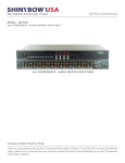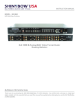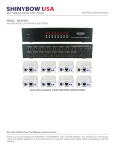
1
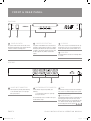
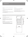
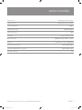
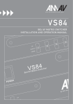
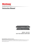
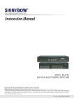
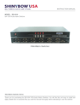
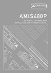
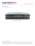
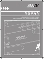
VGA44
4 X 4 VG A M AT R I X S W I TCHER
I N S TA L L AT I O N A N D O P E R AT I O N M ANUAL
r
4
4
A
VG
G
4x4 V
VGA44 manual.indd
1
er
witch
S
x
i
r
t
A Ma
12/3/07
2:24:58 PM
I M P O RTANT SAFETY INFORMATION
13.
Do not block fan intake or exhaust ports. Do not operate equipment on a surface or in an environment which may impede the normal flow
of air around the unit, such as a bed, rug, weathersheet, carpet, or completely enclosed rack. If the unit is used in an extremely dusty
or smoky environment, the unit should be periodically “blown free” of foreign matter.
1.
Save the carton and packing material even if the equipment has arrived in good condition. Should you ever need to ship the unit, use
only the original factory packing.
2.
Read all documentation before operating your equipment. Retain all documentation for future reference.
3.
Follow all instructions printed on unit chassis for proper operation.
4.
Do not spill water or other liquids into or on the unit, or operate the unit while standing in liquid.
5.
Make sure power outlets conform to the power requirements listed on the back of the unit.
6.
Do not use the unit if the electrical power cord is frayed or broken.
The power supply cords should be routed so that they are not likely to be walked on or pinched by items placed upon or against them, paying particular attention to cords and plugs, convenience receptacles, and the point where they exit from the appliance.
7.
Always operate the unit with the AC ground wire connected to the
electrical system ground. Precautions should be taken so that the
means of grounding of a piece of equipment is not defeated.
8.
Mains voltage must be correct and the same as that printed on the
rear of the unit. Damage caused by connection to improper AC voltage
is not covered by any warranty.
19. Non-use periods. The power cord of equipment should be unplugged
from the outlet when left unused for a long period of time.
9.
Have gain controls on amplifiers turned down during power-up to prevent speaker damage if there are high signal levels at the inputs.
20. Service Information Equipment should be serviced by qualified service
personnel when:
10 Power down & disconnect units from mains voltage before making
connections.
14. Do not remove the cover. Removing the cover will expose you to potentially dangerous voltages. There are no user serviceable parts inside.
15. Do not drive the inputs with a signal level greater than that required to drive equipment to full output.
16. Do not connect the inputs / outputs of amplifiers or consoles to any
other voltage source, such as a battery, mains source, or power supply,
regardless of whether the amplifier or console is turned on or off.
17.
Do not run the output of any amplifier channel back into another channel’s input. Do not parallel- or series-connect an amplifier output
with any other amplifier output. Australian Monitor Inc is not responsible for damage to loudspeakers for any reason.
18. Do not ground any red (“hot”) terminal. Never connect a “hot” (red)
output to ground or to another “hot” (red) output!
A. The power supply cord or the plug has been damaged.
B. Objects have fallen, or liquid has been spilled into the equipment
11. Never hold a power switch in the “ON” position if it won’t stay there itself!
C. The equipment has been exposed to rain
12. Do not use the unit near stoves, heat registers, radiators, or other heat
producing devices.
D. The equipment does not appear to operate normally, or exhibits a marked
change in performance
E. The equipment has been dropped, or the enclosure damaged.
THIS SAFETY INFORMATION IS OF A GENERAL NATURE AND MAY BE SUPERSEDED BY INSTRUCTIONS CONTAINED WITHIN THIS MANUAL
VGA44 manual.indd
2
12/3/07
2:24:58 PM
INTRODUCTION AND CONTENTS
The AMAV VGA44 is an 4x4 VGA Matrix Switcher, supporting resolutions
of up to 2048x2048. Designed for the demanding commercial audio-visual
market, the VGA44 provides comprehensive video switching in an elegant,
rack-mount package. The VGA44 provides four VGA video input sources and
four VGA video destination outputs each featuring a 15 pin high density
D connector. Any input source is routable to any combination of outputs;
controllable by either front panel control, IR remote control or RS232 serial
control. The VGA44 offers the flexibility and features demanded by any
quality AV application.
INTRODUCTION
3
FRONT & REAR PANEL
4
ADVANCED FEATURES
6
OPERATION
7
SPECIFICATIONS 8
AUS, EUR, USA
Copyright 23 Feb 2007
This symbol is intended to alert the user to the presence
of uninsulated “dangerous voltage” within the products
enclosure that may be of sufficient magnitude to constitute
a risk of electric shock to persons.
CAUTION
RISK OF ELECTRIC SHOCK
DO NOT OPEN
CAUTION: TO REDUCE THE RISK OF ELECTRIC SHOCK,
This symbol is intended to alert the user to the presence
of important operational and maintenance (servicing)
instructions in the literature accompanying the appliance.
DO NOT REMOVE COVER (OR BACK),
NO USER SERVICEABLE PARTS INSIDE,
REFER SERVICING TO QUALIFIED SERVICE PERSONAL.
Caution:
WARNING!
TO REDUCE THE RISK OF FIRE OR ELECTRIC SHOCK
To prevent electric shock do not use this (polarised) plug
with an extension cord, receptacle or other outlet unless
the blades can be fully inserted to prevent blade exposure.
To prevent electric shock, match wide blade of plug to wide
slot, fully insert.
DO NOT EXPOSE THIS EQUIPMENT TO RAIN OR MOISTURE.
V G A 4 4 I N S TA L L AT I O N & O P E R AT I O N M A N U A L
VGA44 manual.indd
3
PA G E 3
12/3/07
2:24:58 PM
F R O N T & R E A R PA N E L
FRONT PANEL
VGA44
4x4 VGA Matrix Switcher
4
1
1
3
Power ON Switch
This power switch turns the unit on and off. The
inbuilt LED will illuminate red to indicate that the
switcher is ON and is receiving power
2
2
4
Source Select Buttons
3
A separate UP and DOWN source select button is
provided for each destination output. A 7 segment
LED display will indicate the input source number
assigned to a destination output. Any input source
can be assigned to any number of destination
outputs
IR Sensor
The IR sensor receives IR commands from the supplied remote control. To use the supplied remote
control, point the remote control at the IR sensor
4
Rack Ears
The VGA44 features rack ears for mounting within
a 19” Rack
REAR PANEL
3
4
OUTPUT
2
1
3
2
4
1
INPUT
2
1
3
4
1 Source Input Connectors
2 Destination Output Connector
3 RS232
Four source inputs are provided, each featuring: • One VGA video input on a 15 pin high density D connector
Four destination outputs are provided, each featuring: • One VGA video output on a 15 pin high density D connector
The selected input source is routed to the respective destination output.
Serial RS232 control port to allow for interfacing to
a PC, Crestron or similar third party control system
PA G E 4
VGA44 manual.indd
4 DC Power Inlet
The VGA44 VGA matrix switcher is fitted with a DC
power plug-pack input connector. Please ensure
that the plug-pack used is of an approved type and
is of sufficient current carrying capacity with the
correct voltage and connector polarity
V G A 4 4 I N S TA L L AT I O N & O P E R AT I O N M A N U A L
4
12/3/07
2:24:59 PM
A D VA N C E D F E AT U R E S
RS232
Front Panel Lock
The AMAV switcher can be controlled via the RS232 serial control port to
allow for interfacing to a PC, Crestron or similar third party control system.
The serial communication parameters are 9600 baud, 8 bit, No Parity and 1
stop bit – this is often referred to as 9600 8N1. When the unit recognises
a complete command it will perform the requested action – there is no
delimiter character required.
The unit does not send out a message when a value is changed from the
front panel or by IR control. If the unit needs to be controlled from the front
panel in addition to the RS232 control, you would need to regularly poll the
units’ status to ensure the control system accurately reflected the current
settings.
.
Note : Hard resetting the unit will unlock the Front Panel controls.
SBSYSMLK - When front panel is locked, changes can only be made by RS232
SBSYSMUK - Front Panel Unlock
Unit will respond with
SBSYSLOK
- Front Panel has been Locked
SBSYSULK
- Front Panel has been Unlocked
Example : Lock Front Panel Buttons
- Send
- Rcvd
SBSYSMLK
SBSYSLOK
Unit Reset
Commands
To Switch Inputs to Outputs
SBIøXOøY
Where X is Output Number (1-4) and Y is Input Number (1-4)
Unit will respond with
Where X is Output Number (1-4) and Y is Input Number (1-4)
SBUDøXOY Example : Send Input 1 to Output 4
- Send
- Rcvd
SBSYSMLK - Reset every output to Input 1
Unit will respond with
SBRSTACK - Unit has reset each Output to Input 1
Example : Reset all outputs to Input 1
- Send
- Rcvd
SBALLRST
SBRSTACK
SBIø1Oø4
SBUDø1O4
Standby Mode
Note : Turning the unit System Power Off over RS232 will blank the displays leaving only the Power Switch LED on. Hard resetting the unit when in System Power Off mode will return the unit to normal operation and unlock the front panel.
Even while the unit is turned off by RS232 it will continue to accept and act
upon switching commands. This allows you to set up a ‘scene’ before soft
powering on the unit and enabling the video outputs. The unit will still return
status and change messages in response to commands sent while in System
Power Off mode.
SBSYSMON SBSYSMOF - Put system into Standby (Soft Power Off)
- Bring unit out of Standby (Soft Power On)
Unit will respond with
- Unit is in Standby
- Unit is no longer in Standby
SBALOFAK
SBALONAK
Example : Put Unit in Standby (Soft Power)
SBSYSMOF
- Send SBALOFAK
- Rcvd
V G A 4 4 I N S TA L L AT I O N & O P E R AT I O N M A N U A L
VGA44 manual.indd
5
PA G E 5
12/3/07
2:24:59 PM
O P E R AT I O N
Before making any connections to the VGA44, observe the
following:
> Before making any connections to the VGA44, observe the following:
> Ensure the mains voltage supply matches the label on the supplied plug-pack (+/- 10%)
> Ensure that the power switch is OFF
> Ensure that all system grounds (earth) are connected to a common point.
Avoid powering equipment within a system from multiple power sources that
may be separated by large distances
Operation
> Connect all audio video sources and destination equipment
> Power up all source and destination audio-visual sources
> Power up the VGA44 VGA matrix switcher
> For each destination output select the appropriate input source by using
the front panel UP and DOWN select button, the supplied IR remote control,
or through the RS232 serial communications port
Remote Control
The AMAV VGA44 matrix switcher ships with a remote control. The
remote control has the following functionality:
i) Source Select Buttons
Four separate input assignment buttons are provided for each of the
four VGA outputs. The last selected input source will be routed to
the destination output. Input sources may be assigned to multiple
destination outputs
ii) Power Button
Toggles the unit into, and out of, standby mode. In standby mode the
matrix switcher will stop video routing. Standby mode is indicated by
the illumination of the front panel power LED only.
POWER
ii
Output - 1
INPUT-1
INPUT-2
INPUT-3
INPUT-4
INPUT-2
INPUT-3
INPUT-4
INPUT-2
INPUT-3
INPUT-4
INPUT-2
INPUT-3
INPUT-4
Output - 2
INPUT-1
i
Output - 3
INPUT-1
Output - 4
INPUT-1
VGA44
4x4 VGA Matrix Switcher
PA G E 6
VGA44 manual.indd
V G A 4 4 I N S TA L L AT I O N & O P E R AT I O N M A N U A L
6
12/3/07
2:24:59 PM
S P E C I F I C AT I O N S
Video Inputs 4x VGA video (HD-15 pin connectors)
Video Outputs
4x VGA video (HD-15 pin connectors)
Video Bandwidth
>450MHz
Video Resolution
2048x2048 Maximum
Video Crosstalk
Control
>60dB
Front Panel, IR Remote, RS232
RS232 Control
Power
9600 Baud, No Parity, 8 data bits, 1 stop bit
+12V DC, centre +ve, outer –ve, 450mA Max
Dimension (H x W x D)
44mm x 440mm x 200mm
SHIPPING DimensionS (H x W x D)
98mm x 510mm x 283mm
Shipping Weight V G A 4 4 I N S TA L L AT I O N & O P E R AT I O N M A N U A L
VGA44 manual.indd
7
2.2 kg
PA G E 7
12/3/07
2:25:00 PM
AUSTRALIA AND NEW ZEALAND
w w w. a u s t r a l i a n m o n i t o r. c o m . a u
SYDNEY
MELBOURNE
BRISBANE
ADELAIDE
PERTH
AUCKLAND
(NSW & ACT SALES)
(VIC & TAS SALES)
(QLD SALES)
(SA & NT SALES)
(WA SALES)
(NZ SALES)
1 Clyde Street
Silverwater
NSW 2128
Private Bag 149
Silverwater NSW 1811
Phone: (02) 9647 1411
Fax: (02) 9648 3698
Email:
[email protected]
22/277
Middleborough Road
Box Hill VIC 3128
PO Box 151 Blackburn
South VIC 3130
Phone: (03) 9890 7477
Fax: (03) 9890 7977
Email:
[email protected]
42 Commercial Road
Fortitude Valley
QLD 4006
PO Box 871 Fortitude
Valley QLD 4006
Phone: (07) 3852 1312
Fax: (07) 3252 1237
Email:
[email protected]
31 Walsh Street
Thebarton
SA 5031
PO Box 157
Hindmarsh SA 5007
Phone: (08) 8352 4444
Fax: (08) 8352 4488
Email:
[email protected]
3/11 Howe Street
Osborne Park WA 6017
PO Box 1281
Osborne Park BC
WA 6916
Phone: (08) 9228 4222
Fax: (08) 9228 4233
Email:
[email protected]
9C Piermark Drive
Albany 0752
New Zealand
PO Box 300-512
Albany 0752
Phone: (09) 415 9426
Fax: (09) 415 9864
Email:
[email protected]
EUROPE / ASIA / MIDDLE EAST
USA / SOUTH AMERICA
INTERNATIONAL SALES
SENNHEISER ELECTRONIC CORPORATION
1 Clyde Street Silverwater NSW 2128 Australia
Private Bag 149 Silverwater NSW 1811
Phone: (02) 9647 1411
Fax: (02) 9648 3698
Email: [email protected]
1 Enterprise Drive
Old Lyme CT 06371 USA
Phone: 1 860 434 9190
Fax: 1 860 434 1759
Email: [email protected]
w w w. a u s t r a l i a n m o n i t o r. c o m . a u
VGA44 manual.indd
8
w w w. a u s t r a l i a n m o n i t o r. c o m
12/3/07
2:25:00 PM