1
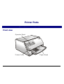
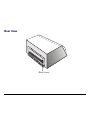
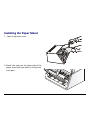
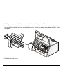
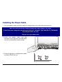
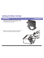
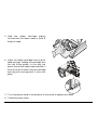
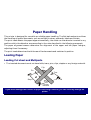
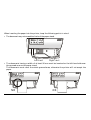
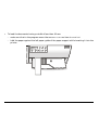
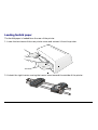
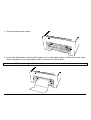
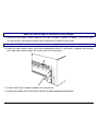
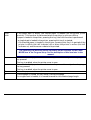
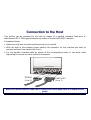
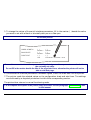
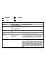
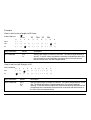
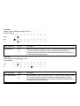
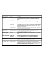
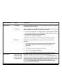
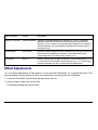
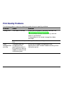
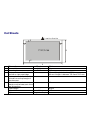
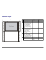
FB300
User Manual
Rev. 001
Table of Contents
Table of Contents ................................................. ii
Printer Presentation ............................................. 1
Unpacking the Printer .......................................... 3
Printer Parts.......................................................... 4
Front view ................................................................. 4
Rear View ................................................................. 5
Printer Installation................................................ 6
Choosing a Suitable Location................................... 6
Installing the Paper Stand ........................................ 7
Installing the Power Cable........................................ 9
Installing the Ribbon Cartridge ............................... 10
Paper Handling ................................................... 12
Loading Paper ........................................................ 12
Loading Cut sheet and Multiparts....................... 12
Loading fanfold paper ......................................... 15
The Operator Panel ............................................ 18
Function keys.......................................................... 18
Display .................................................................... 20
Leds ........................................................................ 21
Software Driver Selection .................................. 22
Connection to the Host ...................................... 23
Setting the Interface Parameters ........................... 24
Parallel Interface ................................................. 24
Serial Interface .................................................... 24
Printing a Test Page ...........................................26
Printer Setup .......................................................28
Printing the Printer Setup Forms............................ 28
Filling in the Printer Setup Forms ........................... 31
Reading the Preprinted Forms ............................... 31
Printer Setup Flow Chart ........................................ 32
Setup Parameters................................................... 33
Offset Adjustments ................................................. 42
Troubleshooting .................................................45
Clearing Paper Jams.............................................. 45
Print Quality Problems............................................ 48
Hexadecimal Dump ................................................ 49
Paper Specifications...........................................50
Cut Sheets.............................................................. 51
Fanfold Paper ......................................................... 52
Technical Specifications ....................................53
FCC Notes.............................................................. 56
Canadian D.O.C. Radio Interference Regulation... 56
EEC Regulations .................................................... 56
Printer Presentation
This dot-matrix printer is a multi-purpose printer for counter applications. Its compact structure
is designed to be integrated in an ergonomic environment. The printer provides a high level of
reliability, form-handling accuracy and data integrity. Its main features are:
• Printing on different types paper: cut sheets, multiparts and fanfold paper
• High print pressure for multipart documents
• High print quality supplied by a 24 wire print head
• High reliability paper handling
The straight paper path allows the printing on particular documents such as multipart forms.
• Automatic paper thickness adjustment
The print head detects automatically the paper thickness for correct printing on any type of
document.
• Easy paper handling
The cut sheets are placed on the front table by the operator and the printer loads it without
any other user intervention. The paper ejection towards the front or the rear of the printer
allows an easy access to the printed document.
For the fanfold paper the printer offers the zero tear-off feature, which allows a paper
handling without waste of paper, and the paper parking feature.
1
• Automatic switching between cut sheets and fanfold paper
If the paper path is empty (i.e. the fanfold paper is in the first line position), when inserting a
cut sheet into the printer, it is automatically loaded after the printer automatically parked
the fanfold paper. The fanfold paper can then be loaded again simply pressing the LOAD/PARK
key.
• Automatic document alignment feature
The printer checks automatically the alignment of the top margin and the left margin of the
document and adjusts it, if necessary. The printout is therefore performed correctly
independently from the paper loading position.
• Storage of four complete configurations for instant recall
• Standard parallel and serial interface and automatic switch-over function.
• Easy printer setup
• Supported emulations: IBM Proprinter XL24E, XL24E AGM, 2390+ and Epson 570
2
Unpacking the Printer
Together with the printer the following items are included in the shipment box:
Notify any damage to your supplier.
• Paper stand
• Ribbon cartridge
• Power cable
• CD-ROM with the printer documentation and drivers.
Always keep the packing material in a safe place as you must repack the printer into it, when you
need to move it.
3
Printer Parts
Never remove any printer part unless it is expressly indicated in this manual.
Front view
O p erato r P anel
P rinter C over
P aper S tan d
4
Rear View
R ear cover
5
Printer Installation
Choosing a Suitable Location
Consider the following points when you choose the location for your printer:
• The distance between the printer and the host computer must not exceed the length of the
interface cable;
• The location must be sturdy, horizontal and stable;
• Your printer must not be exposed to direct sunlight, extreme heat, cold, dust or humidity;
• You need an AC power outlet compatible with the plug of the printer’s power cord. The voltage
of the outlet must match the voltage shown on the printer’s Name Plate;
• When printing on standard paper formats, the paper is partially ejected on the rear side of the
printer. Make sure that behind the printer there is sufficient clearance to correctly move the
paper;
• Make sure that behind the printer there is sufficient clearance to easily load the fanfold
paper;
• Make sure that the power and interface cables do not hamper the fanfold paper while it is
loaded into the printer.
6
Installing the Paper Stand
1. Open the printer cover.
2. Match the hooks on the lower side of the
paper stand with the clefts on the printer
front part.
7
3. Holding the paper stand oblique insert the hooks into the printer clefts.
4. Lower the paper stand to horizontal position making sure that the two holders on both sides
are correctly inserted into the corresponding slots. Press the paper stand down until it clips
into place.
5. Close the printer cover.
8
Installing the Power Cable
1. Find the power cable connector and the rating plate on the rear side of the printer.
Make sure that your power supply matches the power rating of the printer.
In case the power rating does not correspond DO NOT CONNECT THE PRINTER TO THE MAINS.
Consult your dealer for help.
Always use a grounded outlet.
2. Insert the power cable into the
connector on the printer and the other
end into a convenient mains outlet.
3. Press the key on the operator panel
to power the printer on.
LQ
9
Installing the Ribbon Cartridge
To install the ribbon cartridge, the printer must be powered on.
1. Remove the cartridge from its bag. Turn
the tension knob in the direction of the
arrow to tighten the ribbon.
2. Open the printer cover, the print head
moves to the ribbon installation position.
10
3. Hold the ribbon cartridge slightly
inclined with the ribbon mask in front of
the print head.
4. Insert the ribbon cartridge into the print
head carriage, leading the cartridge pins
into the fixing guides. In this way you
assure the correct ribbon mask position in
front of the print head. Push the cartridge
onto the print carriage until it clicks into
place.
5. Turn the tension knob in the direction of the arrow to tighten the ribbon.
6. Close the printer cover.
11
Paper Handling
This printer is designed for versatile an reliable paper handling. The flat-bed mechanism allows
the handling of special documents, such as multiple invoices, postcards, labels and tickets.
The print head detects the paper edges automatically, the sheet can therefore be inserted in any
position within the detection area according to the rules described in the following paragraph.
The paper alignment sensors determine the alignment of the upper and left paper margins,
adjusting them if necessary.
The print head determines the thickness of the documents and matches its position.
Loading Paper
Loading Cut sheet and Multiparts
• The inserted documents must not have folds, tears, pins, clips, staples or any foreign material.
C lip
P in
Te a r
S ta p le
F old
F ore ig n
m ate ria l
If you insert damaged documents or paper with foreign material, you can seriously damage the
printer.
12
When inserting the paper into the printer, keep the following points in mind:
• The document may not exceed the limits of the paper stand.
R ight Lim it
Left Lim it
• The documents having a width of at least 90 mm must be inserted on the left hand side over
the grooved area on the paper stand.
The documents must cover the whole grooved area, otherwise the printer will not accept the
paper.
NO
OK
13
•
To load the documents having a width of less than 90 mm:
− make sure that in the program menu the MANUAL LOADING item is enabled.
− hold the paper against the left paper guide of the paper support while inserting it into the
printer
14
Loading fanfold paper
The fanfold paper is loaded form the rear of the printer.
1. Lower the two levers of the rear printer cover and unhook it from the printer.
2. Unhook the right tractor moving the tractor lever towards the outside of the printer.
15
3. Open the two tractor covers.
4. Insert the perforation of the fanfold paper on the left paper tractor. Close the tractor door.
Insert the paper on the right paper tractor and close the tractor door.
The upper margin of the inserted paper should not exceed the tractors.
16
Make sure, that the paper is inserted correctly (straight).
5. Move the right paper tractor towards the right to slightly tighten the paper. Lock the tractor
in that position moving the tractor lever towards the inside of the printer.
Make sure, that the paper is not too taught, otherwise it may tear.
6. Hook the rear tractor cover into the corresponding slots (1) and push it against the printer
until both rear tractor levers (2) firmly hook into the printer.
2
1
7. Press LOAD/PARK to load the paper into the printer.
To remove the paper from the printer follow the above sequence backwards.
17
The Operator Panel
The operator panel is located on the front left side of the printer and is composed of function keys
and leds with which you can easily check the printer status and select the functions as described
below:
P1
MICRO FEED
P2
LF
FF
P3
LQ
LOAD
PARK
P4
PROGRAM
ONLINE
Function keys
Turns the printer on or off.
To turn the printer off, this key must be pressed for at least 3 seconds.
LQ
Toggles between Letter Quality and Draft printing mode.
This key is active, when the printer is offline or when the printer is online and no
print data are in the buffer.
When pressed while powering the printer on, selects the printer setup mode. See “Printer
Setup” later in this manual.
18
LOAD
PARK
If the paper path is empty, the fanfold paper is loaded into the printer (LOAD
function). This function is performed when the printer is online or offline.
If paper is loaded in the printer, pressing this key, the PARK function is performed:
• a single sheet is loaded in the printer, pressing this key it is ejected;
• if the fanfold paper is loaded in the printer, pressing this key it is parked of the
printer is offline (ON LINE indicator off) or when the printer is online (ON LINE
indicator on) and there are no data to be printed.
The PARK key has different effects depending on the selection for the PARK
MODE item in the Program Setup. See the description of this item later in this
manual.
↑
↓
LF
FF
Moves the fanfold paper forward in microsteps or continuously when keeping the
key pressed.
This key is enabled, when the printer cover is open.
Moves the fanfold paper backwards in microsteps or continuously when keeping
the key pressed.
This key is enabled, when the printer cover is open.
Moves the paper one line.
If fanfold paper is loaded, the key moves it forward one page.
If a single sheet is loaded, it is moved forward for the selected page length.
19
PROGRAM
Selects one of the available configurations (P1, P2, P3 and P4 or a configuration
couple P1/P3 or P2/P4) if the PROGRAM LOCKED parameter is not enabled.
This key is active, when the printer is offline or when the printer is online and no
print data are in the buffer.
When pressed while powering the printer on, selects the offset adjustment page.
See “Offset Adjustment” later in this manual.
ON LINE
Toggles the printer between online and offline status.
When pressed while powering the printer on, selects the Self Test printout. See
“Printing a Test Page” in this manual.
Display
The display normally shows the printer name or is used to indicate fault states of the printer.
20
Leds
POWER
On, if the printer is powered on.
LQ
On, if the Letter Quality mode is selected.
P1, P2,
P3, P4
Indicate the currently selected configuration both in normal printing mode and
during the Printer Setup procedure. See “Printer Setup” later in this section.
If the INTERFACE TYPE function is set to auto+blink, when line 1 (parallel
interface) is selected for data transmission, the P1 indicator blinks.
If the INTERFACE TYPE function is set to auto+blink, when line 2 (serial interface)
is selected for data transmission, the P2 indicator blinks.
In case of fault condition P1, P2, P3 and P4 blink.
ON LINE
On, if the printer is online.
Off, if the printer is offline.
Blinks, when receiving printing data from host.
In case of a printer fault during the initialization of the LQ, P1, P2, P3, P4 and ON LINE indicators
blink contemporaneously. Turn the printer off and on again. If the problem is not solved, call the
Customer Service.
21
Software Driver Selection
At this point it is necessary to configure your printer for your application package. The
installation procedures depend upon the host environment.
Together with the printer you receive a CD-ROM containing the printer drivers for the Windows
environment. This printer supports the Plug&Play facility in the Windows95/98/2000®
environment.
If you want to install the printer in the Windows environment, insert the CD-ROM and follow
the instructions.
22
Connection to the Host
This printer can be connected to the host by means of a parallel standard Centronics or
bidirectional IEEE 1284 type interface or by means of the serial RS232C interface.
Proceed as follows:
1.
Make sure that both the host and the printer are turned off.
2.
With the help of the following figure identify the connector for the interface you want to
connect and insert the cable firmly into it.
3.
Fix the parallel interface cable by means of the corresponding hooks or the serial cable
tightening the screws on either side of the connector.
S E R IA L
(L in e 2)
PA R A LLE L
(L in e 1)
Make sure, that the interface cables do not hamper the fanfold paper while it is loaded into the
printer.
23
Setting the Interface Parameters
Parallel Interface
The parameters set for the parallel interface match most of the most common environments and
the printer can be used immediately after the connection to the host.
In case you need to modify the standard parameters see “Printer Setup” later in this section.
Serial Interface
Because of the great variety of the possible connection configurations, when you use the serial
interface you will need to set the parameters accordingly.
To assure a correct functioning of the printer connected through the serial interface, the
transmission parameters set for the printer must match the values set for the host. Check the
interface settings on the host and proceed as follows:
1. Press the LQ key while powering the printer on and keep it pressed until all leds turn briefly on.
The printer enters the Setup mode.
2. Insert a blank sheet in A4 or Letter format. The printer loads the sheet and stops. The P1, P2,
P3 and P4 leds are lit.
3. Press the PROGRAM key once. The P1, P2, P3 and P4 leds are unlit.
4. Press the LQ key. The printer prints the first configuration sheet.
24
5. To change the values of the serial interface parameters, fill in the marker ( ) beside the value
you want to set with a black or blue ball-point pen or a fiber-pen.
Do not use pencils.
W ORD LENG TH
BA U D R AT E
PA R IT Y B IT
( )
( )
d is a b le d *
e n a b le d
( )
( )
d is a b le d *
e n a b le d
( )
( )
DTR
X O N /XO F F * X O N /X O F F + D T R
( )
If more than one value is set for a parameter, the printer ignores these parameters and maintains
the currently set value.
Do not fill in the marker beside the title of the preprinted form, otherwise the printer will not be
able to read that page.
6. Once the serial interface parameters have been signed, insert the sheet back into the printer.
7. The printer reads the selected values on the configuration sheet and sets them. The settings
are confirmed by a # symbol printed on the left of the corresponding marker.
The printer then returns to normal functioning mode.
For a complete description of the printer setup procedure see the paragraph “Printer Setup” later
in this manual.
25
Printing a Test Page
It is now useful to test, if the printer has been correctly installed. For this purpose print the self
test page as follows.
1. Press the ON LINE key while powering the printer on and hold the key pressed until all leds
turn briefly on.
2. Insert a single sheet in A4 or Letter format.
The printer prints the Self-Test page. Check that the printout is correct. The following printout
example shows also the printer setup default values.
SELF TEST
FB300
: Code Version Vx.x
CONFIGURATION SETUP
DISPLAY LANG.
PROGRAM
PROGRAM LOCKED
ERROR BUZZER
JOB BUZZER
SECURITY MODE
AUTO GAP OFFSET
GET EDGE QUOTE
SKIP PERFORATION
TEAR ADJUST
xxxxxxxx CharGen:xxxxxxxx ver. x.xx
English
progr.1
no
1 beep
No beep
enabled
+0.000 mm
1/2”
disabled
+0,00 mm
26
INTERFACE TYPE
INPUT BUFFER
AUTOFEED SIGNAL
SLCT-IN SIGNAL
IGNORE PE
BUFFER CONTROL
ROBUST XON
WORD LENGTH
BAUD RATE
PARITY BIT
automatic
16 Kb
disabled
disabled
enabled
XON/XOFF
enabled
8 bit
9600 bps
none
PROGRAM SETUP
PROTOCOL
FONT
HORIZONTAL PITCH
VERTICAL PITCH
LOCK
FORM LENGTH
LEFT MARGIN
RIGHT MARGIN
TOP MARGIN
BOTTOM MARGIN
IBM C-SET
IBM COMPRESS
EPSON C-SET
NATION C-SET
CODE PAGE
LINE MODE
WRAP MODE
SLASHED ZERO
PRINT DIRECTION
EJECT ON FF
CUT SHEET EJECT
PARK MODE
TEAR MODE
MANUAL LOADING
ALIGN MODE
GAP MODE
VERT.POS 1/10”
VERT.ADJ 1/60”
HORIZ.POS 1/10”
HORIZ.ADJ 1/60”
PROGRAM 1
IBM XL24E
Draft
10 cpi
6 lpi
no lock
A4
0
0
96
0
0
IBM set 1
17.1 cpi
graphic
USA
CP437
LF=LF, CR=CR
autowrap
no
sw control
yes
on front
manual imm.
manual
disabled
fast
auto
0
0
0
0
PROGRAM 2
EPSON 570
Draft
10 cpi
6 lpi
no lock
A4
0
0
96
0
0
IBM set 1
17.1 cpi
graphic
USA
CP437
LF=LF, CR=CR
autowrap
no
sw control
yes
On front
manual imm.
manual
disabled
fast
auto
0
0
0
0
27
PROGRAM 3
IBM XL24E
Draft
10 cpi
6 lpi
no lock
#lines
72
0
96
0
0
IBM set 1
17.1 cpi
graphic
USA
CP437
LF=LF, CR=CR
autowrap
no
sw control
yes
on front
manual imm.
manual
disabled
fast
auto
0
0
0
0
PROGRAM 4
EPSON 570
Draft
10 cpi
6 lpi
no lock
#lines
72
0
96
0
0
IBM set 1
17.1 cpi
graphic
USA
CP437
LF=LF, CR=CR
autowrap
no
sw control
yes
on front
manual imm.
manual
disabled
fast
auto
0
0
0
0
Printer Setup
The default configuration of this printer matches most of the commonly used environments, but
it may be necessary to change some printer parameters. For this purpose it is necessary to use
preprinted forms to be used with the printer in configuration mode.
The following is the complete description of the Setup Procedure.
The detailed description of the parameters that can be set on the various preprinted forms are
described in the “Setup Parameters” paragraph, later in this manual.
To enter the Printer Setup Mode press and hold the LQ key for at least 1 second while powering
the printer on. The printer enters the Setup Mode.
Printing the Printer Setup Forms
If you already have the preprinted forms for the printer setup, go to “Filling in the Printer Setup
Forms” later in this manual.
Insert a blank sheet in A4 or Letter format. The printer loads the sheet and stops. The P1, P2, P3
and P4 leds are lit.
The ON LINE, PROGRAM and LQ keys are enabled.
If the LQ key is pressed immediately after the printer enters in Setup Mode, all printer setup
modules are printed.
28
If you press the ON LINE key:
• the printer self-test is printed. See “Printing a Test Page” before in this manual. In this way it
is possible to check the current printer parameters.
• once the self-test is finished, the printer remains in Setup Mode.
If you press the PROGRAM key:
• the Px leds change and you can select the Setup Page you want to print as follows:
P1
P2
P3
P4
P1
P2
P3
P4
P1
P2
P3
P4
All setup pages
Configuration page
Program 1 page
P1
P2
P3
P4
P1
P2
P3
P4
P1
P2
P3
P4
Program 2 page
Program 3 page
Program 4 page
= lit
= unlit
The printer setup forms contain all printer parameters and the values that can be set. The
current value is indicated by an asterisk (*).
For a detailed description of the parameters and the settings see “Setup Parameters” later in this
manual.
29
Each printer setup form is identified by a marker in the upper left corner of the page as follows:
Configuration Setup
Program 1
Program 3
Program 2
Program 4
If you press the LQ key:
The printing of the printer setup forms starts. The forms are printed according to the selection
made with the PROGRAM key.
If you select one of the Program couples P1/P3 or P2/P4 you can define one parameters set for
printing on cut sheets and one for fanfold. P1 and P2 define the values for printing on cut sheets,
whereas P3 and P4 define the printing parameters for the fanfold paper.
The program couples may be selected only if the same emulation is selected for the two
programs.
The selection of the Program Setup is made simply pressing the PROGRAM key. When passing
from one Program Setup to another, the printer resets before setting the parameters as defined
in the new program setup.
30
Filling in the Printer Setup Forms
To change the values of the parameters, fill in the marker ( ) beside the value you want to set
with a black or blue ball-point pen or a fiber-pen.
Do not use pencils.
AU TO FE ED S IG N AL ( )
( )
d is a b le d *
SL C T -IN SIG N AL
BU FF E R C O N TR O L
en a b le d
( )
( )
d is a b le d *
en a b le d
( )
( )
D TR
XO N /XO F F * X O N /X O F F +
( )
If more than one value is set for a parameter, the printer ignores these parameters and maintains
the currently set value.
Do not fill in the marker beside the title of the preprinted form, otherwise the printer will not be
able to read that page.
Reading the Preprinted Forms
When the Printer Setup Forms have been filled in, insert them back into the printer. The printer
is able to recognize the Setup Forms by means of the markers on these pages. The printer reads
the values marked for the various parameters and configures the printer accordingly.
The settings are confirmed by a # symbol printed on the left of the corresponding marker.
31
Printer Setup Flow Chart
+
P rin ter P ow ered-off
N o rm al M od e
LQ
P1
P2
P3
P4
P R OGR AM
ON L I N E
LQ
S e lf Te s t
P1
P2
P3
P4
P R OGR AM
LQ
+
P1
P2
P3
P4
+
P R OGR AM
LQ
P1
P2
P3
P4
+
P R OGR AM
LQ
P1
P2
P3
P4
+
P R OGR AM
LQ
P1
P2
P3
P4
P R OGR AM
LQ
32
!
Setup Parameters
The following is a listing of the setup parameters.
Configuration Sheet
Setup Parameter
Values
Description
RESTORE TO MFG
no
The selected values are not set to factory defaults.
all
The values set in all printer setups are reset to factory default
values.
config
The values set in the configuration setup are reset to factory default
values.
prog.1, prog. 2,
prog.3, prog 4
The values set in the corresponding program setup are reset to the
factory default values.
DISPLAY LANG.
English, Italian,
German, French,
Spanish
Defines the language of the display messages.
PROGRAM
progr.1, progr.2,
progr.3, progr.4,
progr.1/3, progr.2/4
Defines the default Program Setup or Setup couple. The program
couples may be selected only if the same emulation has been
selected for the two setups.
PROGRAM LOCKED no, yes
Locks the program setup selection. In case the lock is ‘enabled’ the
program setup cannot be changed pressing the PROGRAM key.
ERROR BUZZER
1 beep, no beep
Selects the behavior of the buzzer in case of an error.
JOB BUZZER
no beep, 1 beep,
continuous
Selects the behavior of the buzzer when a new print job begins: no
signal (no beep), one beep (1 beep) or a continuous beep
(continuous).
33
Setup Parameter
Values
Description
INTERFACE TYPE
parallel, serial, automatic,
auto+blink
Selects the interface type. In case of ‘automatic’ the interface
type is selected by the printer depending on data coming from
host. When the auto+blink item is selected, the P1 and P2
leds blink to indicate which interface is selected: P1 blinks
when the parallel interface is selected, whereas P2 blinks,
when the serial interface is selected.
INPUT BUFFER
1 Kb, 8 Kb, 16 Kb, 32 Kb
Selects the buffer size.
IGNORE PE
enabled, disabled
Selects whether the printer signals the paper empty condition
(disabled) or not (enabled).
AUTOFEED SIGNAL disabled, enabled
The parallel interface uses (enabled) or does not use
(disabled) the AUTOFEED signal.
SLCT-IN SIGNAL
disabled, enabled
The parallel interface uses (enabled) or does not use
(disabled) the SELECT-IN signal.
BUFFER CONTROL
DTR+SRTS, SRTS,
XON/XOFF,
XON/XOFF+DTR+SRTS
Selection of the buffer protocol.
ROBUST XON
enabled, disabled
Perform the Robust XON (enabled) or not (disabled).
WORD LENGTH
7 bit, 8 bit
Sets the number of the data bits.
BAUD RATE
600 - 38400 bps
Sets the data transfer rate.
PARITY BIT
even, odd, none
Selects the parity control for the data.
34
Setup Parameter
Values
Description
SECURITY MODE
enabled, disabled
Enables or disables the security actions that assure protection
against paper jams. If disabled, the paper handling is faster.
AUTO GAP OFFSET
-0,075 mm, -0.050 mm,
-0.025 mm, +0.000 mm,
+0.025 mm, +0.050 mm,
+0.075 mm, +0.100 mm
Sets the automatic gap offset to one of the given values.
GET EDGE QUOTE
0/2”, 1/2”, 2/2”, 3/2”, 4/2”, Sets the position in which the left paper edge is checked. If set
5/2”, 6/2”, 7/2”
to 0, the check is performed at the first line. The other values
correspond to the physical distance from the first line.
SKIP PERFORATION
disabled, enabled
If the movement of the paper perforation under the print head
is critical, select enabled to avoid the paper to get torn. The
print head lifts up while the paper perforation passes through.
If disabled, the print head stays in position.
TEAR ADJUST
-0,85 mm, -0,56 mm,
-0,28 mm, +0,00 mm,
+0,28 mm +0,56 mm,
+0,85 mm
Sets the paper tear-off position by aligning the paper with the
tear-off edge.
35
PROGRAM 1
PROGRAM 2
PROGRAM 3
PROGRAM 4
Setup Parameter
Values
Description
PROTOCOL
EPSON 570, IBM X24E,
IBM X24E AGM, IBM 2390
Defines the printer protocol.
FONT
Draft, Courier, OCR-B,
Gothic, Prestige, Present,
OCR-A, Script, Boldface
Selects the font.
HORIZONTAL PITCH
10 cpi, 12 cpi, 15 cpi, 17 cpi, Selects the character spacing in characters per inch (cpi).
20 cpi
VERTICAL PITCH
5 lpi, 6 lpi, 8 lpi,
Selects the line spacing in lines per inch (lpi).
LOCK
no lock, font, hor. pitch,
font+hor. pitch
The following selections made via operator panel may be
locked: font, horizontal pitch (hor.pitch), or both the font
and horizontal pitch (font+hor. pitch). The locked
settings cannot be changed via software commands.
FORM LENGTH
# lines, A4, letter, A5, legal
Sets the page length in number of lines or standard formats
A4, Letter, A5 or Legal. If you select # lines, you must
indicate the number of lines you want to set in the scheme
below this selection. The values range between 0 and 255.
To set the values combine the numbers considering that
the first line corresponds to the hundreds, the second line
to the tens and the third line to the units. See the example
below.
36
Example:
How to set the form length to 82 lines:
100 x
10 x
0
( )
( )
# lines
1
2
( )
( )
( )
1x
( )
( )
(
(
3
( )
A4
4
( )
( )
letter A5
5
6
( )
( )
( )
( )
( )
( )
( )
legal
7
8
9
( )
( )
(
(
(
(
FORM LENGTH
( )
( )
( )
( )
( )
Setup Parameter
Values
Description
LEFT MARGIN
10 x
1x
Sets the left margin in number of columns. The values range between 0
and 90. To set the values combine the numbers considering that the first
line corresponds to the hundreds, the second line to the tens and the
third line to the units. See the example below.
Example:
How to set the Left Margin to 20.
LEFT MARGIN
1
( )
2
10 x
0
( )
(
3
( )
4
( )
5
( )
6
( )
7
( )
8
( )
9
( )
1x
(
(
( )
( )
( )
( )
( )
( )
( )
( )
( )
(
Setup Parameter
Values
Description
RIGHT MARGIN
100 x
10 x
1x
Sets the right margin in number of columns. The values range between 0 and
190. The physical position of margin depends on the current character
spacing. To set the values combine the numbers considering that the first line
corresponds to the hundreds, the second line to the tens and the third line to
the units. See the example below:
37
Example:
How to set the Right Margin to 101.
RIGHT MARGIN
0
100 x
( )
1
10 x
(
1x
( )
2
3
4
5
6
7
8
9
( )
( )
( )
( )
( )
( )
( )
( )
( )
(
( )
( )
( )
( )
( )
( )
( )
( )
(
(
(
(
Setup Parameter
Values
Description
TOP MARGIN
10 x
1x
Sets the top margin in number of lines. The values range between 0 and 90.
To set the values combine the numbers considering that the first line
corresponds to the hundreds, the second line to the tens and the third line to
the units. See the example below.
Example:
How to set the Top Margin to 15.
TOP MARGIN
0
( )
1
10 x
1x
( )
(
3
( )
4
( )
5
( )
6
( )
7
( )
8
( )
9
( )
( )
( )
( )
( )
(
(
Setup Parameter
2
( )
( )
( )
( )
( )
(
Values
BOTTOM MARGIN 10 x
1x
Description
Sets the bottom margin in number of lines. The values range between 0 and
90. To set the values combine the numbers considering that the first line
corresponds to the hundreds, the second line to the tens and the third line to
the units. See the example below.
38
Example:
How to set the bottom margin to 34 lines:
1
( )
2
( )
3
1x
( )
( )
( )
(
( )
(
4
( )
5
( )
6
( )
7
( )
8
( )
9
( )
(
BOTTOM MARGIN
0
10 x
( )
( )
( )
( )
( )
( )
(
Setup Parameter
IBM C-SET
IBM COMPRESS
Values
IBM set 1, IBM set 2
17.1 cpi, 20 cpi
EPSON C-SET
NATION C-SET
italic, graphic
USA, FRANCE, GERMANY, ENGLAND,
DENMARK1, SWEDEN, ITALY, SPAIN1,
JAPAN, NORWAY, DENMARK2,
SPAIN2, LATIN A1
CODE PAGE
CP437, CP437G, 96GREEK, CP850,
Selects the code page for both the IBM and the
CP851, CP852, CP853, CP855, CP857,
EPSON emulations.
CP858, CP860, CP862, CP863, CP864,
CP865, CP866, CP867, CP876, CP877,
CP1098, CP1250, CP1251, CP1252,
GOST, TASS, MAZOWIA, CP437SL,
UKRAIN, 8859/1, 8859/2, 8859/3, 8859/4,
8859/5, 8859/6, 8859/7, 8859/8, 8859/9,
8859/15, ROMAN-8, ID 12, CP874, ID 14,
ID 17, SANYO, KU, PHILIP
39
Description
Selects the IBM character set.
Selects the pitch for the compressed mode
printing in IBM emulation.
Selects italic or graphic Epson character set.
Selects the national character sets.
Setup Parameter
Values
Description
LINE MODE
LF=LF, CR=CR
If the printer receives a LF code (LF), it only performs a line feed. If
the printer receives a CR code (CR), it only performs a carriage
return.
CR=LF+CR
If the printer receives a CR code (CR), it perf