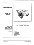
1
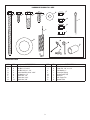
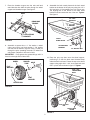
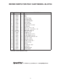
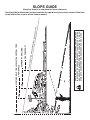
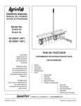
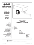
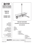
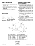
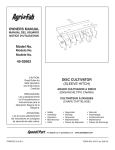
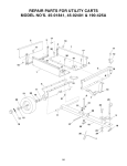
™
owners
manual
Model No.
45-01754
EXPLORER
POLY ATV CART
CAUTION:
Read Rules for
Safe Operation
and Instructions
Carefully
IMPORTANT!
The wheel bearings are not prelubricated.
The wheel hubs must be filled with grease after the wheels
are assembled to the axle.
• Assembly
• Operation
• Maintenance
• Repair Parts
the fastest way to purchase parts www.speedepart.com
PRINTED IN USA
FORM NO. 40757 (08/24/07)
SAFETY RULES
Remember, any power equipment can cause injury if operated improperly or if the user does not understand how to operate
the equipment. Exercise caution at all times when using power equipment.
CAUTION: VEHICLE BRAKING AND
STABILITY MAY BE AFFECTED WITH THE
ADDITION OF AN ACCESSORY OR AN
ATTACHMENT. BE AWARE OF CHANGING
CONDITIONS ON SLOPES.
LOOK FOR THIS SYMBOL TO POINT OUT
IMPORTANT SAFETY PRECAUTIONS. IT
MEANS — ATTENTION! BECOME ALERT!
YOUR SAFETY IS INVOLVED.
Exercise caution at all times when using power equipment.
• Read this owners manual before attempting to assemble or operate the cart.
• Read the vehicle owners manual and know how to operate your vehicle before using the cart attachment.
• Do not at any time carry passengers in this cart. It has not been designed to carry passengers.
• Never allow children to operate the vehicle or the cart attachment.
• Do not allow adults to operate the vehicle or cart attachment without proper instructions.
• Always begin with the transmission in first (low) and gradually increase speed as conditions permit.
• Tow the cart at reduced speed over rough terrain and hillsides or near creeks and ditches to prevent tipping over and
loss of control. Do not drive too close to a creek or ditch.
• Vehicle braking and stability may be affected with the attachment of this cart. Do not fill cart to maximum weight
capacity without checking the capability of the towing vehicle to safely pull and stop with the cart attached.
• Before operating vehicle on any grade (hill) refer to the safety rules in the vehicle owner's manual concerning safe
operation on slopes. Refer also to the slope guide on page 11 of this manual. Stay off steep slopes!
• Do not tow this cart on highways or on public thoroughfares.
• Maximum towing speed is 10 m.p.h.
• Follow maintenance and lubrication instructions as outlined in this manual.
CARTON CONTENTS (Loose Parts)
1.
2.
3.
4.
Poly Tray
Wheel Support
Latch Stand Plate
Latch Stand Bracket
5. Axle
6. Wheels (2)
7. Draw Bar Tongue
8. Latch Lock Lever
9. Hitch Bracket
3
1
2
4
8
5
CARTON CONTENTS
6
7
2
9
HARDWARE SHOWN FULL SIZE
B
A
C
F
E
D
G
J
H
L
I
Not Shown Full Size
K
M
N
P
O
HARDWARE PACK
ref.
A
B
C
D
E
F
G
H
qty.
1
2
4
2
8
4
4
11
description
Hex Bolt, 5/16" x 3-3/4"
Hex Bolt, 1/4" x 3/4"
Hex Bolt, 3/8" x 1-1/4"
Truss Head Bolt, 5/16" x 3/4"
Flat Washer, 1/4"
Nylock Nut, 1/4"
Nylock Nut, 5/16"
Nylock Nut, 3/8"
ref.
I
J
K
L
M
N
O
P
3
qty.
2
2
4
1
1
1
1
2
description
SEMS Nut, 5/16"
Cotter Pin, 1/8" x 1-1/2"
Flat Washer, 1"
Extension Spring
Spring Puller Tool
Hitch Pin
Hair Cotter Pin
Spacer Tube
ASSEMBLY INSTRUCTIONS
4. Hook the short end of the spring into the hole in the
latch lock lever. Use the spring puller tool to hook
the long end of the spring into the square hole in the
tongue. The spring puller tool can be stored when
finished. See figure 2.
TOOLS REQUIRED FOR ASSEMBLY
(1)
Screwdriver
(1)
Pliers
(2)
7/16" Wrenches
(2)
1/2" Wrench
(2)
9/16" Wrenches
SPRING PULLER TOOL
1. Remove the hardware pack and all loose parts from
the carton. Be sure the carton is empty before
discarding.
2. Lay out and identify all the parts and hardware as
shown on pages 2 and 3.
3. Place the latch lock lever through the slot in the draw bar
tongue. Assemble the 5/16" x 3-3/4" hex bolt through
the tongue, lever and two 5/16" hex nuts (SEMS) (one
on each side of the lever). Assemble a 5/16" nylock
nut onto the end of the bolt and tighten so that the
bolt can still rotate freely. Tighten the two 5/16" nylock
nuts against the sides of the latch lock lever so that
the lever is centered in the slot. See figure 1.
LONG END
OF SPRING
LATCH LOCK
LEVER
FIGURE 2
5/16" HEX NUTS (SEMS)
5. Assemble the end of the hitch bracket to the front of
the drawbar tongue using two 3/8" x 1-1/4" hex bolt
and 3/8" nylock nut. Tighten. See figure 3.
6. Assemble the hitch pin to the tongue and hitch bracket
and secure it with the hair cotter pin. See figure 3.
LATCH
LOCK
LEVER
5/16"
NYLOCK
NUT
HITCH PIN
HITCH
BRACKET
DRAWBAR TONGUE
3/8" x 1-1/4"
HEX BOLT
5/16" x 3-3/4"
HEX BOLT
HAIR
COTTER
PIN
FIGURE 1
3/8" NYLOCK
NUT
FIGURE 3
4
7. Place the drawbar tongue onto the axle and latch
stand bracket then slide the axle through the wheel
support and drawbar tongue. See figure 4.
9. Assemble the latch stand plate and the latch stand
bracket to the bottom of the poly tray using four 1/4" x
3/4" hex bolts, 1/4" flat washers and 1/4" nylock nuts.
The aligning tab on the bottom of the latch stand
bracket must be towards the rear of the cart. Tighten.
See figure 6.
AXLE
1/4" x 3/4"
HEX BOLT
DRAW BAR
TONGUE
1/4" FLAT
WASHER
LATCH STAND
BRACKET
LATCH
STAND PLATE
FIGURE 4
8. Assemble a spacer tube, a 1" flat washer, a wheel
(valve stem facing out) and another 1" flat washer
onto the axle as shown in figure 5. Insert a cotter pin
through the axle, spreading the ends. Fill wheel hub
with grease. Repeat on other end of axle.
IMPORTANT: Pump grease into grease fittings until it is
forced out through ends of wheel hub.
WHEEL
SPACER
TUBE
TAB
LATCH STAND
BRACKET
1/4" NYLOCK NUT
FIGURE 6
10. Place the poly tray down onto the wheel support,
positioning it so that the latch stand bracket snaps
under the latch lock lever. Fasten the tray to the wheel
support using eight 5/16" x 3/4" truss head bolts and
5/16" nylock nuts as shown in figure 7. Tighten.
AXLE
FLAT
WASHER
5/16" x 3/4"
TRUSS HEAD
BOLT
FLAT
WASHER
COTTER PIN
FIGURE 5
5/16" NYLOCK
NUT
LATCH LOCK
LEVER
FIGURE 7
5
OPERATION
MAINTENANCE
CAUTION: VEHICLE BRAKING AND
STABILITY MAY BE AFFECTED WITH THE
ADDITION OF AN ACCESSORY OR AN
ATTACHMENT. BE AWARE OF CHANGING
CONDITIONS ON SLOPES.
1. At the beginning of each season, using a light machine
oil, lubricate the latch, the latch pivot bolt, and the area
of the axle where the draw bar tongue pivots.
2. At the beginning of each season, grease the wheel
bearings. Apply grease through the grease fitting until
grease if forced out through the ends of the wheel
hub.
1. Refer to the vehicle owners manual for instructions on
safe operation on slopes.
3. Check periodically for loose bolts.
2. Use the slope guide provided on page 11 of this
manual to determine whether slope angle is too steep
for safe operation.
4. Keep tires filled. Do not exceed maximum tire pressure
of 10 Lbs.
3. For best handling and traction, distribute the weight of
the load evenly in the cart.
4. Always test to make sure your vehicle has adequate
towing and braking capabilities whenever hauling a
substantial amount of weight in your cart. Use extra
caution when operating on slopes.
NOTE
CART SPECIFICATIONS
DO NOT EXCEED WEIGHT CAPACITY OF CART
(See the specifications on this page.)
One cubic foot of dirt weighs approximately 80 lbs.
Tires:
Axle:
Capacity:
Approx. Sh. Wt.
5. To dump material from the cart, release the spring
latch on the tongue by pulling the latch lock lever
forward, away from the cart. The cart bed will then tilt
backwards to empty its contents. After emptying, pull
the front of the bed down toward the cart tongue until
the latch snaps into place.
6. The maximum towing speed for this cart is 20 m.p.h.
CAUTION: TO AVOID POSSIBLE
INJURY, BEFORE RELEASING THE
LATCH BE SURE THAT NO ONE IS
NEAR THE CART.
6
18" x 9.5" Pneumatic
1" Dia. Steel
Up to 650 Lbs. Max.
100 Lbs.
NOTES
7
REPAIR PARTS FOR POLY CART MODEL 45-01754
21
18
15
1
5
19
6
7
3
26
8
12 13
23
12
17
20
17
2
16
B
26
2
20
10
4
11
B
9
22
25
8
14
24
REPAIR PARTS FOR POLY CART MODEL 45-01754
ref.
1
2
3
4
5
6
7
8
9
10
11
12
13
14
15
16
17
18
19
20
21
22
23
24
25
26
part no.
47019
25636
40758
24758
24386
24497
24527
24498
47407
23475
43093
43601
47453
HA21362
43088
43087
46980
43814
47189
47810
43012
47408
23353
43343
47622
65408
40757
qty.
1
1
2
1
1
1
1
1
1
1
2
4
2
1
4
1
2
8
4
9
4
1
1
1
1
2
1
description
Poly Tray
Axle, 1"
Wheel
Draw Bar Tongue
Latch Stand Plate
Latch Stand Bracket
Wheel Support
Latch Lock Lever
Hex Bolt, 5/16-18 x 3-3/4"
Hitch Bracket
Cotter Pin, 1/8" x 1-1/2"
Washer, Flat 1.59" O.D. x 1" I.D.
Spacer Tube, 3-1/8" Lg.
Nylock Nut, 3/8-16*
Flat Washer, 1/4"
Hex Bolt, 3/8-16 x 1-1/4" *
Hex Nut (SEMS), 5/16-18
Truss Head Bolt, 5/16-18 x 3/4"
Nylock Nut, 1/4-20
Nylock Nut, 5/16-18
Hex Bolt, 1/4-20 x 3/4" *
Extension Spring
Hitch Pin
Hair Cotter Pin, 3/32"
Spring Puller
Wheel Bearing Kit
Owners Manual
* Purchase Common Hardware Locally
the fastest way to purchase parts www.speedepart.com
9
10
DEGRE
E SLO
PE
CAUTION: DO NOT OPERATEYOUR TRACTOR AND CART ON A SLOPE
IN EXCESS OF 10 DEGREES. BE SURE OF YOUR TRACTOR'S TOWING
AND BRAKING CAPABILITIES BEFORE OPERATING ON A SLOPE.
AVOID ANY SUDDEN TURNS OR MANEUVERS WHILE ON A SLOPE.
FOLD A
LONG
DOTTE
D LINE
, REPR
ESENT
ING A
10
OR A FENCE POST
A CORNER OF A BUILDING
A POWER POLE
SIGHT AND HOLD THIS LEVEL WITH A VERTICAL TREE
(Keep this sheet in a safe place for future reference.)
Use this guide to determine if a slope is safe for the operation of your tractor and cart. Refer also
to the instructions in your vehicle owners manual.
SLOPE GUIDE
the fastest way to purchase parts www.speedepart.com
REPAIR PARTS
Agri-Fab, Inc.
809 S. Hamilton
Sullivan, IL. 61951
217-728-8388
www.agri-fab.com
This document (or manual) is protected under the U.S. Copyright Laws and the copyright laws of foreign countries,
pursuant to the Universal Copyright Convention and the Berne convention. No part of this document may be reproduced
or transmitted in any form or by an means, electronic or mechanical, including photocopying or recording, or by any
information storage or retrieval system, without the express written permission of Agri-Fab, Inc. Unauthorized uses and/or
reproductions of this manual will subject such unauthorized user to civil and criminal penalties as provided by the United
States Copyright Laws.
© 2004 Agri-Fab, Inc.
12