1
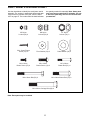
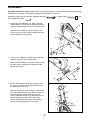
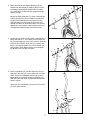
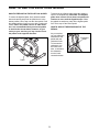
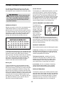
Patent Pending
Model No. 831.285250
Serial No.
Write the serial number in the
space above for future reference.
Serial
Number
Decal
USER’S
MANUAL
CAUTION
Read all precautions and
instructions in this manual
before using this equipment.
Keep this manual for future
reference.
SEARS, ROEBUCK AND CO., HOFFMAN ESTATES, IL 60179
TABLE OF CONTENTS
IMPORTANT PRECAUTIONS . . . . . . . . . . . . . . . . . . . . . . . . . . . . . . . . . . . . . . . . . . . . . . . . . . . . . . . . . . . . .3
BEFORE YOU BEGIN . . . . . . . . . . . . . . . . . . . . . . . . . . . . . . . . . . . . . . . . . . . . . . . . . . . . . . . . . . . . . . . . . . .4
PART IDENTIFICATION CHART . . . . . . . . . . . . . . . . . . . . . . . . . . . . . . . . . . . . . . . . . . . . . . . . . . . . . . . . . . .5
ASSEMBLY . . . . . . . . . . . . . . . . . . . . . . . . . . . . . . . . . . . . . . . . . . . . . . . . . . . . . . . . . . . . . . . . . . . . . . . . . . .6
HOW TO USE THE ELLIPTICAL GLIDER . . . . . . . . . . . . . . . . . . . . . . . . . . . . . . . . . . . . . . . . . . . . . . . . . . . .9
MAINTENANCE . . . . . . . . . . . . . . . . . . . . . . . . . . . . . . . . . . . . . . . . . . . . . . . . . . . . . . . . . . . . . . . . . . . . . . .11
CONDITIONING GUIDELINES . . . . . . . . . . . . . . . . . . . . . . . . . . . . . . . . . . . . . . . . . . . . . . . . . . . . . . . . . . . .12
PART LIST . . . . . . . . . . . . . . . . . . . . . . . . . . . . . . . . . . . . . . . . . . . . . . . . . . . . . . . . . . . . . . . . . . . . . . . . . . .14
EXPLODED DRAWING . . . . . . . . . . . . . . . . . . . . . . . . . . . . . . . . . . . . . . . . . . . . . . . . . . . . . . . . . . . . . . . . .15
HOW TO ORDER REPLACEMENT PARTS . . . . . . . . . . . . . . . . . . . . . . . . . . . . . . . . . . . . . . . . . . .Back Cover
FULL 90 DAY WARRANTY . . . . . . . . . . . . . . . . . . . . . . . . . . . . . . . . . . . . . . . . . . . . . . . . . . . . . . .Back Cover
2
IMPORTANT PRECAUTIONS
WARNING:
To reduce the risk of serious injury, read the following important precautions before using the LIFESTYLER® ET 30 elliptical glider.
1. Read all instructions in this manual before
using the elliptical glider.
8. Wear appropriate clothing when using the
elliptical glider. Always wear athletic shoes
for foot protection.
2. Use the elliptical glider only as described in
this manual.
9. When mounting and dismounting the elliptical glider, always hold the handlebars and
step onto and off the pedal that is in the
lowest position.
3. It is the responsibility of the owner to
ensure that all users of the elliptical glider
are adequately informed of all precautions.
10. Each time you stop exercising on the
elliptical glider, allow the pedals to come to
a complete stop before dismounting.
4. Place the elliptical glider on a level surface,
with a mat beneath it to protect the floor or
carpet. Keep the elliptical glider indoors,
away from moisture and dust.
11. Always keep your back straight when using
the elliptical glider. Do not arch your back.
5. Inspect and tighten all parts regularly.
Replace any worn parts immediately.
12. If you feel pain or dizziness at any time
while exercising, stop immediately and
begin cooling down.
6. Keep children under the age of 12 and pets
away from the elliptical glider at all times.
13. The elliptical glider is intended for in-home
use only. Do not use the elliptical glider in a
commercial, rental, or institutional setting.
7. The elliptical glider should not be used by
persons weighing more than 250 pounds.
WARNING:
Before beginning this or any exercise program, consult your physician.
This is especially important for persons over the age of 35 or persons with pre-existing health
problems. Read all instructions before using. SEARS assumes no responsibility for personal injury
or property damage sustained by or through the use of this product.
3
BEFORE YOU BEGIN
Congratulations for selecting the LIFESTYLER® ET 30
elliptical glider. The ET 30 is an incredibly smooth
exerciser that moves your feet in a natural elliptical
path, minimizing the impact on your knees and ankles.
And the unique ET 30 features adjustable resistance,
upper-body handlebars, and a multi-mode exercise
monitor to help you get the most from your exercise.
Welcome to a whole new world of natural, ellipticalmotion exercise.
questions, please call our toll-free HELPLINE at
1-800-736-6879, Monday through Saturday, 7 a.m.
until 7 p.m. Central Time (excluding holidays). To help
us assist you, please note the product model number
and serial number before calling. The model number
is 831.285250. The serial number can be found on a
decal attached to the elliptical glider (see the front
cover of this manual for the location of the decal).
Before reading further, please look at the drawing
below and familiarize yourself with the parts that are
labeled.
For your benefit, read this manual carefully before
you use the elliptical glider. If you have additional
Handlebar
Remote Holder
Water Bottle Holder
(Bottle not included)
FRONT
Upright
Resistance Knob
Side Shield
LEFT SIDE
Pedal
Pedal Arm
BACK
4
PART IDENTIFICATION CHART
Use the chart below to identify the small parts used in
assembly. The number in parenthesis below each part
refers to the key number of the part, from the PART
LIST on page 14. The number after the dash indicates
the quantity needed for assembly. Note: Some parts
may have been pre-attached for shipping. If a part
is not in the parts bag, check to see if it has been
pre-attached.
M5 Nylon
Locknut (52)–4
M8 Nylon
Locknut (50)–8
1/2” Nylon
Locknut (35)–2
M4 x 19mm Flange
Screw (55)–6
Pivot Washer (54)–2
Pedal Washer (32)–2
M4 x 12mm
Button Screw (57)–4
M8 x 19mm
Button Screw (10)–2
M5 x 30mm
Button Bolt (51)–4
M8 x 60mm Bolt (56)–2
M8 x 38mm Button Bolt (53)–2
M8 x 63mm Carriage Bolt (49)–4
Note: Extra parts may be included.
5
ASSEMBLY
Assembly requires two people. Place all parts of the elliptical glider in a cleared area and remove the packing
materials. Do not dispose of the packing materials until assembly is completed.
Assembly requires that you have two adjustable wrenches
the included allen wrench
.
1. Identify the Front Stabilizer (18), which is the narrowest Stabilizer. If there are no Stabilizer Endcaps
(20) on the Front Stabilizer, push one onto each end.
, a rubber mallet
, and
1
50
Attach the Front Stabilizer (18) to the front of the
Frame (1) with two M8 x 63mm Carriage Bolts (49)
and two M8 Nylon Locknuts (50).
1
50
18
20
20
49
2. If there are no Stabilizer Endcaps (20) on the Rear
Stabilizer (19), push one onto each end.
2
Attach the Rear Stabilizer (19) to the Frame (1) with
two M8 x 63mm Carriage Bolts (49) and two M8
Nylon Locknuts (50).
20
50
1
19
50
20
3. While a second person holds the Upright (2) near
the Frame (1), connect the Extension Wire (47) to
the Reed Switch Wire (41).
49
3
2
Insert the Upright (2) into the Frame (1), being careful to avoid damaging the wires. Make sure that the
Frame Bushings (3) are inserted fully into the
Frame. Adjust the Upright (2) so that a bolt can be
inserted through the center hole in each side.
Secure the Upright with two M8 x 38mm Button
Bolts (53) and two M8 Nylon Locknuts (50).
3
3
47
41
50
6
50
1
53
4. Make sure that the two Upright Bushings (8) are
inserted into the Upright (2). Apply a thin film of the
included grease along the length of the Pivot Axle
(11). Insert the Pivot Axle into the Upright Bushings
and the Upright.
54
4
9
8
9
10
8
Identify the Right Pivot Arm (7), which is marked with
a sticker that has an “R” on it. Make sure that there
are two Pivot Bushings (9) in the Right Pivot Arm.
Slide the Right Pivot Arm onto the Pivot Axle (11),
making sure that it is oriented as shown. Put a Pivot
Washer (54) onto an M8 x 19mm Button Screw (10)
and tighten the Button Screw into the Pivot Axle.
5. Identify the Left Pivot Arm (6), which is marked with a
sticker that has an “L” on it. Make sure that there are
two Pivot Bushings (9) in the Left Pivot Arm. Slide the
Left Pivot Arm onto the Pivot Axle (11), making sure
that it is oriented as shown. Put a Pivot Washer (54)
onto an M8 x 19mm Button Screw (10) and tighten
the Button Screw into the Pivot Axle.
7
11
2
Grease
5
11
9
10
9
54
6. Insert a Handlebar (12) into the Right Pivot Arm (7).
Slide the Foam Grip (13) up to expose the mounting
holes. Secure the Handlebar with two M5 x 30mm
Button Bolts (51) and two M5 Nylon Locknuts (52).
Slide the Foam Grip down over the Button Bolts and
Nylon Locknuts.
6
6
Attach the other Handlebar (12) to the Left Pivot Arm
(6) in the same manner.
13
12
51
52
7
6
7
7. Identify the Left Pedal Arm (14), which is marked with
a sticker that has an “L” on it. Next, identify the Left
Pedal (16), which has an “L” molded into the bottom.
Attach the Left Pedal to the Left Pedal Arm with three
M4 x 19mm Flange Screws (55).
7
16
Attach the Right Pedal to the Right Pedal Arm (not
shown) in the same manner.
14
55
8. Identify the Left Pedal Arm (14), which is marked with
a sticker that has an “L” on it. Make sure that there are
two Pedal Arm Bushings (33) in the Left Pedal Arm.
Apply a thin film of the included grease to a Pedal
Axle (34). Insert the Pedal Axle into the Left Pedal
Arm, and slide a Pedal Washer (32) onto the Pedal
Axle. Firmly tighten the Pedal Axle into the Crank (30).
Tighten a 1/2” Nylon Locknut (35) onto the end of the
Pedal Axle protruding from the Crank.
8
6
42
42
56
Make sure that there are two Small Pivot Bushings
(42) in the Left Pivot Arm (6). Apply a thin film of the
included grease to an M8 x 60mm Bolt (56). Attach
the Left Pivot Arm to the Left Pedal Arm (14) with the
Bolt and an M8 Nylon Locknut (50).
50
35
33
32
Grease
30
33
14
Attach the Right Pedal Arm (not shown) in the same
manner.
9. The Console (5) requires two “AA” batteries (not
included). Alkaline batteries are recommended.
34
9
To install batteries, look under the Console (5) and
locate the battery compartment. Insert two batteries
into the battery compartment; make sure that the
batteries are turned so the negative ends (marked
“–”) are touching the springs in the battery compartment.
Connect the console wire to the Extension Wire (47).
Attach the Console (5) to the Upright (2) with four M4
x 12mm Button Screws (57).
Console
Wire
5
47
2
5
28
Batteries
29
57
Push the Resistance Knob (28) firmly onto the
Resistance Cable (29).
10. Make sure that all parts of the elliptical glider are properly tightened. Place a mat under the elliptical glider
to protect the floor or carpet from damage.
8
HOW TO USE THE ELLIPTICAL GLIDER
HOW TO EXERCISE ON THE ELLIPTICAL GLIDER
To dismount the elliptical glider, allow the pedals to
come to a complete stop. CAUTION: The elliptical
glider does not have a free wheel; the pedals will
continue to move until the flywheel stops. When
the pedals are stationary, step off the highest pedal
first. Then, step off the lowest pedal.
To mount the elliptical glider, firmly hold the handlebars and carefully step onto the pedal that is in the
lowest position. Next, step onto the other pedal. Push
the pedals until they begin to move with a continuous
motion. Note: The pedals can turn in either direction. It is recommended that you turn the pedals
in the direction shown below; however, to give
variety to your exercise, you may choose to turn
the pedals in the opposite direction.
HOW TO ADJUST THE RESISTANCE OF THE
PEDALS
As you exercise,
you can adjust the
resistance of the
pedals with the
resistance knob.
To increase the
resistance, turn
the knob clockwise; to decrease
the resistance,
turn the knob
counterclockwise.
Pedal
9
Resistance
Knob
DESCRIPTION OF THE CONSOLE
HOW TO OPERATE THE CONSOLE
1. To turn on the power, press the on/reset button or
simply begin pedaling. When the power is turned
on, the entire display will appear for two seconds.
The console will then be ready for operation.
2. Select one of the five modes:
Scan mode—
When the
power is
turned on, the
scan mode will
automatically
Mode Indicators
be selected.
One mode
indicator will show that the scan mode is selected,
and a flashing mode indicator will show which
mode is currently displayed. Note: If a different
mode is selected, you can select the scan mode
again by repeatedly pressing the display button.
The innovative console features five modes that display instant exercise feedback. The modes are
described below:
Speed—This mode shows your exercise pace, in revolutions per minute.
Revolutions—This mode shows the total number of revolutions you have pedaled.
Speed, time,
revolutions, or
calories
mode—To
select one of
these modes
Mode Indicator
for continuous
display,
repeatedly press the display button. The mode indicators will show which mode is selected. (Make
sure that the scan mode is not selected.)
Calories—This mode shows the approximate number
of calories you have burned.
Time—This mode will show the elapsed time. Note:
When you stop exercising, the time will flash when it
is displayed.
Scan—This mode displays the other four modes, for
five seconds each, in a repeating cycle.
BATTERY INSTALLATION
3. To reset the display, press the on/reset button.
Before the console can be operated, two “AA” batteries must be installed. If you have not installed batteries, see assembly step 9 on page 8. Note: It will be
necessary to remove the console to install batteries.
4. To turn off the power, simply wait for about four
minutes. Note: The console has an “auto-off”
feature. If the pedals are not moved and the
console buttons are not pressed for four minutes, the power will turn off automatically in
order to conserve the batteries.
10
MAINTENANCE
Inspect and tighten all parts of the elliptical glider
regularly. Replace any worn parts immediately.
CONSOLE TROUBLE-SHOOTING
If the console does not function properly, the batteries
should be replaced. To replace the batteries, refer to
assembly step 9 on page 8. Note: It will be necessary
to remove the console to replace the batteries.
The elliptical glider can be wiped clean with a soft
cloth and mild detergent. Do not use abrasives or
solvents. To prevent damage to the console, keep
liquids away from the console. Use only a sealable
water bottle in the console.
STORAGE
When storing the elliptical glider, remove the batteries
from the console. Keep the elliptical glider in a clean,
dry location, away from moisture and dust.
11
CONDITIONING GUIDELINES
The following guidelines will help you to plan your
exercise program. Remember that proper nutrition
and adequate rest are essential for successful results.
Aerobic Exercise
To strengthen your cardiovascular system, your exercise must be “aerobic.” Aerobic exercise is activity
that requires large amounts of oxygen for prolonged
periods of time. This increases the demand on the
heart to pump blood to the muscles, and on the lungs
to oxygenate the blood. For aerobic exercise, adjust
the intensity of your exercise until your heart rate is
near the largest number in your training zone.
WARNING:
Before beginning this
or any exercise program, consult your physician. This is especially important for persons
over the age of 35 or persons with pre-existing health problems.
HOW TO MEASURE YOUR HEART RATE
EXERCISE INTENSITY
To measure your
heart rate, first exercise for at least four
minutes. Then, stop
exercising and place
two fingers on your
wrist as shown.
Take a six-second
heartbeat count,
and multiply the result by 10 to find your heart rate.
For example, if your six-second heartbeat count is 14,
your heart rate is 140 beats per minute. (A six-second
count is used because your heart rate will drop rapidly
when you stop exercising.)
Whether your goal is to burn fat or to strengthen your
cardiovascular system, the key to achieving the
desired results is to exercise with the proper intensity.
The proper intensity level can be found by using your
heart rate as a guide. The chart below shows recommended heart rates for fat burning, maximum fat
burning, and cardiovascular (aerobic) exercise.
WORKOUT GUIDELINES
Each workout should include the following three parts:
A warm-up, consisting of 5 to 10 minutes of stretching
and light exercise (see page 13). A proper warm-up
increases your body temperature, heart rate, and circulation in preparation for exercise.
To find the proper heart rate for you, first find your age
at the bottom of the chart (ages are rounded off to the
nearest ten years). Next, find the three numbers
above your age. The three numbers are your “training
zone.” The smallest number is the recommended
heart rate for fat burning; the middle number is the
heart rate for maximum fat burning; the largest
number is the heart rate for aerobic exercise.
Training zone exercise, consisting of 20 to 30
minutes of exercising with your heart rate in your
training zone. (During the first few weeks of your
exercise program, do not keep your heart rate in
your training zone for longer than 20 minutes.)
Burning Fat
A cool-down, with 5 to 10 minutes of stretching.
This will increase the flexibility of your muscles
and will help to prevent post-exercise problems.
To burn fat effectively, you must exercise at a low
intensity level for a sustained period of time. During
the first few minutes of exercise, your body uses easily accessible carbohydrate calories for energy. Only
after the first few minutes of exercise does your body
begin to use stored fat calories for energy. If your goal
is to burn fat, adjust the intensity of your exercise until
your heart rate is near the smallest number in your
training zone as you exercise. For maximum fat burning, adjust the intensity of your exercise until your
heart rate is near the middle number.
EXERCISE FREQUENCY
To maintain or improve your condition, plan three workouts each week, with at least one day of rest between
workouts. After a few months of regular exercise, you
may plan up to five workouts each week, if desired.
Remember, the key to success is make exercise a
regular and enjoyable part of your everyday life.
12
SUGGESTED STRETCHES
The correct form for several basic stretches is shown at the right.
Move slowly as you stretch—never bounce.
1
1. Toe Touch Stretch
Stand with your knees bent slightly and slowly bend forward from
your hips. Allow your back and shoulders to relax as you reach
down toward your toes as far as possible. Hold for 15 counts,
then relax. Repeat 3 times. Stretches: Hamstrings, back of knees
and back.
2
2. Hamstring Stretch
Sit with one leg extended. Bring the sole of the opposite foot
toward you and rest it against the inner thigh of your extended
leg. Reach toward your toes as far as possible. Hold for 15
counts, then relax. Repeat 3 times for each leg. Stretches:
Hamstrings, lower back and groin.
3. Calf/Achilles Stretch
With one leg in front of the other, reach forward and place your
hands against a wall. Keep your back leg straight and your back
foot flat on the floor. Bend your front leg, lean forward and move
your hips toward the wall. Hold for 15 counts, then relax. Repeat
3 times for each leg. To cause further stretching of the achilles
tendons, bend your back leg as well. Stretches: Calves, achilles
tendons and ankles.
3
4
4. Quadriceps Stretch
With one hand against a wall for balance, reach back and grasp
one foot with your other hand. Bring your heel as close to your
buttocks as possible. Hold for 15 counts, then relax. Repeat 3
times for each leg. Stretches: Quadriceps and hip muscles.
5
5. Inner Thigh Stretch
Sit with the soles of your feet together and your knees outward.
Pull your feet toward your groin area as far as possible. Hold for
15 counts, then relax. Repeat 3 times. Stretches: Quadriceps
and hip muscles.
13
PART LIST—Model No. 831.285250
Key
No.
Qty.
1
2
3
4
5
6
7
8
9
10
11
12
13
14
15
16
17
18
19
20
21
22
23
24
25
26
27
28
29
30
31
32
1
1
2
2
1
1
1
2
4
2
1
2
2
1
1
1
1
1
1
4
1
1
1
1
1
1
1
1
1
1
1
2
Description
Frame
Upright
Frame Bushing
Upright Endcap
Console
Left Pivot Arm
Right Pivot Arm
Upright Bushing
Pivot Bushing
M8 x 19mm Button Screw
Pivot Axle
Handlebar
Foam Grip
Left Pedal Arm
Right Pedal Arm
Left Pedal
Right Pedal
Front Stabilizer
Rear Stabilizer
Stabilizer Endcap
Flywheel
Resistance Belt
Resistance Spring
Hook
Cable Clamp
Left Side Shield
Right Side Shield
Resistance Knob
Resistance Cable
Crank/Pulley
Magnet
Pedal Washer
R0701A
Key
No.
Qty.
33
34
35
36
37
38
39
40
41
42
43
44
45
46
47
48
49
50
51
52
53
54
55
56
57
58
59
60
#
#
#
4
2
2
1
1
1
1
1
1
4
2
2
1
2
1
2
4
10
4
4
2
2
6
2
4
3
7
4
1
1
1
Description
Pedal Arm Bushing
Pedal Axle
1/2” Nylon Locknut
Flywheel Axle
Bearing Set
Crank Nut
Belt Clamp
Reed Switch Clamp
Reed Switch Wire
Small Pivot Bushing
Flywheel Washer
Eyebolt
Belt
Eyebolt Nut
Extension Wire
Handlebar Endcap
M8 x 63mm Carriage Bolt
M8 Nylon Locknut
M5 x 30mm Button Bolt
M5 Nylon Locknut
M8 x 38mm Button Bolt
Pivot Washer
M4 x 19mm Flange Screw
M8 x 60mm Bolt
M4 x 12mm Button Screw
M4 x 16mm Flat Screw
M4 x 16mm Button Screw
M4 x 25mm Round Screw
User’s Manual
Allen Wrench
Grease Packet
Note: “#” indicates a non-illustrated part. Specifications are subject to change without notice. See the back cover
of this manual for information about ordering replacement parts.
14
EXPLODED DRAWING—Model No. 831.285250
R0701A
48
5
54 10
9
48
9
8
57
13
8
12
13
12
7
52
11
51
2
23
52
24
25
58
22
4
3
46
9
4
3
50
53
50
10
44
43
54
53
29
28
50
30 15
59
46
40
50
44
50
36
34
56
42
42
9
6
17
47
58
51
55
33
35
41
50
33
32
43
16
42
20
21
42
18
50
1
20
50
49
56
35
31
39
14
32
55
34
19
58
37
38
60
59
33
20
50
20
49
59
59
60
27
59
26
15
45
The model number and serial number of your LIFESTYLER® ET
30 are listed on a decal attached to the frame. See the front cover
of this manual to find the location of the decal.
Model No. 831.285250
QUESTIONS?
If you find that:
• you need help assembling or
operating the LIFESTYLER® ET
30
• a part is missing
All replacement parts are available for immediate purchase or
special order when you visit your nearest SEARS Service Center.
To request service or to order parts by telephone, call the toll-free
numbers listed at the left.
When requesting help or service, or ordering parts, please be
prepared to provide the following information:
• The NAME OF THE PRODUCT (LIFESTYLER® ET 30)
• or you need to schedule repair
service
call our toll-free HELPLINE
1-800-736-6879
Monday–Saturday, 7 am–7 pm
Central Time (excluding holidays)
• The MODEL NUMBER OF THE PRODUCT (831.285250)
• The KEY NUMBER OF THE PART (see page 15)
• The DESCRIPTION OF THE PART (see page 14).
REPLACEMENT
PARTS
If parts become worn and need
to be replaced, call the following
toll-free number
1-800-FON-PART
(1-800-366-7278)
FULL 90 DAY WARRANTY
For 90 days from the date of purchase, if failure occurs due to defect in material or workmanship in this
SEARS ELLIPTICAL EXERCISER, contact the nearest SEARS Service Center throughout the United
States and SEARS will repair or replace the ELLIPTICAL EXERCISER, free of charge.
This warranty does not apply when the ELLIPTICAL EXERCISER is used commercially or for rental purposes.
This warranty gives you specific legal rights, and you may also have other rights which vary from state
to state.
SEARS, ROEBUCK AND CO., DEPT. 817WA, HOFFMAN ESTATES, IL 60179
Part No. 177558 R0701A
Printed in China © 2001 Sears, Roebuck and Co.