1
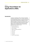
USER'S
Model No. 831.297160
Serial No.
The sedal number is found in the location
shown below. Write the serial number in
the space above for future reference,
_ll
E(_
SerialNumber
u
I['__l_llll
i
P
=llm.:"l_l _
1,4
E
_1_:_
HELPLINE!
1-800-72,6-6879
Ill]
NT"
_ 11,-I
MANUAL
TABLE
OF CONTENTS
IMPORTANT PRECAUTIONS
:
..
.................................................................
BEFORE YOU BEGIN ......................................................................
ASSEMBLY ................................................................................
OPERATION AND ADJUSTMENT
.............................................................
HOW TO FOLD AND MOVE THE TREADMILL
..................................................
TROUBLE-SHOOTING
.....................................................................
CONDITIONING GUIDELINES
...............................................................
ORDERING REPLACEMENT PARTS ..................................................
FULL 90 DAY WARRANTY
...........................................................
2
7
10
12
14
Back Cover
Back Cover
Note: An EXPLODED DRAWING and a PART LIST are attached to the center of this manual. Save the
EXPLODED DRAWING and PART LIST for future reference.
IMPORTANT
•
PRECAUTIONS
13. Never move the walking belt while the power
is turned off. Do not operate the treadmill if
" " ASSEMBLY on pages 5and 6, a
MOVE THE TREADMILL on
the power cord or p!ug is_damaged, or if the
treadmill is not W_rking I_l_opel:ly.(See B EFORE YOU BEGIN on page4 if the treadmill
is not workim
14. Never start the
standing
the handrails
•
while usin9 the treadmill.
Adjust ti_e s_a
fill smaii increments
avoid sudden ]U'm_s in
to
The decal shown below has been placed on your treadmill. If the decal is missing, or if it is not legible,
please call our toll-free HELPLINE to order a free replacement decal (see the back cover of this manual).
Apply the decal in the location shown.
BEFORE
YOU BEGIN
Thank you for selecting the LIFESTYLER* EXPANSE
600 treadmill. The EXPANSE 600 treadmill combines
advanced technology with innovative design to let you
enjoy an excellent form of cardiovascular exercise in
the convenience and privacy of your home. And when
you're not exercising, the unique EXPANSE 600 can
be folded up, requiring less than half the floor space of
ether treadmills.
For your benefit, read this manual carefully before
using the treadmill. If you have additional questions,
please call our toll-free HELPLINE at 1-800-736-6879,
Monday through Saturday, 7 a.m. until 7 p.m. Central
Time (excluding holidays). To help us assist you,
please note the product model number and serial nu,
her before calling. The model number of the treadmill
is 831.297160. The sedal number can be found on a
decal attached to the treadmill (see the front cover of
this manual for the location).
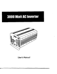
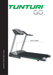
Before reading further, please review the drawing
below and fa.miliadze yourself with the parts that are
labeled.
Towel Rack
Water Bottle Holder
/ (Water Bottle is not
included)
Accessory Tray
Storage Latch--
Key c,p
Handrail
RIGHT SIDE
Upright
Walking Belt_.
Circuit
Cord
Rear Roller
Adjustment Bolt
4
BACK
Incline Leg
Cushioned-Walking Platform
for maximum exercise comfort
I
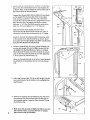
ASSEMBLY
=
Assembly requires two people. Set the treadmill in a cleared area and remove all packing materials° Do not
dispose of the packing materials until assembly is completed. Refer to the drawings below to identify the parts
used in assembly. Assembly requires the following tools: The included allen wrench
_ and your own
phillips screwdriver
_-====4_
and adjustable wrench _.
Base Screw/Latch Screw (13)-6
Handrail Bolt (15)-2
Handrail Washer (16)-2
Extension Leg Screw (34)-2
Handrail Screw (32)-2
1. With the help of a second person, carefully lay the
treadmill on its side. Insert one of the Extension Legs
(41) into the treadmill as shown. Make sure that the Base
Pad (36) is on the bottom of the Extension Leg. Attach
the Extension Leg with an Extension Leg Screw (34). Be
sure to push on the head of the Extension Leg Screw
while tightening it.
I1
73-q.,.j, 34
41
Attach the other Extension Leg (41) as described above.
14
With the help of a second person, carefully raise the
treadmill to the updght position so the Extension Legs
(41) are resting flat on the floor.
2. Refer to HOW TO LOWER THE TREADMILL
FOR USE
on page 11, Follow the instructions in step 2 to lower the
treadmill.
Position one of the Handrails (2) on the left Updght (14)
as shown. Thread a Handrail Bolt (15) with a Handrail
Washer (16) into the left Upright and the Handrail. Do not
tighten the Handrail Bolt yet. Tighten a Handrail Screw
(32) into the lower end of the Handrail. Be sure to push
on the head of the Handrail Screw while tightening it.
Next, tighten the Handrail Bolt (15).
2
With the help of ,_ second person, hold the _Console Base
(6) and the other Handrail (2) near the right Upright (14)
as shown. Note: It may be helpful to rest the other side of
the Console Base on the left Handrail.
3,
Connect the Console Wire Harness (88) to the two plugs
on the Updght Wire Harness (26). Refer to the upper
inset drawing. ,Locate the 7 1/2" Wire Ties (10) on the
Console Wire Harness (88) and the Upright Wire Harness
(26). Slide the Wire Ties against the plugs as shown,
Insert the 11 1/2" Wire Tie (55) through the holes in the
Wire Ties. Close and tighten the 11 1/2" Wire Tie.
Refer to the lower inset drawing. Insert the Wire
Harnesses (26, 88) into the Right Upright (14). Note: If
necessary, bend the Wire Harnesses into an %" shape.
Route the Console Wire Harness (88) through the notch
in the bracket on the right Handrail (2) as shown. Insert
the bracket into the right Upright (14), Make sure that the
Console Wire Harness is not pinched.
4.
Thread a Handrail Bolt (15) with a Handrail Washer (16)
into the right Upright (14) and the-_t
Handrail (2). Do
not tighten the Handrail Bolt yet. Tighten a Handrail
Screw (32) into the lower end of the Handrail. Be sure to
push on the head of the Handrail Screw while tightening
it. Next, tighten the Handrail Bolt (15).
16
Place the Console Base (6) on the left and right Handrails
(2). Attach the Console Base with four Console Screws
(13).
5. Attach the Storage Latch (12) to the lett Upright (!4) with
two Latch Screws (13). Be careful not to overtighten the
Latch Screws.
/
/
12
6. Remove the
the Adhesive
the indicated
the Adhesive
6
backing from the Adhesive C!ip (74). Press
Clip onto the Rear Roller Endcap (72) in
location. Press the Allen Wrench (73) into
Clip.
7. Make sure that all parts are tightened before you use
the treadmill. Note: To protect the floor or carpet,
place a mat under the treadmill.
73-_
o''"
74
OPERATION
THE PERFORMANT
AND ADJUSTMENT
LUBE
TM
WALKING
BELT
Your treadmill features a walking belt coated with
PERFORMANT LUBE TM, a high-performance lubricant.
IMPORTANT: Never apply silicone spray or other
substances
to the walking belt or the walking platform. Such substances will deteriorate the walking
belt and cause excessive wear.
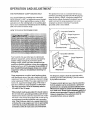
This product is for use on a nominal 120-volt circuit,
and has a grounding plug that looks like the plug illustrated in drawing 1 below. A temporary adapter that
looks like the adapter illustrated in drawing 2 may be
used to connect the surge suppressor to a 2-pole
receptacle as shown in drawing 2 if a propedy
grounded outlet is not available.
HOW TO PLUG IN THE POWER CORD
Grounded Outlet
Grounding Plug
2
-- Grounded Out_et Box
Your treadmill, like any other type of sophisticated
electronic equipment, can be seriously damaged by
sudden voltage changes in your home's power.
Voltage surges, spikes, and noise interference can
result from weather conditions or from other appliances
being turned on or off. To decrease the possibility of
your treadmill being damaged, always use a surge
suppressor with your treadmill (see drawing I at
the right).
Surge suppressors are sold at most hardware stores
and department stores. Use only a single-outlet surge
suppressor that is UL 1449 listed as a transient voltage
surge suppressor (TVSS). The surge suppressor must
have a UL suppressed voltage rating of 400 volts or
less and a minimum surge dissipation of 450 joules.
The surge suppressor must be electdcally rated for
120 volts AC and 15 amps.
This product must be grounded. If it should malfunction or break down, grounding provides a path of least
resistance for electric current to reduce the risk of electric shock. This product is equipped with a cord having
an equipment-grounding
conductor and a grounding
plug. Plug the power cord into a surge suppressor,
and plug the surge suppressor into an appropriate
outlet that is properly Installed and grounded In
accordance
with all local codes and ordinances.
Adapter
y
_
.
Surge Suppressor
Metal Screw
_
-,,.<
The temporary adapter should be used only until a
properly grounded outlet (drawing 1) can be installed
by a qualified electrician.
The green.colored rigid ear, lug, or the like extending
from the adapter must be connected to a permanent
ground such as a prapedy grounded outlet box cover.
.
Whenever the adapter is used it must be held in place
by a metal screw. Some 2-pole receptacle outlet box
covers are not grounded. Contact a qualified electrician to determine if the outlet box cover Is
grounded befo[e using an adapter,
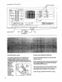
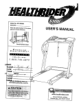
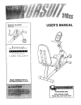
DIAGRAM
OF THE CONSOLE
,//
qTRAINIHG
ZONE
MonitorDisplays
_
HF_RT
RATE
30
TRAINING
,
ZONE
.
40
_
I_].1 h
,8o
.,
_11
.
milJ31
-. PPJ'!
SP£EO
CAL_ I FAT CALS
,
POWER
V
Speed Control /
BATTERY INSTALLATION
STEP BY STEP CONSOLE OPERATION
The console requires three "AA" batteries (not
included). Alkaline battedes are recommended.
To install batteries, open the battery cover under the
console as shown below. Press three batteries into the
If there is a thin sheet of clear film on the face of the
console, remove It.
battery compadment.
Make sure
that the negative (-)
ends of the
batteries are
touching the
spdngs.
Close the
battery cover.
8
Clip-
Before operating the console, make sure that the power
cord is properly plugged in. (See HOW TO PLUG IN
THE POWER CORD on page 7.)
Baffery
Cover
Next, step onto the foot rails of the treadmill. Find the
clip attached to the key (see the drawing above), and
slide the clip onto the waistband of your clothing.
Follow the steps on page 9 to operate the console.
_a_eries
.J
g
insert the key fully into the power
CALORIES/FAT CALORIES display--Thisdisplay shows the approximate numbers of
calories and fat calories
switch,
Inserting the key will
not turn on the disJ
plays. The displays will
turn on when the
ON/RESET button is
pressed or when the
I
walking belt is started.
Note: If you just installed batteries, the displays will already be on.
The displays can be
reset, if desired, by
pressing the ON/RESET
button.
Slide the speed control
down to the RESET
position. Note: Each
time the walking belt is
stopped, the speed
control must be moved
_
T_AIHtNG
ON / RESET
lie
_
ZONI
B
• ero_C
Wxt_-up
When you are finished exercising,
walking belt and remove the key.
stop the
Step onto the foot rails, stop the walking belt, and
remove the key from the console. Store the key in a
secure place. After the key is removed, the displays will turn off after about five min--utes.
Note: Any time that the walking belt is stopped
and no console buttons are pressed for five
minutes, the displays will automatically turn off
' in order to conserve the batteries.
k3
Start the walking belt.
After you have moved the speed control to the
RESET position, slowly slide it upward until the
walking belt begins to move at slow speed.
Carefully step onto the walking belt and begin exercising. Change the speed of the walking belt as desired by sliding the speed control.
To stop the walking belt, step onto the foot rails and
slide the speed control to the RESET position.
Follow your progress
|
petfo,_c,I
to the RESET position
before the walking belt
can be restarted.
B
CALS.I FAT CA£S_
you have burned. (See
FAT BURNING on page
14 for an explanation of fat calories.) Every seven
seconds, the display will change from one number
to the other. Arrows in the display will indicate
which number is currently shown.
Reset the speed control.
.
Arrows
with the monitor displays.
TIME display--This
display shows the total
time that you have
walked or run on the
treadmill.
DISTANCE display-This display shows the
total distance that you
have walked or run, in
miles.
SPEED display--This
display shows the speed
of the walking belt, in
miles per hour.
TIME
I IJ
,c:=,F,'l
Ju I
DISTANCE
I mr_t
Lf._IJ
"'. -I C I-t I
_7._tLf J
SPEED
HOW TO CHANGE THE INCLINE OF THE TREADMILL
The incline of the treadmill can be changed by raising
or lowering the back end. Before changing the Incline, remove the key and unplug the power cord.
rear roller
endcap
with both
hands.
Hold the
When the
back end
_.._
_"
of the
Roller Endcap /
In'line
treadmill is
In these locations
Leg
in the lowest position, the incline is about 10%. Raise the back end until it
clicks into position. (Note: It may be necessary to shake
the treadmill lightly so that it clicks.into position.) The incline will then be about 5%. Raise the back end again
until it clicks into position. The incline will then be about
3%. To lower the back end, first raise it past the highest
position, and then lower it. CAUTION: Before exercising, push on the back of the'll"eadmill to make sure
that the Incline legs are locked in position. Do not
place objects under the treadmill to change the Incline; change the incline only as described above.
HOW TO FOLD AND MOVE THE TREADMILL
HOW TO FOLD THE TF_EADMILL FOR STORAGE
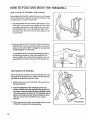
Before folding the treadmill, unplug the power cord. Caution:
You must be able to safely lift 45 pounds (20 kg) in order
to raise, lower, or move the treadmill.
1. Hold the treadmill with your hands in the locations shown
at the dght. To decrease the possibility of injury, bend
your legs and keep your back straight. As you raise
the treadmill, make sure to lift with your legs rather
than your back. Raise the treadmil{ about halfway to the
vertical position.
Move your right hand to the position shown and hold the
treadmill firmly. Raise the treadmill until the storage latch
closes over the catch: Make sure t_t the storage latch
is fully engaged over the catch.
.
To protect the floor or carpet from damage, place a
mat under the treadmill. Keep the treadmill out of
direct sunlight. Do not leave the treadmill in the storage position in temperatures
above 85 ° Fahrenheit.
I
HOW TO MOVE THE TREADMILL
Before moving the treadmill, convert the treadmill to the storage position as described above• Make sure that the storage latch is closed fully over the catch.
1. Hold the upper ends of the handrails. Race one foot on
the base as shown.
o
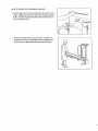
3.
10
Tilt the treadmill back until it rolls freely on the front
wheels. Carefully move the treadmill to the desired location. Never move the treadmill without tipping It back,
or the base pads may come off. To reduce the risk of
Injury, use extreme caution while moving the treadmill. Do not move the treadmill over an uneven
surface.
Place one foot on the base, and carefully lower the treadmill until it is resting in the storage position.
Base
els
HOW TO LOWER THE TREADMILL
FOR USE
1. Hold the upper end of the treadmill with your right hand as
shown. Using your left thumb, press the storage latch and
hold it. Pivot the treadmill until the frame and foot rail are
past the storage latch.
Unlatched
2. Hold the treadmill firmly with both hands, and lower the
treadmill to the floor. To decrease the possibility
of iniury, bend your legs and keep your back straight.
1;
TROUBLE-SHOOTING
Most treadmill problems can be solved by following the simple steps below. Find the symptom that
applies, and follow the steps listed. If further assistance is needed, call our toll-free HELPLINE at
1-800-736-6879, Monday through Saturday, 7 a.m. until 7 p.m. Central Time (excluding holidays).
1. SYMPTOM: THE POWER DOES NOT TURN ON
a. Make sure that the power cord is plugged into a surge suppressor, and that the surge suppressor is plugged
into a properly grounded outlet (see page 7). Use only a single-outlet surge suppressor that is UL 1449
listed as a transient voltage surge suppressor (TVSS). The surge suppressor must have a UL suppressed
voltage rating of 400 volts or less and a minimum surge dissipation of 450 joules. The surge suppressor
must be electrically rated for 120 volts AC and 15 amps.
b. After the power cord has been plugged in, make sure that the key is fully inserted into the console. See step
1 on page 9.
c. Check the circuit breaker located On the treadmill near the
power cord. If the switch protrudes as shown, the circuit
breaker has tdpped. To reset the circuit breaker, wait for five
minutes and then press the switch back in.
2. SYMPTOM: THE POWER TURNS OFF DURING USE
a. Check the circuit breaker located on the treadmill frame 'near the power cord (see 1. c. above). If the circuit
breaker has tripped, wait for five minutes and then press the switch back in.
b. Make sure that the power cord is plugged in.
c. EJemov_the key from the console. Reinsert the key fully into the console. See step 1 on page 9.
d. If the treadmill still will not run, please call our toll-free HELPLINE.
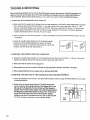
3. SYMPTOM: THE DISPLAYS OF THE CONSOLE
DO NOT FUNCTION PROPERLY
a. Check the batteries in the console. See BATi'ERY
of drained batteries.
INSTALLATION on page 8. Most problems are the result
b. Remove the six screws from the hood. Carefully remove the
hood. Locate the Reed Switch (86) and the Magnet (87) on the
left side of the Pulley (85). "rum the Pulley until the Magnet is
aligned with the Reed Switch. Make sure that the gap between
the Magnet and the Reed Switch Is about 1/8". If necessary,
loosen the Screw (35) and move the Reed Switch slightly.
Retighten the Screw. Re-attach the hood, and run the treadmill
for a few minutes to check for a correct speed reading.
12
1/8"
_i
35"_
86 "_
Top
View
:
83
_
_,
4. SYMPTOM: THE WALKING
BELT SLOWS WHEN _/ALKED
ON
a. Use only a UL-listed surge protector, rated at 15 amps, with a 14-gauge cord of five feet or less in length.
b. If the walking belt is overtightened, treadmill performance may
decrease and the walking belt may be permanently damaged.
Remove the key and UNPLUG THE POWER CORD. Using the
allen wrench, turn both rear roller adjustment bolts counterclockwise, 1/4 of a turn. When the walking belt is properly tightened,
you should be able to lift each side of the walking belt 2 to 3
inches off the walking platform. The center of the walking belt
should just touch the walking platform. Be careful to keep the
walking belt centered. Plug in the power cord, insert the key and
run the treadmill for a few minutes. Repeat until the walking belt
is propedy tightened.
b
Rear Roller Adjustment BoLts
c. If the walking belt still slows when walked on, please call our toll-free HELPLINE.
5. SYMPTOM: THE WALKING
BELT IS OFF-CENTER
WHEN WALKED
ON
a. If the walking belt has shifted to the left, first remove the key and
UNPLUG THE POWER CORD. Using the allen wrench, turn the
left rear roller adjustment bolt clockwise, and the right bolt counterclockwise, 1/4 of a turn each. Be careful not to overtighten the
walking belt. Plug in the power cord, insert the key and run the
treadmill for a few minutes. Repeat until the walking belt is centered.
b. if the walking belt has shifted to the right, first remove the key and UNPLUG THE POWER CORD. Using the allen wrench,
turn the left rear roller adjustment bolt counterclockwise, and the
dght bolt clockwise, 1/4 of a turn.each. Be careful not to overtighten the walking belt. Plug in the powe[ cord, insert the key
and fur! the treadmill for a few minutes. Repeat until the walking
belt is centered.
b
c. If the walking belt slips when walked on, first remove the key
and UNPLUG THE POWER CORD. Using the allen Wrench,
turn both rear roller adjustment bolts clockwise, 1/4 of a turn.
When the walking belt is correctly tightened, you should be able
to lift each side of the walking belt 2 to 3 inches off the walking
platform. The center of the walking belt should just touch the
walking platform. Be careful to keep the walking belt centered.
Plug in the power cord, insert the key and run the treadmill for a
few minutes. Repeat until the walking belt is properly tightened.
6. SYMPTOM: THE INCLINE SYSTEM STICKS
a. Raise the treadmill to the storage position. See HOWTO FOLD THE TREADMILL
10. Pivot the incline leg several times to break in the incline system.
FOR STORAGE on page
13
CONDITIONING
GUIDELINES
training zone. It may also be helpful to set the speed
control on the console to FAT BURN to help you mai_
tain the proper intensity level. (See page 9.)
Aerobic
The following guidelines will help you to plan your exercise program. Remember--these
are general guidelines only. For more detailed exercise information, obtain a reputable book or consult your physician.
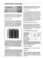
EXERCISE INTENSITY
Whether your goal is to burn fat or to strengthen your
cardiovascular system, the key to achieving the desired results is to exercise with the proper intensity.
The proper intensity level can be found.=by using your
heart rate as a guide. The chart belo_ows
recommended heart rates for fat burning and aerobic exercise. (This chart is also found on the console.)
HEART RATE TRAINING ZONE
II,_!l[_|:l'J,'_ll-
_
Exercise
[f your goal is to strengthen your cardiovascular system, your exercise must be "aerobic." Aerobic exercise
is activity that requires large amounts of oxygen for
prolonged periods of time. This increases the demand
on the heart to pump blood to the muscles, and on the
lungs to oxygenate the blood. For aerobic exercise,
adjust the speed and incline of the treadmill until your
heart ;ate is near the highest number in your training
zone. It may also be helpful to set the speed control on
the console to AEROBIC to help you maintain the
proper intensity level. (See page 9.)
High Performance
Athletic Conditioning
If your goal is high performance athletic conditioning,
set the speed control on the console to PERFORMANCE to help you maintain the proper intensity level.
(See page 9.)'Note: During the first few weeks of your
exercise program, keep your heart rate near the low
end of your training zone.
J r_h):4hf;M
HOW TO MEASURE YOUR HEART RATE
20 _eJ,
( 2O
30
'.-ID_t
".'1
;I
lot.
_"
k_
40
( 40
(.50
I Dbk
P:l*- --
i.l_
F'+
_1.
_f,
_1'
( 60
( 70
D(e_
I_-
rr,
_l L
FI'
kJ_
(_o
_Isi--_
--
_,_-:._ _t.
-
To find the proper heart rate for you, first find your age
on the left side of the chart (ages are rounded off to
the nearest ten years). Next, find the three numbers to
the right of your age, The three numbers are your
"trainingzone." The lower two numbers are recommended heart rates for fat burning; the higher number
is the recommended heart rate for aerobic exercise.
Fat Burning
14
To burn fat effectively, you must exercise at a relatively
low intensity level for a sustained period of time. Dudng
the first few minutes of exercise, your body uses easily
accessible carbohydrate calories for energy. Only after
the first few minutes does your body begin to use
stored fat calories for energy. If your goal is to bum fat,
adjust the speed and incline of the treadmill until your
heart rate is near one of the lower two numbers in your
To measure your
heart rate, stop ex-_....____
... /_
erdsing and place
two fingers on
your wrist as
shown. Take a sixsecond heartbeat
count, and multiply
the result by ten to
find your heart
rate. (A six-second count is used because your beart
.rate drops quickly when you stop exercising.) If your
heart rate is too high or too'low, adjust the speed or incline of the treadmill accordingly.
WORKOUT
GUIDELINES
A well-rounded workout includes the following three
important parts:
A Warm-up
Start each workout with 5 to 10 minutes of stretchin
and light exercise (see SUGGESTED STRETCHES ,.
page 15). A proper warm-up increases your body
temperature, heart rate, and circulation in preparation
for exercise.
Training
Zone Exercise
After warming up, increase the intensity of your exercise until your pulse is in your training zone for 20 to
60 minutes. (During the first few weeks of your exercise program, do not keep your pulse in your training
zone for longer than 20 minutes.) Breathe regularly
and deeply as you exercise--never hold your breath.
t_ cool down. This will incre_ase the flexibility of your
muscles and will help to prevent post-e:<ercise problems.
Exercise
Frequency
To maintain or improve your condition, complete three
workouts each week, with at least one day of rest between workouts. After a few months, you may complete up to five workouts each week if desired.
A Cool-down
Finish each workout with 5 to 10 minutes of stretching
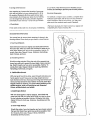
SUGGESTED
The key to success is to make exercise a regular and
enjoyable part of your everyday life.
STRETCHES
The correct form for several basic stretches is shown in the
drawings below. Move slowly as you stretch-never
bounce.
1. Toe Touch Stretch
Stand with your knees bent slightly and slowly bend forward
from your hips. Allow your back and shoulders to relax as you
reach down toward your toes as far as possible. Hold for 15
counts, then relax. Repeat 3 times, Stretches: Hamstrings,
back of knees, and back.
2. Hamstring
2
Stretch
Sit with one leg extended. Bring the sole of the opposite foot
toward you and rest it against the inner thigh of your extended
leg. Reach toward your toes as far as possible. Hold for 15
counts, then relax. Repeat 3 times for each leg. Stretches:
Hamstdngs, lower back, and groin.
3. Calf/AchiUes
3
Stretch
With one leg in front of the other, reach forward and place your
hands against a wall Keep your back leg straight and your
back foot fiat on the floor. Bend your front leg, lean forward and
move your hips toward the wall. Hold for 15 counts, then relax.
Repeat 3 times for each leg. To cause further stretching of the
achilles tendons, bend your back leg as well. Stretches:
Calves, achilles tendons, and ankles.
4. Quadriceps Stretch
With one hand against a wall for balance, reach back and
grasp one foot with your other hand. Bdng your heel as close
to your buttocks as possible. Hold for 15 counts, then relax.
Repeat 3 times for both legs. Stretches: Quadriceps and hip
muscles.
5. inner Thigh Stretch
Sit with the soles of your feet together and your knees outward.
Pull your feet toward your groin area as far as possible. Hold
for 15 counts, then relax. Repeat 3 times. Stretches:
Quaddceps and hip muscles.
1.'
iii
i i
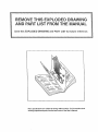
REMOVE THIS EXPLODED DRAWING
AND PART LIST FROM THE MANUAL
Save this EXPLODED
DRAWING
and PART LIST for future
reference.
IIII
Note: Specifications are subject to change without notice. For information
erdedng replacement parts, see the back cover of the User's Manual.
about
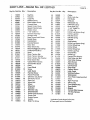
PART LIST ---Model
No. 831.297160
Key No. Part No. Qty.. ". Description
1
2
3
4
5
6
7
8
9
10
11"
12
13
14
15
16
17
18
11"
20
21
22
23
24
25
26
27
28
29
30
31
32
33
34
35
36
37
38
39
40
41
42
43
44
119038
137652
125708
130459
100691
137606
131161
128093
129639
132315
139758
137944
013576
137660
013505
014063
1"18016
012149
139794
126747
139792
013547
122812
014117
107503
139788
120630
139760
137_4-3013300
138141
131826
013581
013484
133867
126650
130868
132314
119425
137857
137387
109382
124695
124669
1
1
2
1
4
1
1
1
1
2
1
1
7
1
2
7
1
1
1
1
1
3
1
1
1
1
2
1
1
12
1
2
2
2
29
6
2
2
7
1
2
1
1
1
45
46
47
137625
139761
138853
2
4
16
Key/Clip
Handrail
Cage Nut
Ratchet Screw
Rear Isolator Screw
Console Base
Speed Control Knob
Speed Potentiometer
Battery Cover
7 1/2" Cable Tie
Console Assembly
Storage Latch
Base Screw/Latch Screw
Ulqdght Base
Handrail Bolt
Handrail Washer
Motor Belt
Motor Swivel Nut
MotodPufle3_lywheel/Fan
Pulley/Flywheel/Fan
Motor
Motor Te=nsion Bolt
Motor Tension Washer
Motor Tension Star Washer
Motor Swivel Bolt
Upright Wire Harness
Ground Wire Screw
Hood
Hood Shield
Screw
Latch Decal
Handrail Screw
Frame Pivot Bolt
Extension Leg Screw
Electronics Screw
Base Pad
Wheel Bolt
Wheel
Wheel Nut
Controller
Extension Leg
Circuit Breaker
Power Cord Grommet
Power Cord
Upright Spacer
Isolator
Belfy Pan Screw
-R0697B
Key No. Part No. Qty.
48
49
50
51
52
53
54
55
56
57
56
59
60
61
62
63
64
65
66.
67
68
69
70
71
72
73
74
75
76
77
78
79
80
81
82
83
84
85
86
87
88
#
#
130993
120867
109265
137874
116926
116927
137873
132383
016057
128271
013578
108080
124565
131240
139763
134353
117806
137731
117806
137671
114261
137634
014132
105444
137632
128457
0160_8
139764
139765
128272
138732
139787
137956
112609
139767
139768
131090
139786
138680
100498
139790
103823
137651
1
1
2
1
1
1
1
1
4
1
1
2
1
1
2
2
2
2
2
1
1
1
2
2
1
1
1
1
1
4
1
1
1
1
1
1
1
1
1
1
1
1
1
Description
Choke
Motor Lock Nut
Belt Guide
Belly pan
Releasable Tie
Cable Tie Clamp
Motor Belly pan
11 1/2" Cable Tie
8" Cable Tie
Incline Leg Spacer (long)
Incline Leg Bolt
Ratchet Screw
Ratchet Spring
Ratchet
Solid Isolator
Incline Leg Spacer (long)
Incline Wheel Bolt
Incline Wheel
Incline Wheel Nut
Incline Leg Plate
Ground Wire
Incline Leg
Upright Pivot Washer
Rear Roller Adj. Bolt
Rear Roller Endcap
Allen Wrench
Adhesive Clip
Left Foot Rail
Rear Roller
Platform Screw
Latch Catch
Walking Platform
Walking Belt
Front Roller Adjustment Bolt
Shock
Right Foot Rail
Sensor Clip
Front Roller/Pulley
Reed Switch
"- Magnet
Console Wire Hamess
14" Wire Harness
Manual
* Includes all parts shown in the box
# These parts are not illustrated
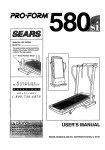
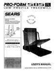
EXPLODED:
DRAWING--Model
I
No. 831.297160.
.R0697B
6
÷J°
J
16
i
'8
28
19"
29
*
q
35
3
35
35
35
3_,_
I
35
81
.J
8O
\
34
J
79
44
33 ¸
]
75
74
..
51
_"_47
72
76
_47
...
7O
_L
4
41
_-_
35
48
36
31
8--.-47
59
4
71
46
61
"-._--57
54
64
3O
"_.
The model number and serial number of your LIFESTYLER ®
EXPANSE 600 treadmill are listed on a decal attached to the frame.
See the front cover of this manual to find the location of the decal.
Model No. 831.297160
All replacement parts are available for immediate purchase or
special order when you visit your nearest SEARS Service Center.
To request service or to order parts by telephone, call the toll-free
numbers listed at the left.
QUESTIONS?
If you find that:
• you need help assembling or
operating the LIFESTYLER ®
EXPANSE 600 TL treadmill
• a part is missing
• or you need to schedule repair :
service
When requesting help or service, or ordering parts, please be
prepared to provide the following information:
• The NAME OF THE PRODUCT (LIFESTYLER ®EXPANSE 600
treadmill)
• The MODEL NUMBER OF THE PRODUCT (831.297160)
call our toll-free HELPLINE
1-800-736-6879
Monday-Saturday, 7 am-7 pm
Central Time (excluding holidays)
• The PART NUMBER OF THE PART (see the EXPLODED
DRAWING and PART LIST included in this manual)
• The DESCRIPTION OF THE PART (see the EXPLODED
DRAWING and PART LIS.T included in this manual).
REPLACEMENT
PARTS
If parts become worn and need
to be repla_ed, call the following
toll-free number
1-800-FON-PART
(1-800:366-7278)
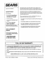
FULL 90 DAY WARRANTY
.
For 90 days from the date of purchase, if failure occurs due to defect in material or workmanship in this
SEARS TREADMILL EXERCISER, contact the nearest SEARS Service Center throughout the United
States and SEARS will repair or replace the TREADMILL EXERCISER, free of charge.
This warranty does not apply when the "I'READMILL
poses.
EXERCISER
is used commercially or for rental pur-
This warranty gives you specific legal rights, and you may also have other rights which vary from state
ta state.SEARS, ROEBUCK AND CO., DEPT. 817WA, HOFFMAN
ESTATES, IL 60179
ii
Part No. 137651 G02040AC
RO697B
Printed in USA © 1997 Sears, Roebuck and Co.