1
INSTALLER"
LEAVE
THESE
INS TRUG
TIONS
WITH
THE APPLIANCE
INSTALLATION MANUAL
Gas 24-inch Built-ln Ovens
PLEASE
THE MANUAL
KEEP THIS MANUAL
IS INTENDED
FOR FUTURE
REFERENCE
TO ASSIST IN THE INITIALINSTALLATION AND ADJUSTMENTS
OF THE RANGE
Clearance Dimensions
Only qualified personnel should
install or service this range.
Read "Safety Instructions" in the
Use & Care book before using
range.
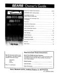
For complete information in regard to the installation of
wall ovens and clearances to combustible wall above the
cooking top see the installation drawings.
A WIRING DIAGRAM IS ENCLOSED IN THE
ENVELOPE WITH THIS BOOKLET; ALSO THERE IS A
DIAGRAM GLUED TO THE UNIT, BEHIND CONTROL
PANEL.
CAUTION: SOME CABINETS
Improper installation, adjustment,
alteration, service, maintenance or
use of range can result in serious
injury or property damage.
AND BUILDING
MATERIALS ARE NOT DESIGNED TO WITHSTAND THE HEAT PRODUCED BY THE
NORMAL SAFE OPERATION OF A LISTED
APPLIANCE. DIS- COLOATION OR DAMAGE,
SUCH AS DELAMINATION,
MAY OCCUR.
Your range may not be equipped with some of the features referred to in this
manual.
8101 P590-60
(o8-o5-o1)
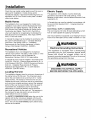
Installation Drawings
PROVIDE
SLOT
120 VOLT GROUNDED
ELECTRICAL
OUTLET
IN THIS
AREA
11
FRONT
OF
CABI
MIN
OVEN SUPPLIED
WITH
112"
NPT FEMALE
INLET
ON REGULATOR.
62"
WITH
A 3
PRONG CORD
4"
RECOMMENDED
AREA FOR ELECTRICAL
CONNECTION
45-318"
I!
IDE HOLE IN
THIS
GENERAL
AREA
FOR CONNECTING
TO
112"
DIAMETER
PIPE
FITTING
I
I
I
I
I
I
I
I
I
I
I
I
46-5/16"
COMPLETE
FLOC
IS RECOMMENDED
TO PREVENT
UNUSUAL
DRAFTS.
14"
MIN.
HEIGHT
URE OVEN TO CABINET
THROUGH
HOLES PROVIDED
IN TRIM.
FOUR
SCREWS SHIPPED
WITH UNIT.
FIGURE
I
24" GAS WALL OVENS
"A"
UPPER OVEN
MODEL
DOUBL_
OVEN
3VEN
LOWER
OVEN OR BROILER
"B"
OVEN FRAME
SIZE
CUTOUT
DIMENSIONS
WIDTH
HEIGHT
DEPTH
WIDTH
HEIGHT
DEPTH
WIDTH
HEIGHT
WIDTH
HEIGHT
"A"
DEPTH
18"
14"
!9"
18"
12"
19"
23 7/8"
46 5/16"
22"
45 318"
24"
18"
14"
19"
18"
6.25"
19"
23 718"
39 114"
22"
38"
24"
WIT}[
_I{on,ER
-2-
Installation
Check the oven model number plate to see if the oven is
approved for installation in mobile homes and/or
recreational vehicles. If approved the following items are
applicable. NOTE: Oven model number plate is located
under broiler bottom.
Electric Supply
The appliance, when installed, must be electrically
grounded in accordance with local codes or, in the
absence of local codes, with the National Electrical Code,
ANSI/NFPA 70.
Mobile Homes
In Canada the oven must be installed in accordance with
the current CSA Standard C22.1 - Canadian Electrical
Code Part 1.
The installation of an oven designed for mobile home
installation must conform with the Manufactured Home
Construction and Safety Standard, Title 24 CFR, Part
3280 (formerly the Federal Standard for Mobile Home
Construction and Safety, Title 24 HUD, (Part 280) or,
when such standard is not applicable, the Standard for
Manufactured Home Installations, ANSI A225.1/NFPA
501A, or with local codes.
ELECTRICAL
CONNECTION:
The oven requires 120 volts, 60 cycle alternating current
from an outlet capable of supplying 15 amperes.
User may experience occasional circuit tripping if Ground
Fault Circuit Interrupter (GFCl) outlet or breaker is in use.
In Canada the range must be installed in accordance with
the current CSA Standard C22.1 - Canadian Electrical
Code Part 1 and Section Z240.4.1 - Installation
Requirements for Gas Burning Appliances in Mobile
Homes (CSA Standard CAN/CSA - Z240MH).
Recreational
SUPPLY
, WARNING
Electrical Grounding
Vehicles
Instructions
This appliance
is equipped
with a (three-prong)
grounding
plug for your protection
against shock
hazard and should be plugged
directly into a
properly grounded receptacle. Do not cut or remove
the grounding prong from this plug.
The installation of an oven designed for recreational
vehicles must conform with state or other codes or, in the
absence of such codes, with the Standard for
Recreational Vehicles, ANSI A119.2-latest edition.
In Canada the oven must be installed in accordance with
CAN/CSA - Z240.6.2 - Electrical Requirements for R.V.'s
(CSA Standard CAN/CSA - Z240 RV Series) and Section
Z240.4.2 - Installation Requirements for Propane
Appliances and Equipment in R.V.'s (CSA Standard
CAN/CSA - Z240 RV Series).
I WARNING
DISCONNECT
ELECTRICAL
SUPPLY
BEFORE SERVICING THE APPLIANCE.
Locating The Unit
The installation diagram gives the minimum dimensions of
the cabinet cut-out for the oven. The dimensions given
are for the oven bottom to be a minimum of 14" inches
above the floor. The recess in which the oven is to be
installed should have a solid floor and be so constructed
as to provide a complete enclosure around the recessed
portion of the oven to prevent drafts which may result in
inconsistent and unsatisfactory burner and baking
performance, it should be perfectly level to provide a
solid, level foundation for the oven unit. The openings in
the enclosure for gas and electric service should be
sealed before the oven is installed.
For SAFETY CONSIDERATIONS fasten the oven to the
cabinet with the four (4) screws (shipped with the unit)
through the holes in the trim behind the oven and broiler
doors. The unit should be leveled properly before being
secured to the cabinet.
-3-
Connecting The Oven
Gas Supply
Installation of this oven must conform with local codes or,
in the absence of local codes, with the National Fuel Gas
Code, ANSI Z223.1-1atest edition.
or water). Dirt, etc. in the supply lines can work its way
into the range manifold and in turn cause failure of the
gas valves or controls and clog burners.
In Canada the oven must be installed in accordance with
the current CGA Standard CAN/CGA-B149 - Installation
Codes for Gas Burning Appliances and Equipment and/or
local codes.
CAUTION: DO NOT LIFT OR MOVE THE WALL
OVEN BY THE DOOR HANDLES.
In The Commonwealth
C.
Of Massachusetts
d.
This product must be installed by a licensed plumber or
gas fitter when installed within the Commonwealth of
Massachusetts.
e.
Turn off main gas valve at meter.
Before connecting the unit, apply pipe thread
compound approved for LPG to all threads.
A "T" handle type manual gas valve must be installed in
the gas supply line to this appliance.
Connect unit to gas supply. Use a backup wrench
when pulling on end of regulator.
A flexible gas connector, when used must not exceed a
length of three (3) feet / 36 inches.
CAUTION: MAKE SURE THE CONNECTION DOES
NOT SHIFT THE REGULATOR PIPE OUT OF
POSITION.
g.
GAS SUPPLY CONNECTION:
A QUALIFIED SERVICEMAN OR GAS APPLIANCE
INSTALLER MUST MAKE THE GAS SUPPLY
CONNECTION. Leak testing of the appliance shall be
conducted by the installer according to the
instructions given below in section h.
Turn on main gas valve at meter, and relight pilots at
other gas appliances.
h. Apply a non-corrosive leak detection fluid to all joints
and fittings in the gas connection between the supply
line shut-off valve and the range. Include gas fittings
and joints in the range if connections were disturbed
during installation. Check for leaks! Bubbles appearing
around fittings and connections will indicate a leak. tf a
leak appears, turn off supply line gas shut-off valve,
tighten connections, turn on the supply line gas shut
off valve, and retest for leaks.
NATURAL GAS SUPPLY LINE MUST HAVE A
NATURAL GAS SERVICE REGULATOR. INLET
PRESSURE TO THIS APPLIANCE SHOULD BE
REDUCED TO A MAXIMUM OF 14 INCHES WATER
COLUMN (0.5 POUNDS PER SQUARE INCH (P.S.I.)
LIQUIFtED PETROLEUM (L.P.)/PROPANE GAS
SUPPLY LINE MUST HAVE A LP. GAS PRESSURE
REGULATOR. INLET PRESSURES IN EXCESS OF 0.5
P.S.I. CAN DAMAGE THE APPLIANCE PRESSURE
REGULATOR AND OTHER GAS COMPONENTS IN
THIS APPLIANCE AND CAN RESULT IN A GAS LEAK.
a.
Turn off all 3ilots and main gas valve of other gas
appliances.
CAUTION:
FLAME.
NEVER CHECK FOR LEAKS WITH A
WHEN LEAK CHECK IS COMPLETE,
ALL RESIDUE.
WIPE OFF
Adjust burner air shutter to the widest opening that will
not cause the flame to lift or blow off the burner when
cold.
A GAS CUTOFF VALVE SHOULD BE PUT IN AN
ACCESSIBLE LOCATION IN THE SUPPLY LINE
AHEAD OF THE UNIT, FOR TURNING ON AND
TURNING OFF GAS SUPPLY. If the unit is to be
connected to house piping with flexible or semi-rigid
metal connectors for gas appliances, CONNECTOR
NUTS MUST NOT BE CONNECTED DIRECTLY TO
PIPE THREADS. THE CONNECTOR MUST BE
INSTALLED WITH ADAPTORS PROVIDED, WITH
THE CONNECTOR.
BEFORE LIGHTING ANY BURNER, SEE THAT ALL
PACKING MATERIALS HAVE BEEN REMOVED
FROM THE UNITS.
WARNING
Gas leaks may occur in your system and result in a
dangerous situation. Gas leaks may not be detected by
smell alone. Gas suppliers recommend you purchase and
install an UL approved gas detector. Install and use in
accordance with the manufacturer's instructions.
b. The house piping and/or oven connector used to
connect the oven to the main gas supply must be
clean, free of metal shavings, rust, dirt and liquids (oil
-4-
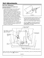
Unit Adjustments
Wall Oven Adjustment
ELECTRIC IGNITION - BAKE BURNER WITH
ELECTRIC GLOW BAR
a. The bake burner is equipped with an electric control
system as well as an electric oven burner ignitor
(figure 2). This control system requires NO
adjustment. To operate, turn thermostat knob to any
temperature setting or to broil. Current will flow to the
ignitor. It will "glow" similar to a light bulb. (This glow
may be reflected into the oven through the openings in
the oven bottom). When the ignitor has reached a
temperature sufficient to ignite gas, the electrically
controlled oven valve will open and flame will appear
at the oven burner. There is a time lapse from 30 to 45
seconds after the thermostat is turned ON before
flame appears at the oven burner. When the oven has
reached the dial setting, the glowing ignitor will go
OFF. The burner flame will go "out" in 20 to 30
seconds after the ignitor goes "OFF". To maintain any
given oven temperature this cycle will continue as long
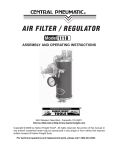
as the dial is at the given temperature. Figure 3 is an
illustration of a typical range.
FIGURE 2
b. In case servicing should become necessary, a manual
gas valve to shut off the gas to the oven burner is
supplied between the gas regulator and the oven
burner valve, tt is located at the front of the oven
bottom or on right rear of gas regulator. See figure 3.
c. The oven CANNOT be used during periods of
power outage. In case of power failure, turn the
thermostat to the OFF position.
PRESSURE
REGUALTOR
GAS SUPPLY PIPING
(NOT SUPPLIED
BY
MANUFACTURER)
ICAL
DISCONNECT
MANIFOLDPRESSURE
TAP
SER
PLATE
NUAL OVEN VALVE(SHOULD SERVICE EVER BECOME NECESSARY)
WHEN THE INSTALLER HAS COMPLETED INSTALLATION
SHUT-OFF VALVE IN THE "ON"
POSITION.
OF APPLIANCE,
FIGURE 3
-5-
LEAVE THE APPLIANCE
MANUAL
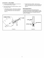
AIR SHUTTER
- OVEN BURNER
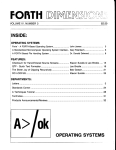
a. The approximate length of the flame of oven burner is
a 1/2 inch distinct blue flame, figure 4.
.
b. Oven burner flame can be checked as follows, without
burner baffle in place:
High Altitude
1. Yellow flame on burner - open burner air shutter to
the widest opening that will not cause the flame to
lift or blow off the burner when cold. (See #2 on
figure 5.)
BURNER
Distinct blue flame but lifting - close burner air
shutter to the point where it will not cause the flame
to lift or blow off the burner when cold. (See #2 on
figure 5.)
Notice
The specified gas burner ratings typically apply to
elevations up to 2000 feet. For higher altitudes, the rates
may need to be reduced to achieve satisfactory operation.
A local certified gas servicer will be able to advise if a
reduction is necessary.
BAFFLE
1/2" FLAME
LOCK SCREW
3
AIR SHUTTER
2
ORIFICE
FIGURE 4
HO
FIGURE 5
-6-
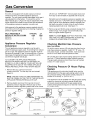
Gas Conversion
General
All ovens are equipped with double coaxial (universal)
orifices and with a convertible appliance pressure
regulator. The unit model number plate states which gas it
was adjusted for at the factory. To convert the unit to
either Natural gas or LP gas will require adjustment of the
orifice hood and air shutter on the burner and adjustment
of the appliance pressure regulator converter cap.
off with nut). "IMPORTANT" remove plastic dust cover
from cap nut and reinstall on opposite side of cap nut.
Reinstall cap nut to appliance pressure regulator and
replace dust cover. "CAUTION" be sure marking for the
type of gas to which appliance pressure regulator has
just been converted is visible in top of cap nut before
replacing plastic dust cover. (See figure 7.)
Inlet pressure to the appliance pressure regulator should
be as follows for both operation and checking of appliance
pressure regulator setting:
INLET PRESSURE IN
INCHES OF WATER COLUMN
Minimum
Maximum
Appliance Pressure
Conversion
NATURAL
GAS
5
14
.
LP
GAS
11
14
NOTE: PLUNGER MUST SNAP INTO POSITION; THE
GAS TYPE YOU ARE CONVERTING TO MUST BE
VISIBLE ON LOWER SIDE OF PLUNGER.
Regulator
Checking
Gas Pressure
On built-in ovens, remove 1/8 inch pipe plug from front or
side of gas pressure regulator, install 1/8" "B" valve, 1/8
inch piece of pipe, connect manometer, make sure main
burner is on to obtain accurate pressure check.
Be sure the gas supply (house piping) pressure is at least
one inch (1 ") above specified range manifold pressure.
The gas supply pressure should never be over fourteen
inches (14") water column.
TO CONVERT THE APPLIANCE PRESSURE
REGULATOR FROM ONE GAS TO ANOTHER, DO
EITHER (1), (2) OR (3) BELOW: YOUR UNIT WILL BE
EQUIPPED WITH ONE OF THE THREE APPLIANCE
PRESSURE REGULATOR TYPES SHOWN BELOW.
Checking
System
1. Remove the cap, push down and turn
counter-clockwise. Turn the cap over and reinstall
(figure 6).
Pressure
Of House
Piping
The appliance and its individual shutoff valve must be
disconnected from the gas supply piping system during
any pressure testing of that system at test pressures in
excess of 1/2 Ibs./sq. in. (13.8 in. W.C.).
NOTE: THE GAS TYPE YOU ARE CONVERTING TO
MUST BE VISIBLE ON THE TOP OF THE INSTALLED
APPLIANCE PRESSURE REGULATOR CAP.
The appliance must be isolated from the gas supply piping
system by closing its individual manual shutoff valve
during any pressure testing of the gas supply piping
system at test pressures equal to or less than 1/2 Ibs./sq.
in. (13.8 in. W.C.).
2. Remove plastic dust cover from cap nut on top of
appliance pressure regulator. Remove cap nut from
appliance pressure regulator (plastic dust cover comes
OO_ f_(
Manifold
BUILT-IN OVENS:
The unit appliance pressure regulator must be set to
match the type gas supply used. If converting from natural
gas to LP gas, the appliance pressure regulator must be
converted to regulate LP gas. If converting from LP gas to
natural gas, the appliance pressure regulator must be
converted to regulate natural gas.
LPG
Remove cap and forcibly snap out plastic plunger from
bottom of cap. Turn plunger over and forcibly snap
back in original location (figure 8).
_ONAT
C
L.P.
POSITION
,/
ART
_
A219-740
OVEN MANIFOLD
PRESSURETAP
FIGURE 6
FIGURE 7
GAS _
j_
FOR SOME OVEN
MODELS
FIGURE 8
-7-
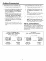
Orifice Conversion
1.
FROM NATURAL GAS TO LP/PROPANE GAS:
a.
b.
2,
Change the appliance pressure regulator from
natural to LP setting. (See figure 6, 7 or 8).
a.
b.
Screw the burner orifice hoods down tight against
the pins. (See figure 9B). Use care to not over
tighten. Over tightening can damage the coaxial
pin inside the orifice hood.
GAS TO NATURAL GAS:
Change the appliance pressure regulator from LP
to natural setting. (See figure 6, 7 or 8).
Screw the burner orifice hoods away from the
pins. (See figure 9A). Approximately 1 1/2 to 2
turns.
NOTE: On units using Eaton Oven Safety Valve,
screw the burner orifice hoods away from pin (see
figure 9C). Approximately 1 1/2 to 2 turns.
NOTE: On units using Eaton Oven Safety Valve,
screw the valve orifice hood down tight against
the valve body. (See figure 9D). It is important
that the hood be turned down as far as it can go
to insure that complete conversion has occurred.
C.
FROM LP/PROPANE
Adjust burner air shutter to the widest opening
that will not cause the flame to lift or blow off the
burner when cold.
Adjust burner air shutter to the widest opening
that will not cause the flame to lift or blow off the
burner when cold.
NOTE: Correctly adjusted sealed burners, the
flame will lift or blow without a pot over the burner.
These should be adjusted with a pot in place.
NOTE: Correctly adjusted sealed burners, can
have flames that will lift or blow without a pot over
the burner. These should be adjusted with a pot in
place.
FOR ALL TOP BURNER AND
OVEN SAFETY VALVE CONVERSION
(EXCEPT EATON VALVE)
SERVICE
- PARTS
INFORMATION
WHEN YOUR RANGE REQUIRES SERVICE OR
REPLACEMENT PARTS, CONTACT YOUR DEALER OR
AUTHORIZED SERVICE AGENCY. PLEASE GIVE THE
COMPLETE MODEL AND SERIAL NUMBERS OF THE
RANGE WHICH IS LOCATED ON THE RANGE MODEL
NUMBER PLATE.
FOR EATON
OVEN SAFETY VALVE CONVERSION
FECE HOOD
ART
FIGURE 9A
NATURAL GAS
SETTING
FIGURE 9B
LP GAS
SETTING
FIGURE 9C
NATURAL GAS
SETTING
-8-
I_
9219-983-0
FIGURE 9D
LP GAS
SETTING