1
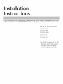
Installation
Instr ct"
Ifgou have questions,
call1.800.GE.Cares
{1.800.423.2737}
orvisit
our websiteatGEAppliances.cominthe
UnitedStates.InCanada, call1.800.561.3344
orvisit
www.GEAppliances.ca.
15" Built-In
Compactors
GCG1580 SS
GCG1500 BB
GCG1500 WW
GCG1700 II*
ZCGS150 SS
ZCGP150 II*
*For ZCGP150 II and GCG1700 II,
also refer to the instructions
provided
on the template
packed with those
models.
Safety Information
BEFORE YOU BEGIN
Read these instructions
carefullg.
• IMPORTANT- savethese
local inspector's
completelg
instructions
WARNING!
and
for
Do not allow items to fall or collect behind the
compactor. Failure to follow this instruction
could result in a fire.
use.
IMPORTANT- Observe all governing codes
and ordinances.
• Note to Installer - Be sure to leave these
instructions with the Consumer.
•
Note to Consumer - Keep these instructions with
gour Owner's Manual for future reference.
• Skill Level - Installation of this appliance requires
basic mechanical and electrical skills.
Completion time - 1 hour.
Proper installation is the responsibilitg
installer.
CAUTION:
For personal safetLl, remove house fuse or open
circuit breaker before beginning installation to
avoid severe or fatal shock injurg.
While performing installations described in this
book, safetg glasses or goggles should be
worn.
of the
Product failure due to improper installation is not
covered under the Warrantg. See Owner's Manual
for warrantg information.
IMPORTANT
• This compactor is for household use onlLl.
• Use this compactor onlLl for its intended purpose.
• This compactor is designed for BUILT-IN
installations ONLY.
CONTENTS
Design Information
Models Available ....................................................................
3
Product Dimensions and Clearances ..........................
3
Tools Required ........................................................................
3
Parts Supplied ........................................................................
3
Advance Planning
Clearances ................................................................................
4
Models with a Custom Drawer Panel ..........................
4
Installation
Preparation
Electrical Requirements
....................................................
5
Grounding Requirements ..................................................
5
Unpacking the Compactor ................................................
6
Leveling the Compactor ......................................................
7
Adjusting the Retaining Bracket ....................................
7
Adjusting the Base Toekick ................................................
7
Installation
Instructions
Position the Compactor under the Countertop ......8
Attach the Compactor to the Countertop ..................8
Reinstall the Compactor Drawer ....................................
9
Installation of the Trash Bag Caddg ............................
9
Finalize Installation ................................................................
9
Design Information
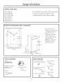
MODELS AVAILABLE
GCG1580 SS
*For ZCGP150 II and GCG1700 II, also refer
GCG1500 BB
to the instructions
provided on the
template packed with those models.
GCG1500 WW
GCG1700 I1"
ZCGS150 SS
ZCGP150 I1"
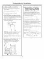
PRODUCT DIMENSIONS
AND CLEARANCES
• Allow 23" (58.4 cm)
clearance at the front for
24"
(61 cm)
min.
a full drawer opening.
• Allow 6" (15.2 cm)
15"
(38.1cm)
min.
clearance on the right
side to the nearest
vertical wall or cabinet
34" (86.4cm)
to
35" (88.9cm)
for bag removal.
• Note: This compactor
designed for built-in
applications onlg.
33-3/4"
(85.8cm)
min.
to
35" (88.9cm)
max.
Locatethe outlet 18"(45.7cm)mm.
from the floor, 3" (7.6cm)min. from
either side
23"
14-7/8"(37.8cm)
PARTS SUPPLIED
TOOLS REgUIRED
• Level
,Gloves
• 6 mounting screws,
#8-18, 12" (1.3 cm)long
•Measuring tape
• 2 countertop
• Phillips screwdriver
,Pliers
• Door toekick
• Top toekick
retaining
brackets
• Base toekick
• 2 side-mounting
clips
is
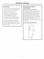
ADVANCE PLANNING
CLEARANCES
MODELS WITH A CUSTOM
• You should be able to fully open the compactor
drawer. Six inches (15.2 cm)is required on the
right side of the compactor for bag removal.
DRAWER PANEL
• Allow 23 inches (58.4 cm) in front of the
compactor to remove the drawer.
The custom drawer panel and custom handle of
your choice should be secured to the compactor
before installation begins. A template with
instructions and installation hardware is provided
with those models. For planning purposes, you
may order the template in advance by calling
1.800.GE.CARES (1.800.423.2737) or by visiting our
website at GEAppliances.com in the United States.
In Canada, call 1.800.561.3344 or visit
www.GEAppliances.ca. Order Pub. No. 31-30597.
Complete panel installation instructions are included
on the template.
Models
• This compactor is designed as a built-in
appliance only. It may be located in any
convenient space under a countertop.
DO NOT OPERATE FREE-STANDING.
• The compactor may be installed beneath
countertops of stone or other materials that will
not accept screws. No trim kit is required.
The compactor must be securely installed in a
cabinet that is firmly attached to the house
structure. Weight on the compactor drawer could
cause the compactor to tip and result in injury.
Never allow anyone to climb, sit or hang on the
compactor drawer.
ZCGP150
II and GCG1700
II
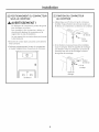
CUSTOM PANEL SIZE REQUIREMENTS:
Maximum
panel weight is 12 LBS (5.4 kg).
(1.gcm)
3/4"
Thick
Custom
Panel
_
4
2g-5/16"
(74.5cm)
14-7/8"
(37.8 cm)
Installation Preparation
ELECTRICAL REQUIREMENTS
GROUNDING REQUIREMENTS (CONT.)
WARNING!
Grounding
FOR PERSONAL SAFETY: Remove house
For your personal safety, this appliance must
be grounded while in use to reduce the risk of
electric shock. The appliance is equipped with
a three-conductor power supply cord and a
three-prong grounding-type plug to fit the proper
grounding-type receptacle. The green (or green and
yellow-colored) conductor in the cord is the grounding
wire. Never connect the green (or green and yellow)
wire to a live terminal.
fuse or open circuit breaker before
beginning installation. Do not use an
extension cord or adapter plug with
this appliance.
• The power supply cord and plug should be
brought to a separate 15- or 20-ampere branch
circuit single grounded receptacle. The outlet
box should be located within reach of the 36"
(91.4 cm) power cord.
• This appliance must be supplied with 120V,
60Hz and connected to an individual properly
grounded branch circuit, protected by a 15- or
20-ampere circuit breaker or time-delay fuse.
• If the electrical supply does not meet the above
requirements, call a licensed electrician before
proceeding.
IMPORTANT: Observe all governing
ordinances.
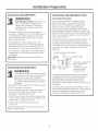
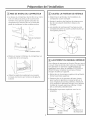
GROUNDING
codes and
REQUIREMENTS
Instructions:
This appliance is for use on a nominal 120-volt circuit
and has a grounding attachment plug as shown
in the figure below. Make sure that the appliance is
connected to an outlet having the same configuration
as the plug. No adapter should be used with this
appliance.
3-pr0nggr0unding-typewall receptacle
3 prong
gi0und,ng
Power.
supply _
cora
tt
%_
F-_------_"71,
_Gr0unded
I
'/
II
\
ilI
-_-_-,___
Grounding
---_
plug
¢op,es
ofthestandards
I,sted
may be obtainedfrom:
* National Fire
ProtectionAssociation
Batterymarch Park,
Quincy,
The improper connection of the equipmentgrounding conductor can result in a risk of
electric shock. Check with a qualified
electrician or service representative if you
are in doubt that the appliance is properly
grounded.
• Electrical Ground is REQUIRED on this compactor.
WARNING!
• DO NOT ground to a gas pipe.
• DO NOT change the power supply cord plug. If it
does not fit the outlet, have a proper outlet
installed by a qualified electrician.
• DO NOT have a fuse in the neutral or grounding
circuit. A fuse in the neutral or grounding circuit
could result in an electrical shock.
• DO NOT use an extension cord with this
compactor.
Failure to follow these instructions could result in
death or serious injury.
outlet
HA 02260
To minimize possible shock hazard, the cord must
be plugged into the proper mating three-prong
grounding-type wall receptacle, grounded in
accordance with the National Electrical Code
ANSI/NFPA70-1atest edition* and all local codes and
ordinances.
If a mating wall receptacle is not available, it is the
personal responsibility and obligation of the customer
to have a properly grounded three-prong wall
receptacle installed by a qualified electrician.
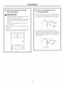
Installation Preparation
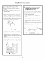
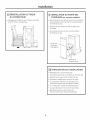
_-] UNPACKING THE COMPACTOR
• Move the compactor
location.
[_]REPLACING THE DOOR TOEKICK
{OptionalforZCGS150SS and
ZCGP15011 Models Onlg}
close to the installation
• Use a section of the shipping carton to protect
the finished floor.
ZCGS150SS and ZCGP15011 Models are supplied
with extra toekicks that can replace the toekicks
assembled on the compactor.
• Do not use the handle to lift the compactor.
• Remove all protective packaging materials such
as tape or shipping pads. Remove waxg residue
caused by shipping material with a mild solution
of liquid household cleaner and water.
• Check that the power supply cord is attached
the cord clip on the rear of the compactor.
• Lag the drawer on its side.
Remove 2 foot pedal screws. Lift off the foot
pedal.
Remove 2 door toekick screws. Remove door
toekick.
to
Install the new door toekick using the original
screws.
Cordclip
Reinstall the foot pedal using the original screws.
See Step 5 for instructions
toekick and base toekick.
_
screw
....
i_...............................
........
/
_/
T0ekick
IMPORTANT: Use the shipping carton as a pad.
Do not slide the compactor across a finished floor.
Damage will occur.
Footpedal
• Open the compactor drawer and remove any
shipping materials or other items shipped in the
drawer.
• Do not remove the compactor
II
T0ekick-_
on replacing the top
bag (if installed).
• Grasp the sides of the drawer and lift it out of the
compactor. Place the drawer on u protected
surface. The drawer can scratch a finished floor.
6
T0ekick
screw
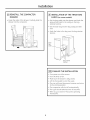
Installation Preparation
i-_ LEVELING THE COMPACTOR
@ ADJUST THE RETAINING BRACKET
• The top of the compactor should be at least 1/8"
(3 mm) from the top of the cabinet opening. You
can adjust the height of the compactor bg turning
the screws on the front leveling legs and rear
wheels.
• Determine installation depth of the compactor
beneath the countertop.
• Adjust the position of the retaining brackets so
that the screws can meet the underside of the
countertop.
Mounting clips are provided for stone or other
hard countertops that will not accept screws.
Retaining
bracket
Frontlevelinglegs
C0untert0p
Rearwheels
• Place a level inside the compactor
of the cabinet.
on the floor
r_ ADJUSTING THE BASE TOEKICK
\
• Use the leveling legs to adjust level front to back
and side to side.
A toekick extension is supplied. It can be used to
cover any gaps from the bottom of the compactor
to the floor. ZCGS150SS and ZCGP15011 Models are
also supplied with extra toekicks which can replace
the original toekicks assembled on the compactor.
• Remove the top toekick screws as shown. Lift off
top toekick piece.
Loosen the base toekick screws, adjust to touch
the floor and tighten the screws. If replacing the
toekick, remove the screws and lift off the toekick.
Install the new toekick with the original screws.
• Reinstall the top toekick piece with the original
screws.
/
Topt0ekick
Baset0ekick
Loosenscrew
on eachside
installation
POSiTiON COMPACTOR UNDER
THE COUNTERTOP
,WARNING!
When moving the compactor, use gloves to
protect and cushion your hands.
To protect the finished flooring, use a dolly to
move the compactor near the installation
location.
Failure to follow these instructions could
result in injury.
• Plug the power cord into a properly
receptacle.
grounded
• Carefully lift the front of the compactor slightly
and roll the unit into the cabinet opening.
[-_ ATTACH THE COMPACTOR TO
THE COUNTERTOP
• Use two #8-18 x 1/2" (1.3 cm) mounting screws
to fasten each retaining bracket at the top of the
compactor to the underside of the countertop.
----................_iii_;iiiiiiiii
etaining
_
_
bracket
_"-"
Mounting
screws
• If the brackets cannot be attached
to the
underside of the countertop, attach mounting
clips to the bracket. Fasten the compactor to the
cabinet front with mounting screws through the
mounting clips.
J
J
taining
..........bracket
Mounting
screw
Mountingclip
Lift here
installation
_] REINSTALL THE COMPACTOR
DRAWER
r_ INSTALLATION OF THE TRASH BAG
CADDY Ion some models}
• Grasp the sides of the drawer. Carefully slide the
drawer into the compactor.
• Set the bag caddy into the drawer and hook the
prepunched holes in the caddy on the bag
retainer buttons.
• Set the trash bag into the bag caddy and fold
over.
Hook the holes in the bag over the bag retainer
buttons.
L
bag
Trash
caddy_::__
Bag retainer
buttons
FINALIZE THE INSTALLATION
• Turn power on at the source.
Turn the knob to ON.
• Make sure the drawer is fully closed.
Lift the foot pedal to start the cycle.
The ram will travel downward,
to the starting position.
The compactor
reverse and return
will shut off automatically.
The cycle should take less than 30 seconds.
Refer to your Owner's
instructions.
Manual for operating
Notes
10
Notes
11
NOTE: While performing installations described in this book,
safety glasses or goggles should be worn.
NOTE: Product improvement
is a continuing
endeavor at
General Electric. Therefore, materials,
appearance
and
specifications
are subject to change without notice.
GE Consumer & Industrial
Appliances
General Electric Company
Louisville, KV40225
GEAppliances.com
206C!559P!96
Pub. No. 31-30256
06-09 JR
Printed in China
I
Instr
d'installation
Pour toute question, composez le 1.800.423.2737
{1.800.GE.CARES) ou visitez notre site Web _ I'adresse
GEAppliances.com
au× Etats-Unis. Au Canada, composez le 1.800.561.3344
ou visitez notre site Web
I'adresse www.electromenagersge.ca)
Compacteur
int_gr_
de 38 cm (15 po)
GCG1580 SS
GCG1500 BB
GCG1500 WW
GCG1700 II*
ZCGS150 SS
ZCGP150 II*
*Pour ZCGP150 II et GCG1700 II,
reportez-vous (]ussi (]ux
instructions sur le gabarit
fourni avec I'appareil.
Information
sur la s curit
AVANT DE
COMMENCER
Lisez attentivement
instructions.
•
IMPORTANT-
et avec soin ces
Ne laissez pas d'objets tomber ou s'accumuler
derri@e le compacteur. Le non-respect de ces
instructions pourrait provoquer un incendie.
Conservez ces instructions
pour l'inspecteur
local.
• IM PORTANT-
AVERTISSEMENT !
Respectez touslescodes
et lesordonnances en vigueur.
• Note _ l'installateur
- Assurez-vousde laisser
ces instructions
au client.
• Note au client- Gardez ces instructions
avec
votre manuel d'utilisation 6 titre de r#f#rence.
• Comp@tences requises - L'installation de cet
appareil exige des comp#tences de base en
m#canique et en #lectricit#.
• Dure_ de I'installation
- 1 heure.
• La qualit6 de I'installation
de I'installateur.
MISE EN GARDE :
Pour votre s#curit#, retirez le fusible de
la maison ou ouvrez le disjoncteur avant
I'installation, pour #viter des blessures graves ou
m_me le d@c@spouvant @tre caus6 par un choc
61ectrique.
Portez des lunettes de s#curit# pendant
I'ex#cution des travaux d'installation d#crits
dans le pr6sent manuel.
est la responsabilit6
• Toute d6faillance du produit 6 cause d'une
installation inad6quate n'est pas couverte par
la garantie. Consultez le manuel d'utilisation
pour I'information sur la garantie.
IMPORTANT
• Ce compacteur ne dolt#treutilis6
qu'6 des fins
domestiques seulement.
Utilisez
ce compacteur seulement aux finspr@vues.
Ce compacteur estcongu SEULEMENT pour des
installations
ENCASTREES.
CONTENU
Conception
IVlod_les disponibles ..............................................................
3
Dimensions et d6gagements du produit ....................3
Outils n#cessaires ................................................................
3
Pi#ces fournies ......................................................................
3
Preparation de I'installation
Exigences #lectriques
............................................................
5
Exigences de mise 6 la terre ..................................................
5
D#ballage du compacteur ......................................................
6
Mise de niveau du compacteur ............................................
7
Ajustement de la fixation de retenue ................................
7
Ajustement du panneau inf@ieur ........................................
7
Planification
pr_alable
Instructions
D@gagements ..........................................................................
4
Mod@les 6 panneau de tiroir personnalis# ................4
Positionnement du compacteur sous le comptoir ......8
Fixation du compacteur au comptoir ..............................
8
R6installation du tiroir du compacteur
............................
9
Installation du porte-sac d'ordures ....................................
9
Finalisation de I'installation
..................................................
9
d'installation
Conception
MODI_LES DISPONIBLES
GCG1580 SS
*Pour les mod61es ZCGP150 II et GCG1700
GCG1500 BB
II, reportez-vous
le gobarit fourni
GCG1500 WW
oussi au× instructions
avec ces appareils.
sur
GCG1700 I1"
ZCGS150 SS
ZCGP150 I1"
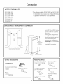
DIMENSIONS
ET DI_GAGEMENTS DU PRODUIT
• Pr6vogez un d6gagement
de 58,4 cm (2:3 po) 6 I'avant
pour I'ouverture complete
du tiroir.
j
38,1 cm
• Pr6vogez un d_gugement
de 15,2 cm (6 po) du c6t6
droitjusqu'uu
mur vertical
ou 6 I'urmoire lu plus
proche pour retirer le sac.
Remarque : ce compucteur
est conqu pour une
installation encustr6e.
min.
. .
(15 po)
86,4_ 88,9cm
(34_ 35 po)
85,8cm
(33 3/4 po)min.
88,9cm
(35 po)max.
Placezla prise_ 45,7cm (18po)
ou plusdu sol et _ 7,6 cm (3 po)
ou plus d'un c6t_ ou de I'autre.
58,4cm (23po)
37,8 cm(147/8 po)
PII_CESFOURNIES
OUTILS NFtCESSAIRES
• Niveau
,Gants
• 6 vis de montage n 8-18,
1/2 po (1,3 cm) de long
• Pmnnemu inf6rieur
• 2 fixations
• Pannemu sup_rieur
o
de Im porte
• Tournevis _] t_te Phillips
• Rubon (_ mesurer
de retenue
pour le comptoir
• Pinces
• Ponneau inf6rieur
de bose
• 2 agrmfes de montage
de c6t6
Planification
pr4alable
DI_GAGEMENTS
HODI_LES AVEC UN PANNEAU
• Vous devriez pouvoir ouvrir enti_rement le tiroir
du compucteur. II fuut 15,2 cm (6 pouces) du c6t6
droit du compucteur pour retirer le sac.
DE TIROIR PERSONNALISI_
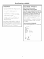
ModUles
ZCGP150
II et GCG1700
II
Le punneuu de tiroir et lu poign_e personnulise6 de
votre choix devroient 6tre fix6s au compocteur ovont
le d6but de I'instullution. Un guburit avec instructions
et quincoillerie est fourni ovec ces mod61es. Vous
pouvez commander le gabarit 5 I'avance aux fins
de planification en composant le 1.800.425.2737
(1.800.GE.CARES) ou en visitant notre site Web _]
I'adresse GEAppliances.com aux Etats-Unis. Au
Canada, composez le 1.800.561.3344 ou visitez notre
site Web a I'adresse www.electromenagersge.ca.
Commandez N° de pub. 31-30597. Des instructions
d'installation complete du panneau sont incluses
sur le gabarit.
• Pr@ogez 58,4 cm (2:3 pouces) devunt
le compucteur pour retirer le tiroir.
• Ce compucteur est conqu pour _tre encastr6
seulement. On peut le placer duns tout espuce
pratique sous un comptoir. NE L'UTILISEZ PAS
COMIVlE IvIOD_LE AIvIOVIBLE.
• Le compacteur peut _tre install6 sous les
comptoirs de pierre ou autres mat6riaux qui
n'acceptent pas les vis. Aucune trousse de
garniture n@cessaire.
Le compacteur doit @tre install6 de mani_re sore
dans une armoire solidement fix6e 5 la structure
de la maison. Un poids sur le tiroir du compacteur
pourrait faire basculer le compacteur et causer des
blessures. Ne laissez personne grimper, s'asseoir ou
se tenir debout sur le tiroir du compacteur.
TAILLE DU PANNEAU PERSONNALISI_ :
Le poids maximum
du panneau est de 5,4 kg (12 Ib).
--[
Panneau
3ersonnalis6
d'une
@aisseur
de 1,9cm
(3/4 p0)
_37,8
74,5 cm
(29 5/16 p0)
cm
(14 7/8 po)
4
Preparation de l'installation
EXIGENCES I_LECTRIQUES
EXIGENCES DE MISE _, LA TERRE {suite)
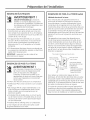
AVERTISSEMENT !
M_thode de raise 6 la terre :
SI_CURITI_PERSONNELLE : retirez les
Pour votre s6curit6, cet appareil doit _tre mis 6
la terre afin de r6duire au minimum les risques de
chocs 61ectriques. Le cordon d'alimentation b trois
conducteurs de cet appareil est muni d'une fiche b
trois broches (mise b la terre) qui se branche dans une
prise de courant murale correctement mise b la terre.
Le conducteur vert (ou verre et jaune) du cordon
d'alimentation est le fil de mise b la terre. Ne branchez
fusibles ou ouvrez le disjoncteur avant
de commencer I'installation. N'utilisez pas
de rallonge ou de fiche d'adaptation avec
cet appareil 61ectrom6nager.
• Le cordon d'alimentation
et la fiche doivent @re
branch6s dans une prise simple avec mise 6 la
terre simple d'une capacit6 de 15 ou 20 amp@es.
La boTte de sortie devrait se trouver 6 port6e d'un
cordon de 91,4 cm (:36 po).
Cet appareil doit _tre aliment6 par un courant
de 120 V, 60 Hz et branch6 6 un circuit exclusif
mis 6 la terre correctement et prot6g6 par un
disjoncteur de 15 ou 20 amp@es ou un fusible
temporis6.
Si I'alimentation 61ectrique fournie ne r6pond pas
aux exigences pr6c6dentes, appelez un 61ectricien
agr6_ avant de poursuivre.
IMPORTANT : respectez tous les codes et les
ordonnances en vigueur.
EXIGENCES DE MISE A LA TERRE
jamais le fil vert (ou vert etjaune) b une borne sous
tension.
Cet appareil est conqu pour _tre aliment6 par un
circuit d'une tension nominale de 120 volts, et son
cordon d'alimentation est muni d'une fiche de mise
a la terre, comme illustr6 dans la figure ci-dessous.
Assurez-vous de brancher la fiche de I'appareil dans
une prise de courant agant la m_me configuration
que la fiche. II ne fautjamais utiliser d'adaptateur pour
brancher cet appareil.
Prisemurale8 3 brochesavecmise 8 la terre
Fiche8 3 broches
_'"_--"'n
avec mise _ la terre
I (/-'_.._/
_'_
Cordon
d ahmentatlo
AVERTISSEMENT !
NE changez PAS le cordon d'alimentation. Si la
fiche n'entre pas compl@tement dans la prise,
faites installer une prise appropri6e par un
61ectricien qualifi6.
N'installez PAS de fusible dans un circuit neutre
ou de mise 6 la terre. Un fusible dans un circuit
neutre ou de mise 6 la terre pourrait provoquer
un choc @lectrique.
N'utilisez PAS de rallonge avec ce compacteur.
Le non-respect de ces instructions
de graves blessures ou la mort.
peut causer
mise _ la terre
_
/
/,'/_' I k_,_
o
Une mauvaise connexion du conducteur
de mise 6 la terre de I'appareil pourrait
cr6er un risque de choc 61ectrique.
Consultez un _lectricien qualifi6 ou un
repr6sentant du service si vous n'_tes pas
certain que I'appareil est correctement
mis 6 la terre.
• II FAUT une mise 6 la terre pour ce compacteur.
• N'effectuez PAS la mise 6 la terre 6 une conduite
6 gaz.
/-//Prise de courant
//]
_ la'terre
Vouspouvezobtenir
il
des copies des normes
indlquees de.
* National Fire
Battergmarch Park,
Protection Association
Ouincg, MA 02260
Pour r6duire au minimum les risques de chocs
61ectriques, la fiche doit 6tre branch6e dans une prise
de courant murale 6 trois alv6oles mise 6 la terre en
conformit6 avec la version la plus r6cente de la norme
ANSI/NFPA 70 du National Electrical Code et avec tous
les codes et ordonnances Iocaux en vigueur.
Si la prise de courant murale n'est pas appropri6e, il
incombe au client de la faire remplacer par une prise
de courant murale 6 trois alv6oles ad6quatement
mise 6 la terre et install6e par un 61ectricien qualifi6.
Preparation de l'installation
[_] DI_BALLAGE DU COMPACTEUR
• Amenez le compacteur
de I'installation.
[_] REMPLACEMENT DU PANNEAU
INFI_RIEUR DE PORTE {facultatif
pros de I'emplacement
pour les modules ZCGSISOSS et
ZCGPI5011 seulement}
• Utilisez une section de la boTte d'exp_dition
pour prot6ger le fini du plancher.
Un panneau inf_rieur suppl6mentaire
est fourni
avec les modules ZCGS150SS et ZCGP15011 pour
remplacer celui actuellement install6 sur I'appareil.
• N'utilisez pas la poign_e pour soulever
le compacteur.
• Retirez tout mat6riau d'emballage de protection
comme le ruban ou les coussins. Retirez le r6sidu
• Couchez le tiroir sur le c6t&
• Enlevez les deux vis de la p@dale. Retirez
la p@dale.
de cire du mat6riau d'exp6dition avec une solution
de d@tergent liquide doux et d'eau.
• Enlevez les deux vis du panneau inf6rieur de
porte. Retirez le panneau inf_rieur de porte.
• V6rifiez que le cordon est fix6 (_ la bride du cordon
(_ I'arri_re du compacteur.
• Installez le nouveau panneau inf6rieur de porte
en utilisant les vis enlev6es pr6c_demment.
Bride de cordon
• R6installez la p6dale en utilisant les vis enlev6es
pr6c_demment.
Pour connaTtre les directives pour remplacer le
panneau sup6rieur et le panneau inf6rieur de base,
reportez-vous (_ 1'6tape 5.
/
Vis du panneau
inferieur-_-_
|
_L
IMPORTANT : utilisez la boTte d'exp6dition comme
coussin. Ne glissez pas le compacteur sur un
plancher fini. Cela causera des dommages.
Panneau
inferieur
• Ouvrez le tiroir du compacteur et retirez tout
mat6riau d'exp_dition et autres articles exp_di6s
dans le tiroir.
• Ne retirez pas le sac du compacteur
P@dale
(s'il g a lieu).
• Agrippez les c6t6s du tiroir et sortez-le du
compacteur. Placez le tiroir sur une surface
prot6g_e. Le tiroir pourrait 6gratigner un
plancher fini.
,i' <i
i.....
Vis du panneau
inf@rieur
:,,!'i::!,_
6
Preparation de l'installation
[-_ MISE DE NIVEAU DU COMPACTEUR
• Le dessus du compacteur devrait _tre 6 au moins
0,31 cm (1/8 po) du dessus de I'ouverture de
I'armoire. Vous pouvez ajuster la hauteur du
compacteur en tournant les vis 6 I'avant des
pieds de nivellement et des roulettes arri@e.
@ AJUSTEZ LA FIXATION DE RETENUE
D6terminez la profondeur de I'installation
compacteur sous le comptoir.
du
Ajustez la position des fixations de retenue pour
que les vis puissent atteindre le dessous du
comptoir.
Les agrafes de montage sont fournies pour les
comptoirs de pierre ou autres surfaces dures qui
n'acceptent pas les vis.
Fixation
de retenue
Pieds de nivellement
avant
C0mpt0ir
_arriere
• Placez un niveau 6 I'int@ieur du compacteur
le plancher de la carrosserie.
\
1
• Utilisez les pieds de nivellement pour ajuster
le niveau de I'avant vers I'arri@e et de gauche
6 droite.
sur
r_ AJUSTEMENT DU PANNEAU INFI_RIEUR
Une rallonge de panneau est fournie. Elle peut servir
6 couvrir tous les 6carts entre le bas du compacteur
et le plancher. Un panneau suppl6mentaire est
6galement fourni avec les modules ZCGS150SS et
ZCGP15011 pour remplacer le panneau inf@ieur
d'origine install6 sur I'appareil.
• Retirez les vis du panneau sup@ieur tel qu'illustr6.
Sortez le panneau sup@ieur.
Desserrez les vis du panneau de base, ajustez
pour toucher le plancher et resserrez les vis. Si
vous remplacez le panneau inf6rieur, enlevez les
vis et soulevez le panneau inf@ieur pour I'enlever.
Installez le nouveau panneau inf@ieur 6 I'aide
des vis enlev6es pr6c#demment.
R6installez le panneau
originales.
sup@ieur avec les vis
t
Panneau/_
sup_!rieur
J
Panneau inf_!rieur
de base
Desserrez la vis
de chaque c6t_!
installation
r-6] POSITIONNEMENT DU COMPACTEUR
SOUS LE COMPTOIR
AVERTISSEMENT !
En d_plaqant le compacteur,
pour prot6ger vos mains.
portez des gants
FIXATION DU COMPACTEUR
AU COMPTOIR
Utilisez deux vis n°8-18 x 1/2 po (1,3 cm) pour
installer chaque fixation de retenue situ6es sur
le dessus du compacteur au dessous du comptoir.
Pour prot6ger le fini du plancher, utilisez un
chariot pour d6placer le compacteur et le
rapprocher du site d'installation.
Le non-respect de ces instructions
_] des blessures.
Fixation
de retenue
peut mener
_--'_
montage
• Branchez le cordon dans une prise correctement
mise (_ la terre.
Soulevez soigneusement
I'avant du compacteur
et roulez I'appareil dans I'ouverture de I'armoire.
[]
• Si les fixations ne peuvent pas #tre installe6s
sous le comptoir, fixez les agrafes de montage
(_ la fixation. Fixez le compacteur (_ I'avant de
I'armoire avec les vis de montage (_travers
les agrafes de montage.
i
ation
de retenue
_'_--_
Agrafe de
montage
Soulevez ici
Vis de
Vis de
montage
installation
_] RI_INSTALLATION DU TIROIR
DU COMPACTEUR
[_] INSTALLATION
• Agrippez les c6t6s du tiroir. Glissez avec soin
le tiroir dans le compacteur.
• Placez le porte-sac dans le tiroir et accrochez les
trous pr6perc6s dans le chariot sur les boutons
de retenue du sac.
D'ORDURES
DU PORTE-SAC
(sur certains modules}
D6posez le sac d'ordures
et repliez.
dans le porte-sac
Accrochez les trous du sac sur les boutons
de retenue du sac.
(
Porte-sac
d'ordures
m6nag_res
B0ut0ns de
retenue du sac
_0] FINALISATION
DE L'INSTALLATION
• R_tablissez le courant
61ectrique.
• Tournez le bouton de commande
Assurez-vous
a ON (Marche).
que le tiroir est bien ferm6.
Soulevez la p6dale pour amorcer le cgcle.
Le coulisseau effectue une descente, puis
remonte et retourne a sa position initiale.
Le compacteur
s'6teint automatiquement.
Le cycle doit durer moins de 30 secondes.
Reportez-vous aux instructions de
fonctionnement
du manuel d'utilisation.
Notes
10
Notes
11
REMARQUE : en ex6cutant les installations d6crites dans
ce manuel, portez des lunettes de s6curit6.
REHARQUE : General Electric cherche continuellement 6
am61iorer ses produits. Par cons6quent, les mat@iaux
I'apparence et les sp6cifications peuvent @re modifi6s sans
pr6avis.
GE Consumer & Industrial
Appliances
General ElectricCompany
Louisville, KY40225
GEApptiances.com
Pub. No. 31-30256
206C1559P196
06-09
JR
Imprim6 en Chine