1
SF_AIRS
Kenmore
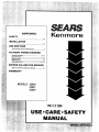
CONTENTS
SAFETY
........... , .............. . .............................
............... .....1-3
INSTALLATION
.........................,..............,.............. ...................
4-7
USE
AND
CARE
Your Counter Unit and Its Features ..........................
TO START
THINGS
8
COOKING
Cooktop Cooking ....................................................
8. g
Control Knobs .............................................................
9
Spark Ignition ..............................................................
9
Cleaning Tips ............................................................
10
Removsble Parts .................................................
11-12
BEFORE
CALLING
FOR SERVICE
What to 0o Before Calling for Service .................... 12
WARRANTY
MODELS
32O2O
32O21
32025
MAR2 9z00e
USE • CARE • SAFETY
MANUAL
IMPORTANT
INSTRUCTIONS
FOR
YOUR
SAVE
Read
appliances,
all instructions
basic
safety
before
SAFETY
THESE
using
precautions
I
WARNING:
INSTRUCTIONS
this appliance.
should
be followed,
When
using
including
electrical
the
following:
I
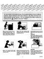
If the InformaUon In this manual Is
not followed exactly, a fire or explosion may result
causing property damage, personal Injuryordeath.
-- Do not store or use gasoline or other
flammable vapors and liquids In the vicinity
of this or any other appliance.
-- WHAT TO DO IF YOU SMELL GAS
Teach children not to play with control
knobs or any other pert of the counter unit.
• Do not try to light any appliance!
Never leave children alone or unattended
where a counter unit Is In use.
• Do not touch any electrical switch; Do not
use any phone In your building!
• Immediately call your gas supplier from a
nelg hbor's phone. Followthe gas suppller's
Instructlonsl
• If you cannot reach your gas supplier, call
the fire department.
-- Installation and service must be performed
by a qualified Installer, servlca agency orthe
gas supplier.
L. P. BURNER
Never let anyone climb, sit or stand on an
open oven door or any part of the counter
unit.
ADJUSTMENTS
The adjustments In the Installation Section must
be made before you try to use the counter unit.
If you are using Liquefied
Petroleum
Gas
(bottled gas) all L.P. adjustments In the Installation
Section must be made before use.
If your oven Is not properly adjusted, the flames
may be too high, or the unit may use too much fuel,
release toxic fumes or cook poorly.
Never leave cookfop elements/burners
unwatched at high hest settlngso Bollovers
cause am oklng and greasy splllovers could
catch fire.
NGSAF1
Never use your counter unit for
warming or heating a room. You
could be burned or seriously Injured. Such mlsuse could also
cause damage to the counter unit.
Never wear loose clothing when
using your counter unit. Such clothIng could catch fire.
Always keep the counter unit area
clear and free from things that will
burn.
CAUTION:
Never store things In an ovenor
near cooktop elements/burners.
These things may catch fire and
plastic Items could melt.
CAUTION:
Never use a towel or other bulky
cloth as a potholder. Such cloths
could catch fire.
Never let pot handles stick out over
the front of the counter unit, Turn
handles in so that they cannot be
bumped Into, Keep the handlesaway
from other hot surface elements/
burners.
2
Do Not store Items of Interest to
children above a counter unit.
Children climbing on a counter unit
to reach such Items could be serlously injured.
NGSAF09
IMPORTANT
SAFETY
INSTRUCTIONS
Keep this book for later use.
Never try to move a pan of hot fat, especially a deep fat
fryer. Watt until the fat has cooled.
Be sure your counter untt Is Installed and grounded
properly by a qualified technician.
Always keep the counter unit area clear and free from
things that will burn, gasoline and other flammable
vapors and liquids.
Never try to remove burner bowls from glass top ranges.
Never operate the burners unless the burner tops are In
place.
Always keep the counter unit clean by following Instructions In this book. Food and grease are easy to
Ignite. Clean the counter unit and vent hoed regularly.
Only some kinds of glass or ceramic pans can be used
for cooktop cooking. Be sure that the pan you use will
not break when heated on the cooktop burners.
Always keep combustible wall coverings, curtains or
drapes, wooden utensils, plastic utensils or canned
food a safe distance away from your counter unit.
Always use dry potholders when removing pans from
the cooktop.
Molat or damp potholders can cause
steam burns.
Always
follow cleaning Inatructlons
Never clean cooktop surface when It Is hot. Some
cleaners produce noxious fumes and wet cloths could
cause steam burns If used on a hot surface.
In this book.
Never try to repalr or raplace any part of the counter unit
unless Instructions are given In this book. All other
work should be done by a qualified technician.
Always use care when touching the cooktop.
The
glass surface ot the cooktop will retain heat after controls have been turned off.
Never heat unopened food containers. Prassure buildup
may make container burst and cause Injury.
Never leave jars or cans of fat or drippings on or near
the counter unit. Never let grease build up on your
counter unit. You can keep grease fires from starting If
you clean up grease and spills after each oven use.
Always keep dish towels, dish cloths, potholdera and
other linens a safe distance away from your counter
unit. Never store such Items on your counter unit.
Do not use a wok on the cooking surface If the wok has
a round metal ring which is placed over the burner grate
to support the wok. This ring acts as a heat trap which
may damage the burner grate and burner head. Also, It
may cause the burner to work Improperly. This may
cause a carbon monoxide level above that allowed by
current standards, resulting In a health hazard. Exposure to carbon monoxide may cause birth defects or
other reproductive harm according to the California
safe Drinking Water and Toxic Enforcement Act.
Never use aluminum foil to line drip bowls. Improper
use of foil could start a fire and cause Incomplete
combustion.
Never block the flow of combustion and ventilation air
through cooktop burners.
COOKTOP
Be sure everyone in your home knows what to
do in case of fire!!
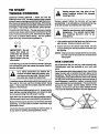
Never pick up a flaming pan...Instead:
1. Turn off the burner.
Read and understand this information NOW!
Should you ever need it, you will not have time
for reading.
2. Smother the fire with a tighUy fitting pan lid,
baking soda or with a dry chemical or foam
type extinguisher.
Never use water on a grease fire -- it will only
spread the flames.
IMPORTANT
SAFETY
GREASEFIRE
NOTICE
The California Safe Drinking Water and Toxic Enforcement Act requires the Governor of California to publish
a list of substances known to the state to cause cancer,
birth defects, or other reproductive harm and requires
businesses to warn customers of potential exposure to
such substances. Gas appliances can cause minor
exposure to four of these substances, namely benzene,
carbon monoxide, formaldehyde and soot, caused primarily by the Incomplete combustion of natural gas or
L.P. fuels. Properly adjusted ranges, Indicated by a
bluish rather than a yellow flame, will minimize Incomplete combustion. Exposure to these substances can be
minimized further by venting with an open window or
using a venUlatlon fan or hoed.
3
NGSAF10
INSTALLATION
IMPORTANT:
with
the
TOOL
Leave
these
instructions
OWNER:
Keep
future
use.
appliance.
LIST
these
instructions
for
LOCATION
The following tools are needed to Install your new
counter unit.
Pipe wrenches
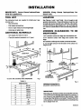
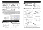
See Figures 1 and 2 and Table 1 for all rough-In and
spacing dimensions. These dimensions must be met
for safe use of your counter unit. See Fig. 3 for recommended location of gas supply line. Do not Install the
unit near an outside door or where a draft may affect Its
use.
Flat bladed screwdriver
• Rule or tape measure and straightedge
• Hand saw or saber saw
ADDITIONAL
MINIMUM
CLEARANCES
MAINTAINED:
MATERIALS
TO
BE
• Gas supply line shut-off valve
1-3/4" between cutout rear edge and wall behind unit.
•
3-1/4" between
edge.
Pipe joint sealant (resistant to L.P. gas)
cutout front edge and counter front
30" between cooktop and nearest overhead surface.
3" on the right and on the left side of the cutout to a
height of 18".
30" MIN.
TO CABINET
I
3" MIN.
CLEARANCE
18" MIN.
I"
TO SIDE WALL .TO CABINET
J
CLEARANCE
CUTOUT AND COUNTER UNIT DIMENSIONS
_
//
II
Fig. 1
TABLE 1
" '
DIMENSIONS
Fig. 2
MINIMUM CLEARANCES TO
ADJACENT CONSTRUCTION
A
30 1/4"
B
21 1/4"
C
28-3/8"
D
19-3/8"
IMPORTANT:
E
19-1/2"
F
28-1/2"
G
14-1/4"
H
3"
J
1-3/4"
Reaching over surface burners can cause fire or burns.
You should not use storage space above the cooktop. If
you choose to use cabinets above the cooktop, install
a range hood that sticks out at least 5" beyond the front
of the cabinets. Cabinets Installed above a cooktop may
benD deeperthan 13".
K
3-1/4"
4
NGINS18
PREPARATION
GAS CONNECTIONS
Adequate counterspace must be provided for the unit.
The area should be easy to reach and be lighted with
natural light during the day.
Call your gas supplier and ask which codes apply In your
area. If there are no codes, you must follow the NATIONAL FUEL GAS CODE, ANSIiZ223.LStest Edition.
You can get a copy by writing:
See t he first page for cutout dimensions. Mark the cutout
on t he counter. Use a hand or saber saw to make t he cut.
ELECTRICAL
American Gas Association
1515 Wilson Boulevard
CONNECTIONS
Arlington (Rosslyn), VA 22209
Call your Electric Company and ask which codes apply
In your area. If there are no codes, you must follow the
NATIONAL ELECTRICAL CODES, ANSI/NFPA NO. 70Latest Edition. You can get a copy by wrlUng:
Know where your main gas shut off valve Is.
Shut off gas supply before removing an old range. Leave
It off until hookup of new counter unit Is finished.
National Fire Protection Association
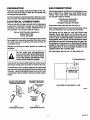
See figures on this page for rigid and flexible pipe
hookups. Some local codes do not allow the use of
copper gas pipe. If flexible connectors
are allowed,
a new A.G.A. certified
flexible connector
is rec.
omrnended.
Never reuse an old connector
when
installing a new unit. A manual shut-off valve, for
the purpose of turning on or shutting off the gas
supply to the appliance,
must be installed in the
gas supply line at anaccessible
location in the
cabinet below the counter unit.
Batterymarch Park
Quincy, MA 02269
The counter unit cord has a three prong plug and must
be plugged Into a properly grounded three hole outlet.
The outlet must be In a standard 120 Volt, 60 Hertz AC
household circuit.
Improper grounding can spark Ignition on models so
equipped.
We recommend that you use 1/2" gas supply line.
Do not under any circumstances
cut or remove the grounding
prong
from the counter unit cord. Failure
to provide proper polarization
may
cause shock and tire hazard.
1"FROM BACKWALL
If you do not have a grounded three hole outlet, have an
electrician change your old outlet or Install a new one.
.<_121/2,_,_
TO temporarily use a properly polarized and grounded
two hole outlet until a grounded three hole outlet can be
Installed, a grounding adapter plug may be used. Have
an electrician test the outlet to be sure It meets requirements.
PLUG WITH GROUND PRONG
PROPERLY POLARIZED AND
GROUNDED RECEPTACLE
_
FROMCUTOUT
CENTER
UNE
POLARIZED RECEPTACLE
PROPERLYGROUNDED
METAL EYELET
GROUND
LOCATION OF GAS SUPPLY LINE
FIG.3
RECEPTACLE
PLATE
MOUN_NG
SCREW
Fig. 1
PREFERRED METHOD
Fig. 2
TEMPORARY METHOD
5
NGINS19
GAS CONNECTIONS
Use pipe wrenches to make connections.
strain on the connection line assembly.
(continued)
A pressure regulator IS supplied and must be Installed
In the gas supply line underthe unit. Install the regulator
in the gas supply line between
the shut off valve
and the unit connection
(see Fig ure 5). The top of the
regulator should face toward the cabinet front and be
easily accessible through the cabinet doors.
Do not put any
Any openings around gas and electric outlets must be
sealed at the time of Installation. When you are finished
making connections, be sure that control knobs are
turned to OFF before you open the main gas supply
valve.
See next page for information on placing burner tops on
cooktop burners.
NOTE: The pressure regulator Is set for natural gas. To
use L.P. gas, the regulator must be converted.
To convert for L.P. gas, unscrew the cap and remove the
spring retainer (see Figure 4). Turn the spring retainer
over and put It back Into the regulator. L. P. should be
visible on the spring retainer. Replace the cap.
TO CHECK
FOR LEAKS:
Apply a soap solution to all gas connections.
will form where any gas Is leaking.
DO NOT use an open flame
Bubbles
to look for leaks.
Turn off main gas supply before you try to stop a leak.
NAT.
m
Turn main gas supply back on and recheck connections
after stopping any leaks.
L.P.
6,,w.c.....
w.c.
Be sure all leaks are stopped before lighting pilots
(some models) or burner.
I--I
_L*
I===l
PRESSURE
Fig. 4
CAUTION:
The range and its individual
shut off
valve must be disconnected
from the gas supply
piping system during any pressure testing of the
gas supply system at test pressures in excess of
1/2 psig (pounds per square inch gauge).
PRESSURE REGULATOR
,_19
112" CUTOUT-_
The range must be Isolated from the gas supply piping
system by closing Its Individual shut off valve during
any pressure testing of the gas supply system at test
pressures equal to or less than 1/2 pslg.
_:'._ 45 °
I
PRESSURE _
INFORMATION
The maximum allowable test pressure for the regulator
is 14" W.C. The minimum pressure needed to check the
regulator setting is 7" W.C. for natural gas or 11 "W.C. for
L.P. gas.
L ....
L_d
TEST
_
I
I
I
f
I
I
RECOMMENDED
PIPE HOOK-UP
Fig. 5
6
NGINS28
REMOVING
SHIPPING
SCREWS
Lift the cooktop (g rasp at front) and remove the shipping
screw from each of the four surface burner assemblies
(see Fig. 7). The screws can be discarded.
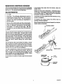
If the flames blow away from the burner, close the
shutter more.
Check the Inner cone of the flame. It should be about
11/16" long. If the length of the inner cone of the flame
Is not correct, use a 1/2" open end wrench or adjustable
joint pliers to adjust the orifice hood.
ADJUSTMENTS
L.P. GAS
CAUTION:
The following adjustments must be
made before turning on the burner. Failure to do so
could result in serious injury. Be sure pressure
regulator has been converted as described on
previous page.
To shorten the cones, fig hten the orifice hood by turning
In the L.P. direction.
To lengthen the cones, loosen the orifice hood by
turning in the Nat. direction.
Burner flames should be checked frequently and adjustments made as necessary.
Remove the control knobs and the control panel.
Use a 1/2" open end wrench to turn the orifice hood
in the L.P. direction. See Figure 8. Turn the orifice
hood about 1 1/2 turns or until snug. Do not
overtig hten or you may distort the orifice hood and
needle.
SHIPPING SCREW
The unit has been factory adjusted for use with the most
common type of natural gas. The gas used in some
parts of the country may be different. In order to assure
safe and energy efficient operation, check adjustments
described below. If you are using L.P. gas, the orifice
hoods and pressure regulator must be converted as
described above, before making any burner adjustments.
Turn all burners full on and check the flames.
Burner
flames should not flutter or blow away from the burner.
They should be blue In color with no trace of yellow.
Foreign particles in the gas line may cause an orange
flame at first, but this will soon disappear.
L.P.
ORIFICE HOOD
To make adjustments, remove the control knobs and
panel. Use pliers to adjust the air shutter. Be sure to
keep the gap In the air shutter facing straight up. Be
very careful
not to bend the air shutter
when
using pliers to make adjustments.
AIR SHU'I-rER
INNER CONE
OF FLAME
if the flames are yellow or flutter, open the air shutter
more.
11/16"
COOKTOP
BURNER
7
NGINS29
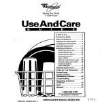
YOUR
COUNTER
UNIT
IMPORTANT:
The model and serial number of your counter unit can be found on a tag
on the underside of the unit.
COOKTOP CONTROLS
(See page 9)
BURNER GRATE
(See page 10)
(See page 11)
BURNER BOWL
(See page 10)
COOKTOP
(See page 11)
8
NGCUF02
TO START
THINGS
COOKING
During burner
glass €ooktop
could get hot.
COOKTOP SPARK IGNITION -- When you turn the
cooktop knob to LITE, the spark Igniters make a series
of electric sparks (ticking sounds) which light the burner.
After the burner Ignitesthetlcklng wlllstop. Ifthetlcklng
sound persists afterthe burner lights, turn the burner off
and rellg ht. If the ticking Is still present, call for eervlce.
During a power failure the burners will not light
automatically. In an emergency, a cooktop burner may
be lit with a match by following the steps below.
TO OPERATE CONTROLS --The sign near each cooktop
control knob shows which burner Is turned on by that
knob. Push to turn knob to LITE. After the burner lights,
turn knob to desired flame setting. All four Igniters
spark when any control knob Is pushed In.
IMPORTANT:
Do not
leave
the
knob
on
LITE after the burner
tights, or life of the
spark igniter my
be
shortened.
Lighting gas burners with a match is
dangerous.
You should match light
the cooktop
burners
only in an
emergency.
1. Light a match and hold the flame near the burner you
want to light. Wooden matches work beat.
OFF
O0
eO
use, the area of the
around
the burners
2. Push in and turn the control knob slowly. Be sure
you are turning the correct knob for the burner you
are lighting.
NOTE:
I
If the burner does not light within four seconds,
turn the knob off and walt five minutes before
trying again.
/
_
LrrE
WOK COOKING
Avoid leaving any burner on without a utensil. Doing so
can overheat the grate and cause the enamel finish to
become damaged.
We recommend that you use only a flat-bottomed wok.
Flat-bottomed woks are available at your local retail
store.
Do not use woks which have support rings. Use of these
types of woks, with or without the ring In place, can be
dangerous. Placing the ring over the burner grate may
damage the burner grate and burner head. Also, placing
the ring over the burner grate may cause the burner to
work Improperly resulting In carbon monoxide levels
above allowable current standards. This could be dangerous to your health. See the Safety Section of this
manual. Do not try to use such woks without the ring.
You could be seriously burned If the wok tipped over.
As a safety precaution you should set
controls so flame heats pan bottom only
and does not lick pan sides. Flames licking
pan sides are unsafe and waste heat.
If a cooktop burner falls to IIght within five seconds, turn
the knob to OFF and wait five minutes before trying
again. If the burner still will not light, check the service
section In this manual.
Watch food when heating quickly on HI. As soon as the
food reaches cooking temperature, turn down the heat
to the lowest setting that will keep It cooking.
High flame may be used to boll large quantities quickly. _'_
It is also used to start food cooking quickly In large pans.
Medium Flame may be used for even browning with little
spattering, it is also used to malntaln a boll with large
(('_
_,_
/_
///J/
quantities of food.
Low Flame may be used for melting or warming food. It
Is also best for cooking small quantities of food.
g
NGCUF03
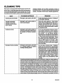
CLEANING
Referalsoto
TIPS
next page when cleaning yourcounterunlt.
Cooktop finishes will be either porcelain enamel or
brushed chrome. Porcelain enamel looks like a painted
surface. Brushed chrome has a metallic appearance.
Warm water, a mild detergent and a soft cloth are safe to
use on all cleaneble parts of your counter unit. Do not
use metal scouring pads, except where recommended.
PART
CLEANING
MATERIALS
REMARKS
Control panel and knobs
Detergent, warm water, soft cloth
Do not use abrasive cleaners.
off for easter cleaning.
Knobs pull
Porcelain enameled
cooktop, area under
cooktop, burner grates,
burner bowls
Detergent, warm water, plastic or
nylon scouring pad
Clean after each splllover. Rub chrome
bowls (some models) gently with scourIng pad. Soak stubborn soil. Bowls can
be removed during burner use to keep
clean and to avoid discoloration caused
by excessive heat.
Cooktop burners
Detergent, warm water, plastic or
nylon scouring pad or boll In DipIt® solution to remove stubborn
soll
Do not use all-purpose cleaners, ammonia, powder cleansers or oven cleaners.
Such products can scratch or discolor
the burners.
To use DIp-R® solution,
remove burners and boll for 20 minutes In
2 Tbsp. Dip-It® granules par quart of water. Boll with burner head down. Rinse
theroughly, draln and completely dry burners In a 200°F oven for 1/2 hour. After
cleaning or a splllover, light the burners
and make sure that no ports are clogged
(see next page).
Brushed chrome cooktop
Detergent, warm water, soft cloth
or a chrome cleaner or special
cooktop cleaning creme
Do not scour chrome tops. Stubborn
stains may be removed by using Espree
Magwheel Cleaner®or Turtle Wax PolishIng Compound®. To remove finger prints
on brushed chrome, apply a Ilttlebaby oll
with e paper towel. Rub In the direction of
the brush marks. Armor All Protectant®
can also be used (after cleaning). Be sure
to clean spills of acidic foods quickly.
Vinegar spills can permanently
stain
chrome.
If cleaning methods described above prove Ineffective, baked-on food residue or
stains on ch rome cooktops can he removed by usln g pad type oven cleaners. Use
extreme caution. Oven cleaners are caustic and will damage painted or aluminum
surfaces, such as range sides, backguard or control panel. Do not use spray type
oven cleaners. Overspray will damage nearby painted surfaces and heating
elements. Use several layers of newspaper and masking tape to cover surfaces
such as the backguard, control panel, range sides, countertops, etc. Apply the
pad type oven cleaner evenly to the entire top surface. The entire top must be
cleaned to keep the finish consistent In color. Use extreme caution to prevent the
oven cleaner from coming In contact with any other surface. Let the cleaner
remain on the top for 20-30 minutes. Rinse the top well to remove every trace of
oven cleaner. Dry the top and apply Armor All Protectant® to protect the finish.
lO
NGCCH04
LIFT-UP
COOKTOP
The cooktop can be raised or removed so the area
underneath (burner box bottom) can be cleaned.
To raise ¢ooktop:
1. Remove the burner grates, bowls and knobs.
2. Grasp the cooktop at the front and lift up.
3. Raise the support rod Into place to hold the cooktop
while cleaning. Securethe rodlnto the spacer bracket
on the cooktop.
Porcelain enamel can chip If dropped. Handle porcelain
enameled cooktops carefully.
To lower
the cooktop:
1. Carefully replace the support rod and lower the
cooktop. Press into place. Make sure the strikes fit
in the catches to fasten the cooktop.
2. Replace the burner grates, bowls and knobs.
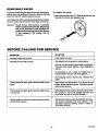
REMOVABLE
BURNERS
COOKTOP
The cooktop burners on your range may be removed for
cleaning. Be sure all cooktop knobs are turned to
OFF and burners are cool, then rentove or raise
the cooktop.
GAS VALVE
ORIFICE
If shipping screws were not removed from the burner
when the range was Installed, do so now (see your
Installation section for Instructions).
To remove
burners:
1. Grasp the burner head and tilt It to the right to release
the two tabs from the burner support (A In Fig. A).
2. Lift the end of the burner assembly, then pull away
from the front of the range to free the air shutter from
the gas valve orifice (Fig. B). Check all lighter and
burner ports. If they are clogged, use a wire or needle
to clear them.
AIR SHUTTER
See the Cleaning Chart.
MGHTER PORTS
Be careful not to disturb the air shutter setting
while cleaning.
If you need to readjust the air shutter,
see the Installation Section.
To replace
1. Sliptheair
IGNITE_
burners:
shutterover
the gas valve orifice (Fig. A).
_
2. Lower the burner assembly and hook the tab in the
slots In the burner support (Fig. A).
3. Be sure both tabs are in their slots, that the burner
sits level and straight and that the flash tube forms a
straight line from the igniter to the burner (Fig. B).
_
FLASH TUBE
BURNER PORTS
11
NGMN_5-1
REMOVABLE
KNOBS
To replace
All control knobs may be removed for easy cleaning by
pulling the knob straight off the stem. Be sure that the
knob Is In the OFF position before removal.
the knob:
1. Match the flat side of the "D" Shaft on the knob to the
flat side of the stem and replace knob.
Hint: Slip a thin cloth (such as a handkerchief) or a piece
of String under and around the knob edge and pull up.
Caution:
Read
these
instructions
carefully
before replacing the knobs. Replacing
the knobs improperly
will damage the
knobs and the spring clip on the stems.
If this happens,
the knobs will fit
loosely.
BEFORE
CALLING
FOR SERVICE
PROBLEM
SOLUTION
Cooktop knobs will not turn
Push knobs In to turn.
Cooktop burners will not light
Gas supply not connected or not turned on.
Counter unit not properly grounded or polarized.
This can affect spark Ignition. See Installation
section.
No eleCtricity to unit; check for tripped fuse or
circuit breaker. Be sure unit Is plugged In.
Soil clogging
clean.
holes In burner top.
Remove and
Ticking sound of spark Igniter persists after burner
lights
Spark Igniter not deactivated. Turn burner off and
rellght. Some ticking Is normal. If ticking Is excessive, call for service.
Ticking sound of spark Igniter persists after burner
isturned off
Soil buildup at back of knob. Be sure knob Is in the
OFF position.
Pull knob straight off stem and
check back of knob for any soil buildup.
Heavily soiled or stained chrome cooktop cannot be
satisfactorily cleaned
See the Instructions under cleaning tips, for cleanIng chrome cooktops with oven cleaner.
This
procedure requires extreme caution.
Read Instructions carefully.
12
NGCUS02
NOTES
13
KENMORE
GAS COUNTER
UNIT
WARRANTY
FULL ONE YEAR WARRANTY
ON THE FUNCTIONING
PARTS EXCEPT GLASS PARTS
Dear Customer:
Our constant
directed
efforts are
toward
making
sure your new Kenmors
Counter Unit will arrive at
your home In perfect condltlon
and will give you
proper performance.
As
part of these efforts, we
feel it Is our responsibility
to provide
you with this
warranty for your range.
OF ALL
If, within one year from the date of Installation, any part, other than a glass
paN, falls to function properly due to a defect In material or workmanship,
Sears will repair or replace It, free of charge.
FULL 30-DAY WARRANTY ON GLASS PARTS AND FINISH OF PORCELAIN ENAMEL, PAINTED OR BRIGHT METAL FINISHED PARTS
If, within 30 days from the date of installation, any glass part orthe finish on
any porcelain enamel, painted or bright metal part Is defective In material or
workmanship, Sears will replace the part, free of charge.
FULL 90-DAY
WARRANTY
ON MECHANICAL
ADJUSTMENTS
For 90 days from the date of Installation, Sears will provide, free of charge,
any mechanical adjustments necessary for proper operation of the range,
except for normal maintenance.
If the unit Is subjected to other than private family use, the above warranty
coverage Is effective for only 90 days.
WARRANTY
SERVICE IS AVAILABLE
BY CONTACTING
THE
NEAREST SEARS SERVICE CENTER/DEPARTMENT
IN THE
UNITED STATES
This warranty applies only while this product Is In use In the United States.
This warranty glvss you specific legal rights, and you may also have other
rights which vary from state to state.
SEARS, ROEBUCK and CO.
Dept. 731 CR-W
Sears Tower
60684
WE SERVICE
WHAT
WE SELL
"We Service What We Sell" Is our assurance to you that you can depend on Sears for service because Sears
service Is nationwide.
Your Kenmore Counter Unit has added value when you consider that Sears has a service unit near you staffed
by Sears trained tech nlclans.., profeselonal technicians specifically trained on Sears appliances, having the
parts, tools and equipment to ensure that we meet our pl_.dge to you -- "We Service What We Sellr'
TO FURTHER
ADD TO THE VALUE
OF YOUR
RANGE,
BUY A SEARS
MAINTENANCE
ysarsofOwnenshlpCovsrags
Kenmore Counter Units are designed, manufactured and tested for years of dependable operatlon. Yet, any modern appliance may require
service from time totlme. The Searswarrantyplus
the Sears Maintenance Agreement provides protectlon from unexpected repair bills and assures
you of enjoying maximum range efficiency.
Here's a comparative warranty and Maintenance
Agreement chart showing you the benefits of a
Sears Range Mafntenance Agreement.
1
AGREEMENT.
lstYear
2ndYear
3rdYear
MA
MA
MA
MA
W
MA
MA
MA
MA MA
Replacement
of Detective
parts
other
than
Porcelain W
or Glass
90 DAYS
2
.._.._.,A.ju_m..,
W
3
po_..,..ndG_.p._.
30 DAYS
Annual Preventlvm Malnten4
,rice Chmck ,t your rIKlUeS_
W * Warran_
14A- MJinlena_ce Agreement
CONTACT YOUR SEARS SALESPERSON OR LOCAL SEARS SERVICE
CENTER TODAY AND PURCHASE A SEARS MAINTENANCE AGREEMENT.
Id_(_ I"1 _
O I"(_
® America's
Sold by SEARS,
I
ROEBUCK
Best
Selling
AND CO., Chicago,
Appliance
Brand
IL 60684
III I II