1
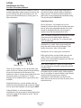
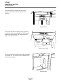
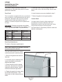
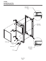
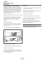
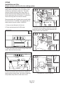
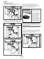
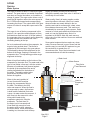
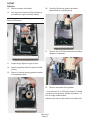
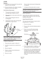
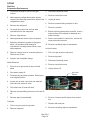
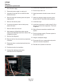
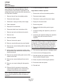
SCN60
Installation and Use
Introduction
This manual includes information for the
installation, operation and maintenance of the
SCN60 residential ice machine.
The SCN60 was developed to offer fans of
Scotsman’s Nugget Ice form the ability to have that
ice in their homes. Previously Nugget Ice was only
available in commercial establishments, where it
developed a strong following because of the
chewable nature of the ice. This machine makes
authentic Nugget ice, using the same process as
the larger commercial machines.
Table of Contents
Product Description: . . . . . . . . . . . . . . . . . . . . . . . . . . . . . . . . . . . . . . . . . . . Page 2
Cabinet Dimensions . . . . . . . . . . . . . . . . . . . . . . . . . . . . . . . . . . . . . . . . . . . Page 3
Location Recommendations: . . . . . . . . . . . . . . . . . . . . . . . . . . . . . . . . . . . . . . . Page 4
Familiarization . . . . . . . . . . . . . . . . . . . . . . . . . . . . . . . . . . . . . . . . . . . . . . Page 5
Decorating Features: . . . . . . . . . . . . . . . . . . . . . . . . . . . . . . . . . . . . . . . . . . . Page 6
Door Panel Attachment . . . . . . . . . . . . . . . . . . . . . . . . . . . . . . . . . . . . . . . . . . Page 7
Door Swing . . . . . . . . . . . . . . . . . . . . . . . . . . . . . . . . . . . . . . . . . . . . . . . . Page 8
Plumbing - Pump Model . . . . . . . . . . . . . . . . . . . . . . . . . . . . . . . . . . . . . . . . . Page 9
Plumbing: Gravity Drain Model . . . . . . . . . . . . . . . . . . . . . . . . . . . . . . . . . . . . . . Page 10
Electrical and Start Up . . . . . . . . . . . . . . . . . . . . . . . . . . . . . . . . . . . . . . . . . . Page 11
Use . . . . . . . . . . . . . . . . . . . . . . . . . . . . . . . . . . . . . . . . . . . . . . . . . . . . Page 12
Maintenance . . . . . . . . . . . . . . . . . . . . . . . . . . . . . . . . . . . . . . . . . . . . . . . Page 13
How to remove scale from the ice making system. . . . . . . . . . . . . . . . . . . . . . . . . . . . Page 14
Outdoor Use Notice:
Keep from freezing. Severe damage will occur to the unit if left in or operated in temperatures beyond
the limits listed in this manual. That damage is NOT covered by warranty.
Keep dry. Do not locate in low lying areas where puddles will accumulate.
Provide Shade: Heat gain from the sun will reduce the unit's ability to make and store ice, and
ultraviolet radiation from the sun can potentially damage the unit's plastic components.
Water Supply: Avoid a long run of hose or tubing exposed to the sun. Plastic water supply tubing
should be rated for potable water and include UV protection. Copper tubing is recommended.
Back Flow Prevention: The unit includes back flow prevention, no additional check valve is required.
Drainage: Do Not drain into swimming pool or onto grounds.
May 2011
Page 1
SCN60
Installation and Use
Product Description:
This ice machine is designed to be used indoors, in Water Quality
a controlled environment or outdoors within certain
limits.
The water to the machine must be potable, or fit for
human consumption. Beyond that, water supplies
The SCN60 is made up of two major systems: the
vary in the degree of mineral content. As this ice
ice making system and the ice storage system. The machine makes ice, all the water that flows into the
ice making system is a continuous flow type ice
machine is changed into ice. That includes any
machine, it makes ice when the ice level becomes minerals that might be in the water. However,
low and stops when it is full.
during ice making some minerals will stick to the
ice making components. The higher the mineral
The ice storage system is an insulated chest with a content, the more mineral build up will occur. Water
drain at the bottom for melting ice. It is not
filters are a partial help, as they will remove the
refrigerated, insuring that the bin contains fresh ice. suspended solids, but water treatment is needed
for the dissolved solids, which are part of the water
Installation Information
and cannot be filtered out.
Dimensions:
RO Water
The cabinet is fourteen and seven eighths inches
wide by thirty three and three eighths to thirty four
and three eighths inches high.
This machine can be supplied with Reverse
Osmosis water, but the water conductivity must be
no less than 10 microSiemens/cm. A reverse
osmosis system should include post treatment or
blending to satisfy the R.O. water’s potential
aggressiveness.
Utility and Operational Requirements
• The SCN60 must be connected to a potable
•
•
•
•
•
water supply.
The water supply must have a conductivity of
at least 10 microSiemens/cm.
Minimum water pressure: 20 psi
Maximum water pressure: 80 psi
Minimum water temperature: 40 degrees F.
Maximum water temperature: 90 degrees F.
It is designed to operate in wide range of air
temperatures:
• Minimum air temperature: 50 degrees F.
• Maximum air temperature: 100 degrees F.
Although the machine will function within the listed
ranges, it works best at water temperatures
between 50 and 60 and air temperatures between
60 and 80.
Note: Ice making capacity goes down as the
environmental temperatures go up, and will be
severely reduced at temperatures over 90 oF.
Deionized water is not recommended and could
damage the machine.
Because water softeners exchange one mineral for
another, softened water may not improve water
conditions when used with ice machines
Electrical power
The unit must be on its own 115 volt, 60 Hz, 15
amp circuit. It is equipped with a power cord and
can be plugged into a nearby outlet. Extension
cords are not allowed by most codes. Follow all
applicable codes.
Warranty Information
Warranty information is supplied separately from
this manual. Refer to it for coverage. In general, the
warranty covers defects in materials or
workmanship and does not cover corrections of
installation errors or maintenance.
Operating a unit outside of the limits can cause
problems that are not covered by the warranty and,
if extreme, cause damage to the unit.
May 2011
Page 2
SCN60
Installation and Use
Cabinet Dimensions
FLOOR DRAIN
ACCESS HOLE
3 7/8"
20 3/8"
3/4"
1/4" O.D. COPPER
WATER INLET
COMPRESSION
FITTING PROVIDED
22"
3/4" SHEET METAL DOOR FRONT - IF DOOR KIT INSTALLED
.63 MIN. CABINET DOOR
2 3/4"
2 3/8" DOOR KIT
AND HANDLE
14 7/8"
5 1/8"
33 3/8" MIN.
34 3/8" MAX.
29 1/4"
4"
3 1/4"
2 1/2"
2 3/4"
AIR OUT
115V
POWER CORD
AIR IN
1" LEG ADJUSTMENT
(4) PLACES
7 1/2"
11 5/8"
LEFT SIDE SVC.
ACCESS PANEL
DRAIN ACCESS - FLEXIBLE TUBING
3/8" I.D. PUMP MODEL (INCLUDED)
5/8" I.D. GRAVITY MODEL (NOT INCLUDED)
Scotsman Ice Systems are designed and manufactured with the highest regard for safety and
performance. They meet or exceed the standards of agencies like ETL.
Scotsman assumes no liability or responsibility of any kind for products manufactured by Scotsman that
have been altered in any way, including the use of any parts and/or other components not specifically
approved by Scotsman.
Scotsman reserves the right to make design changes and/or improvements at any time. Specifications
and designs are subject to change without notice.
May 2011
Page 3
SCN60
Installation and Use
Location Recommendations:
The machine can be built into a cabinet. It is an air
cooled refrigeration system and so air flows in and
out of it through the grill at the bottom front. The
grill must not be blocked by any covering door or
other obstruction.
Drain Conversion: A gravity drain model can be
converted to a drain pump model by installing a
drain pump kit. The drain pump kit consists of a
drain pump, wiring harness and associated tubing.
The part number is A39462-021.
Installation Notes
Built In Situations: If a finished floor is to be
installed in the area after the ice machine has been
built in, shims the expected thickness of the floor
should be installed under the unit to keep the
machine level with the planned floor level.
Note: The water connection is at the back and adds
a few inches to the cabinet depth. Minimum
clearance is 0 in. at the top, 2 in. at the rear and
1/8 in. at each side.
Installations on a slab: Use a pump model and
pump the water to the point of drainage. Pump
models will pump 1 story (10 feet) high.
Installations over a crawl space or basement:
Either gravity drain or pump model units may be
used, if there is not enough room behind the
machine for a drain/waste receptacle, the drain will
have to be below the floor.
Warm Air Out
Air Intake
There are two models, one is a gravity drain type
and it must have a building drain connection below
the level of the drain tube at the back of the
cabinet; the other is a pump drain model which can
force drain water up a maximum of 10 feet,
allowing it to be located where a gravity drain isn’t
available.
Note: When installed in a corner, the door swing
may be limited due to handle contact with the wall
or cabinet face.
All models require a water supply. Water supplies
vary in the degree of mineral content. High mineral
content water will require more frequent
maintenance. Water filtration may improve the
taste of the ice as well as cut down on some of the
mineral build up.
Kickplate Extension: In some situations the leg
levelers will be extended enough to become visible.
A kit to extend the kickplate over the legs is KKPF.
Cabinet Stability: In some free standing
installations it may be prudent to add a bracket that
secures the back of the cabinet to a wall. That kit
number is KATB.
May 2011
Page 4
SCN60
Installation and Use
Familiarization
The control panel is visible when the door is
opened. It has three indicator lights and two
switches.
Ice
Making
Check
Water
Time to
Clean
Clean
Reset
Control Panel
The model and serial number plate is located on
the bottom of the control panel box. The Bin Light
and Ice Level Sensor are also visible from that
angle, as is the Ice Chute.
Ice
Making
Check
Water
Time to
Clean
Clean
Reset
Serial Plate
Light
Ice Level
Control
Sensor
Serial Number Plate
The Scoop Holder is located on the right side of the
ice storage bin. The normal ice level is about level
with the scoop holder.
Scoop Holder
May 2011
Page 5
SCN60
Installation and Use
Decorating Features:
The machine ships unfinished, allowing the
attachment of a decorator door panel or a metal
panel from Scotsman.
5. Place the covers over the hinge areas, and
secure each cover to the door using a sheet metal
screw.
Door Panel
6. Insert hole plug over screw installed in step 5.
The ice machine is supplied without a conventional
door covering so it can be decorated to the user’s
preference. Scotsman offers several coverings
including white, black and stainless steel. In
addition, a custom built panel can be placed onto
the door.
7. Return the gasket to its original position.
Door Panels: Finished door panels are available
from Scotsman for attachment to the machine, or a
custom panel can be made. The panel kits are:
Kit Number
Panel Finish
Handle Finish
KDFW
White
White
KDFWS
White
Stainless Steel
KDFB
Black
Black
KDFBS
Black
Stainless Steel
KDFS
Stainless Steel
Stainless Steel
Custom Panel
A custom panel of wood or other material not
exceeding 15 lb can be attached to the door.
Attachment is from the ice side of the door. Holes
are provided in the door for this purpose.
See instructions in information packet to create and
attach a custom panel
Door Panel Attachment
To attach a Scotsman supplied panel:
Note: If door swing is to be changed, it must be
done before panel is attached.
The panel will be held on by 6 sheet
metal screws and 2 machine screws.
Hole Plug
Cover
1. Remove the gasket and retain for
later use.
2. If the door panel is stainless steel,
remove any plastic covering the
stainless steel panel.
3. Place the panel onto the outside
of the door, and secure it to the door
using two machine screws, located
at the left center and right center.
Gasket
4. Fasten the panel to the door using
the 6 sheet metal screws. In the
hinge area, use the outermost screw
holes.
May 2011
Page 6
SCN60
Installation and Use
Door Panel Attachment
Use Upper
Hole at the
Top
Scotsman
Door Panel
Gasket
Machine
Screw
Hole Plug
Use Lower
Hole at the
Bottom
Cover
May 2011
Page 7
SCN60
Installation and Use
Door Swing
6. Remove kickplate and front service panel.
The door swing is reversible.
The door can be attached to open with hinges on
the left or right using new hinge brackets shipped
loose in the ice bin. Retain all screws for re-use.
To change:
1. Remove hinge cover and innermost screw
holding each hinge to cabinet, loosen the other.
2. Slide hinges to the side and remove door from
cabinet. Remove screws loosened in step 1 from
both cross braces.
Screw Below
7. Remove two front screws and two bottom
screws holding the bottom door bracket to the
cabinet.
Ice
Making
Check
Water
Time to
Clean
Clean
Reset
8. Replace the bracket with the one supplied loose
with the machine. Secure it using the original
screws.
9. Remove the upper hinge and move it to the
door’s opposite side, bottom location. Secure using
the original screws.
3. Remove two screws securing top panel to back,
pull top panel back and remove from cabinet.
4. Remove two screws at the top and lift the upper
bracket out of the cabinet. Replace with the one
supplied loose with the machine.
Note: If door panel is attached, it must be removed
to access hinge screws.
10. Remove the original lower hinge and move it to
the door’s opposite side, upper location. Secure
using the original screws.
11. Install a screw removed in step 2 in outermost
hole of upper and lower cross braces.
12. Attach the door to the cabinet using the original
screws.
13. Return kickplate and front service panel to their
original positions and attach to the cabinet using
the original screws.
Remove Screws
Fasten it to the cabinet using the original screws.
5. Return the top panel to the cabinet and fasten it
with the original screws.
May 2011
Page 8
SCN60
Installation and Use
Plumbing - Pump Model
Drains
Water Supply
There are two types of ice machine models, one
that drains by gravity and one that has an internal
drain pump.
The recommended water supply tubing is ¼ inch
OD copper. Stainless steel flex or reinforced PCV
tube may also be used. Install an easily accessible
shut-off valve between the supply and the unit. This
shut-off valve should not be installed behind the
unit.
Drain Pump Model drain installation
1. Locate the coil of 3/8” ID plastic drain tubing
secured to the back of the unit.
2. Route the plastic drain tube from the back of the
unit to the drain connection point.
The water connection is at the back of the cabinet.
Connect using a compression fitting, one is
supplied tied to the water inlet tube. When built in:
Coil enough tubing behind the machine so it can be
pushed into the cavity without kinking the tubing.
The drain connection point can be as high as 10
feet above the ice machine. The drain pump
includes a check valve to prevent re-pumping
water in the drain hose.
IMPORTANT NOTE: Often an air gap is required
by local codes between the ice maker drain tube
and the drain receptacle.
Connect
Water Supply
Here
Pump Drain
Discharge
Tubing
May 2011
Page 9
SCN60
Installation and Use
Plumbing: Gravity Drain Model
Caution: Restrictions in the drain system to the
machine will cause water to back up into the ice
storage bin and melt the ice. Gravity drain tubing
must be vented, have no kinks and slope to the
building drain. Air gaps are typically required by
local code.
1. Place the ice machine in front of the installation
opening. Adjust leveling legs to the approximate
height.
clamp. Leave the other end of the tube lying on the
floor of the base pan until the unit is positioned
over the floor drain.
6. Route the drain tube. Either a) Insert the drain
tube through the base pan into the floor drain or b)
Route the drain tube through the hole in the lower
back panel and connect to barbed elbow and
secure with a clamp.
7. Reinstall the upper back panel.
2. Remove the upper back panel if needed for
access to the drain fitting.
Water Supply
Note: If you are connecting a gravity drain model
and the drain opening has been located in the floor
under the base pan according to the pre install
specifications, follow steps 3 through 5 to drain the
unit through the base. If not, proceed to step 6b.
The recommended water supply tubing is ¼ inch
OD copper. Stainless steel flex or reinforced PCV
tube may also be used. Install an easily accessible
shut-off valve between the supply and the unit. This
shut-off valve should not be installed behind the
3. Remove the clamp and barbed elbow and take
off the plastic cover in the base pan below the drain
hose.
4. Connect a straight 5/8” barbed connector to the
drain hose, securing with the clamp removed in
step 3.
5. Cut an 8” piece of 5/8” ID X 7/8” OD tygon (clear
plastic) tubing. Slide one end of the tube onto the
outlet of the barbed connector and secure with a
Connect
Water Supply
Here
Drain Tubing
Inside Cabinet
unit.
The water connection is at the back of the cabinet.
Connect using a compression fitting, one is
supplied tied to the water inlet tube.
When built in: Coil enough tubing behind the
machine so it can be pushed into the cavity without
kinking the tubing.
May 2011
Page 10
SCN60
Installation and Use
Electrical and Start Up
The ice machine is supplied with a power cord. Do
not remove the grounding pin from the cord’s plug.
Do not use extension cords. Follow all codes.
Connect the machine to its own 115 volt, 15 amp
circuit.
1. If the electrical outlet for the ice maker is behind
the unit, plug in the unit.
Installation check list:
1. Has the unit been connected to the proper water
supply?
2. Has the water supply been checked for leaks?
3. Has the unit been connected to a drain?
4. Has the drain been tested for flow and leaks?
2. Position the unit in the installation opening.
3. Turn on the water supply. Make sure that the ice
maker is plugged in and the power is on.
5. Has the unit been connected to the proper
electrical supply?
6. Has the unit been leveled?
4. Slide unit into installation opening, paying careful
attention to water supply and drain connections. Do 7. Have all packing materials been removed from
not kink!
the machine?
5. Pour a couple of quarts of water into the ice
storage bin; on drain pump equipped machines the
drain pump should start and water should pump
out. Check for leaks.
8. Has the door covering been installed?
Initial Start Up
1. Turn on the water supply and check for leaks.
6. Replace the service access panel.
2. Switch on the electrical power.
7. Level the unit as needed.
3. Push and release the On/Off switch to start the
machine. The Ice Making light next to the On/Off
switch will glow Green.
Warm air will flow out of the left front grill.
It will take about 10 minutes for the ice machine to
begin dropping nugget ice into the storage bin. It is
normal for that ice to melt and ice will continue to
melt, but at a slower rate. It will take about 6 - 7
hours to fill up the ice storage bin. The bin holds
about 20 lb of ice when full.
Ice level control
The ice level control for the SCN60 is an ultrasonic
sensor, located above the ice storage area. It is
automatic and there is no adjustment to make.
When ice melts or is used, and the ice level drops
below a preset distance the control turns the ice
making system back on. It makes ice until the
preset level is reached. Placing your hand in the
unit to remove ice does not affect the ice level.
May 2011
Page 11
SCN60
Installation and Use
Use
No special instructions are needed for use. Just
take as much ice as you need, the machine will
replace it. A scoop is provided, and it can be stored
in the machine using the loop of tubing on the right
side as a holder.
Noise:
The machine can be shut off anytime by just
pushing and releasing the On/Off button.
Ice Making
What shouldn’t be done?
Never keep anything in the ice storage bin that is
not ice. Objects like wine or beer bottles are not
only unsanitary, but the labels can slip off and plug
up the drain.
The ice machine is designed for quiet operation,
but will make some noise during the ice making
cycle.
During ice making, nugget ice will drop into the bin
at an irregular rate; sometimes there will be little ice
falling while at other times a group of nuggets will
fall. Some water drops may also come out with the
ice. Both conditions are normal.
Never allow the machine to operate without regular
cleaning. The machine will last longer if it is kept
clean. Regular cleaning should happen at least
once per year, and preferably twice. Some water
conditions will dictate even more frequent cleaning
of the ice making section, and some carpets or
pets will dictate more frequent cleaning of the
condenser.
Note: The Time to Clean light will switch ON after 6
months of use. It will remain ON until the ice
making system is cleaned using the process on
page 14.
Glows Yellow when
it's time to clean the
machine
Glows Green when
unit is switched On
On/Off Control Button
Glows Red when there is no water
supplied to the machine
The machine will NOT make ice
when this light is on. It will restart
and the light will go out when the
water supply is restored.
Control Panel
May 2011
Page 12
Clean Button
SCN60
Installation and Use
Maintenance
Scotsman strongly recommends regular
maintenance of this ice machine. During normal
operation mineral scale that is in the water supply
will gradually build up on the ice making surfaces.
That build up can cause excessive loading of the
ice making system, which can cause premature
failure. Regular removal of the mineral scale will
lengthen the product’s life.
Winterizing
1. Clean the ice making system per the instructions
in the Maintenance section.
2. Open the door and push and release the On/Off
switch to turn the machine off.
3. Turn off the water supply.
Suggested maintenance schedule: every 6 months.
4. Remove the back wall of the ice storage bin.
Type of maintenance: Scale removal, water seal
check, water reservoir check, bin drain check, air
cooled condenser cleaning and storage bin
sanitation.
5. Remove drain plug and drain the water reservoir,
return plug to its original position.
Condenser cleaning
6. Drain pump models should have about 1/2
gallon of RV antifreeze (propylene glycol) poured
into the ice storage bin drain.
The condenser is like the radiator on a car, it has
fins and tubes that can become clogged with dirt
and lint. To clean:
Note: Automotive antifreeze must NOT be used.
1. Remove the kickplate and front service panel.
7. Switch off and unplug the machine.
Condenser
Surface
2. Locate the condenser surface.
3. Vacuum the surface, removing all dust and lint.
Caution: Do not dent the fins.
4. Return the kickplate and front service panel to
their original positions. Fasten them to the cabinet
using the original screws.
May 2011
Page 13
SCN60
Installation and Use
How to remove scale from the ice making system.
Cleaning this machine involves adding a solution of
scale remover and water to the ice machine and
continuing to add it as it makes ice. The scale
remover must be diluted to the correct ratio. A
squirt bottle will make adding the scale remover
much easier when the unit is built in. If not built in,
remove the top panel for reservoir access.
Float Valve
On/Off Lever
Recommended tools: Rubber gloves, squirt bottle
& scale remover. Pre-Mixed 16 oz squirt bottle of
scale remover is part number 19-0664-01.
Reservoir Cover
Release Tab
1. Scoop out and discard all of the ice.
2. Press and release the On/Off button.
Ice
Making
Check
Water
Time to
Clean
5. Push tab on front edge of reservoir cover and
remove the cover. Note: Adjacent wires are low
voltage and are not hazardous.
Clean
Reset
3. Open door and locate screws at upper back wall
of bin. Remove the two screws.
Ice
Making
Check
Water
Time to
Clean
Push In Tab to Release Cover
Clean
Reset
Screws
4. Remove the back wall of the bin by lowering it
down past the scoop holder, feel free to rotate the
scoop holder loop down to make more room.
May 2011
Page 14
Lift Reservoir Cover to Remove
SCN60
Installation and Use
6. Locate blue float valve on/off lever. Move lever
up about half way to shut water off.
Ice
Making
Check
Water
Clean
Reset
Time to
Clean
8. Obtain pre-mixed Scotsman Clear 1 Scale
remover solution (with squirt bottle) or mix a
solution of Clear 1 with water: 2.5 ounces of Clear
1 with 1 quart (32 oz) of warm water.
Ice machine scale
remover contains acids.
Acids can cause burns.
If concentrated cleaner
comes in contact with
skin, flush with water. If
swallowed, do NOT
induce vomiting. Give
large amounts of water
or milk. Call Physician
immediately. Keep out
of the reach of children.
7. Locate drain plug and pull the drain plug out to
drain the reservoir and evaporator. When draining
is complete, return the plug to its original position.
Ice
Making
Check
Water
Time to
Clean
Clean
Reset
Note: Take care not to spill any scale remover on
any nearby surface. Immediately wipe any spill with
baking soda and water.
9. Fill the 16 oz squirt bottle with the diluted scale
remover.
10. Fill the reservoir with the scale remover solution
using squirt bottle or other container. That will be
about 8 ounces or half a squirt bottle.
Drain Plug
Ice
Making
Ice
Making
Check
Water
Time to
Clean
Check
Water
Time to
Clean
Clean
Reset
Clean
Reset
Drain Plug
Fill Reservoir Using Squirt Bottle
May 2011
Page 15
SCN60
Installation and Use
11. Press and HOLD both the Clean-Reset and
On/Off buttons for 5 seconds. The Time to Clean
light will blink on and off.
15. Return the upper back wall of the bin to its
original position and secure it with the original
screws. Push in at bottom to snap it into place.
Press
Both
Ice
Making
Check
Water
14. Return the reservoir cover to its original
position.
Time to
Clean
16. Pour a gallon of hot (95 oF. – 115oF.) water into
the bin to flush out the drain and melt all ice that
was made during the cleaning process. Be sure all
ice is melted.
Clean
Reset
17. Clean the bin liner of mineral scale by using
any left over scale remover solution to scrub the
scale off of the liner. If none is left over, mix a
solution of 2.5 ounces of Clear 1 Scale Remover
and 1 quart of water.
12. The auger motor alone will be operating for 10
minutes, after that the compressor will start and in
about 5-8 minutes the machine will start to make
ice. The Time to Clean light will now glow steady
until the clean cycle is complete.
Caution: Keep fingers away from moving parts.
After ice making starts, continuously add scale
remover solution to the reservoir to keep it about
half full.
When all 16 oz of the the solution is used, move
the float valve lever down to the On position.
18. Rinse the liner with hot water.
19. Sanitize the bin interior.
20. Push and release the On/Off button to restart
ice making.
The ice scoop should be washed regularly, wash it
just like any other food container.
Other Maintenance
While cleaning the system with scale remover,
check for water leaks at the bottom of the
evaporator. If any are found, call for service.
Note: It is normal for some lime scale to form on
the gear reducer cover. Wipe up any loose scale.
Check the top bearing.
The top bearing is non-metallic and requires no
lubrication. However, it should be checked for wear
occasionally. The top panel must be removed to
access the bearing.
After 40 minutes the ice machine and all the control
panel lights will shut off.
13. Pull the drain plug again to drain the system,
then replace it.
May 2011
Page 16
SCN60
Service
SCN60 service
This section contains information for the service
and repair of the SCN60 ice machine.
Service Table of Contents
SCN60 service . . . . . . . . . . . . . . . . . . . . . . . . . . . . . . . . . . . . . . . . . . . . . . Page 1
Components: . . . . . . . . . . . . . . . . . . . . . . . . . . . . . . . . . . . . . . . . . . . . . . . Page 2
Evaporator and Auger. . . . . . . . . . . . . . . . . . . . . . . . . . . . . . . . . . . . . . . . . . . Page 3
Control System . . . . . . . . . . . . . . . . . . . . . . . . . . . . . . . . . . . . . . . . . . . . . . Page 4
Water System . . . . . . . . . . . . . . . . . . . . . . . . . . . . . . . . . . . . . . . . . . . . . . . Page 5
Storage . . . . . . . . . . . . . . . . . . . . . . . . . . . . . . . . . . . . . . . . . . . . . . . . . . Page 6
Performance and Technical Specs . . . . . . . . . . . . . . . . . . . . . . . . . . . . . . . . . . . . Page 7
Electrical Sequence . . . . . . . . . . . . . . . . . . . . . . . . . . . . . . . . . . . . . . . . . . . . Page 8
Service Diagnosis . . . . . . . . . . . . . . . . . . . . . . . . . . . . . . . . . . . . . . . . . . . . . Page 9
Service Diagnosis . . . . . . . . . . . . . . . . . . . . . . . . . . . . . . . . . . . . . . . . . . . . . Page 10
Component Diagnostics. . . . . . . . . . . . . . . . . . . . . . . . . . . . . . . . . . . . . . . . . . Page 11
Ice Capacity . . . . . . . . . . . . . . . . . . . . . . . . . . . . . . . . . . . . . . . . . . . . . . . . Page 12
Removal and Replacement . . . . . . . . . . . . . . . . . . . . . . . . . . . . . . . . . . . . . . . . Page 13
SCN60 Gearbox Access & Removal . . . . . . . . . . . . . . . . . . . . . . . . . . . . . . . . . . . Page 14
Water Seal Replacement . . . . . . . . . . . . . . . . . . . . . . . . . . . . . . . . . . . . . . . . . Page 16
Evaporator Replacement . . . . . . . . . . . . . . . . . . . . . . . . . . . . . . . . . . . . . . . . . Page 18
Drain Pump (if equipped) . . . . . . . . . . . . . . . . . . . . . . . . . . . . . . . . . . . . . . . . . Page 19
Compressor replacement. . . . . . . . . . . . . . . . . . . . . . . . . . . . . . . . . . . . . . . . . Page 20
Bin and Cabinet . . . . . . . . . . . . . . . . . . . . . . . . . . . . . . . . . . . . . . . . . . . . . . Page 21
May 2011
Page 1
SCN60
Service
Components:
• Refrigeration system, including air cooled
•
•
•
•
•
condenser, compressor, capillary tube and
evaporator.
Control system, including ice level sensor,
water sensor, auger motor sensor, controller,
control pad and transformer.
Auger drive system, including auger motor,
gear reducer and auger.
Auger support system, including top bearing
and water seal.
Water system, including the float and
reservoir.
Storage system, including ice storage bin,
drain and door.
The SCN60 is a continuous flow ice machine.
When the control system senses that the storage
bin’s ice level is low, it turns on the compressor, fan
motor and auger drive motor.
Compressor
Air Cooled
Condenser
During ice making the refrigeration system takes
heat from the evaporator. The evaporator is a
vertical refrigerated stainless steel tube containing
water and a slowly rotating auger. When the water
gets to the freezing point, ice begins to form. That
ice is very soft and is pushed up the evaporator
tube by the auger. As ice is made more warm
water enters at the bottom. The soft, mushy ice is
forced up to the top of the evaporator’s tube where
it is forced through nine tapered holes. As the ice is
pushed through the holes excess water is
squeezed out. The ice comes out of the holes
shaped as a rod of ice. The rods of ice are broken
off by being pushed against the tapered flange
above the holes, forming the irregular lengths of
nugget ice. The ice sweep, rotating with the auger,
moves the ice to the ice chute where it falls by
gravity into the storage bin.
Suction Line /
Heat
Exchange
Evaporator
Assembly
Liquid Line
Capillary Tube
Refrigeration System Schematic
May 2011
Page 2
Auger Drive
System
SCN60
Service
Evaporator and Auger
Bearing
Ice Outlet
Foam
Insulation
Auger
Heat
Exchange
Tube Coil
Rotating Half
of Water Seal
Water Inlet
Stationary
Half of Water
Seal
Cut Away View
May 2011
Page 3
SCN60
Service
Control System
The control system operates the machine. The
controller operates on 12 volts AC, supplied by the
transformer. It uses an ultrasonic ice sensor to
measure ice level. The ultrasonic system transmits
sound waves into the ice storage bin and measures
the return time, when the return time is longer than
the preset time for bin full, the controller switches
the ice machine to an ice making mode. During ice
making the compressor, fan motor and auger motor
are operating.
The control system has two safeties: It will not
operate the machine without water and it will not
operate the machine if the auger motor is drawing
too much current or if it isn’t drawing any current.
The water sensor is checking the conductivity of
the water in the water reservoir. If there is no water
in the reservoir the conductivity will be zero and the
controller will either not start ice making or will stop
making ice.
The control pad has two switches and three lights.
The left switch button is On/Off. The right switch
button is Clean/Reset. The left Ice Making light is a
status light, it is ON when the machine has been
switched to an ice making mode. The center light is
a Water light, it will be ON when the controller has
sensed that there is no water available. It will go
out when the water supply has been restored. The
right light is a Time to Clean indicator light. It is
switched ON by the controller after six months of
power connect time. It will go out after the machine
has been cleaned following the process in the
Maintenance section.
The current or amps of the auger motor are
continually monitored by the controller during ice
making. If the current is too high, indicating an
overload, the controller will stop ice making. If the
current is zero, indicating an auger motor failure,
the controller will also stop ice making.
Glows Yellow when
it's time to clean the
machine
Glows Green when
unit is switched On
On/Off Control Button
Glows Red when there is no water
supplied to the machine
The machine will NOT make ice
when this light is on. It will restart
and the light will go out when the
water supply is restored.
Control Panel
May 2011
Page 4
Clean Button
SCN60
Service
Water System
The auger is driven at about 11 RPM by the gear
reducer. The gear reducer is a sealed component
and does not require lubrication, as it contains a
charge of grease. The auger motor drives a set of
gears that all together reduce the motor speed to
the 11 RPM output speed and correspondingly
increasing the torque. The output shaft of the gear
reducer is hollow to accept the square end of the
auger.
The auger is one of the key components in this
product. It is a precision machined part cut from
solid stainless steel bar stock. It fits the inside of
the evaporator tube very closely and is aligned by
the gear reducer at the bottom and a self
lubricating bearing at the top.
As ice is made and forced up the evaporator, the
auger is being pushed down. That thrust is
supported by the bearings in the gear reducer.
Those bearings also provide alignment for the
bottom of the auger, keeping it centered in the
evaporator tube. The top bearing provides auger
alignment at the top.
slightly and water will flow into the reservoir
through the partially open float valve. It will flow in
continually as ice is made.
Water quality. Nearly all water supplies contain
some impurities or minerals. When ice is made
those minerals can remain behind in the ice
machine and coat its surfaces with a hard, stone
like substance known as scale. This scale must
occasionally be removed by scale remover. Scale
remover is a food grade acid that will dissolve the
scale so it can be washed away. Note: it is
important to ALWAYS dilute the scale remover
when using it on this machine. Never use undiluted
scale remover.
Some water treatment devices make very clean
water, Reverse Osmosis is one of those and this
machine may be used with RO water as long as
the conductivity is greater than 10
microsiemens/cm. Use of de-ionized water is not
recommended and will void the warranty.
Water Level
Water is kept from leaking out the bottom of the
evaporator by the water seal. The water seal is the
type of seal called a face seal, with the outside
diameter of a stationary half pressed against
the inside of the evaporator tube and a
rotating half attached to the bottom of
the auger. The sealing action takes
place where the faces of the two
halves rub together.
Water is the raw ingredient of
ice and it enters this machine
through the compression fitting in
the back. That leads to the float
valve and reservoir. When the float is
not supported by water, the float arm
is down and the attached float valve
is open. As water enters the reservoir, it
also flows into the reservoir’s outlet
tubing which leads to the
evaporator water inlet, filling the
evaporator. The float rises as
the water level is increased until
it has lifted high enough to force
the water valve to close, stopping
the flow of water. When the machine
is making ice, the water level will drop
Water Sensor
Float Valve
and Reservoir
Hose to
Evaporator
Inlet
Evaporator
Inlet
Hose to drain
May 2011
Page 5
SCN60
Service
Storage
The ice storage system is made up of a plastic
lined ice storage bin, covered by an insulated top
panel and an insulated swing open door with
gasket. The ice storage bin is foamed in place, so
the side panels are not removable.
Ice
Making
Check
Water
Time to
Clean
May 2011
Page 6
Clean
Reset
SCN60
Service
Performance and Technical Specs
Overall:
•
•
•
•
•
•
•
•
•
•
Light Blink Information
Refrigerant: 4.5 oz R-134a
Compressor: Hermetic, 700 BTUH
Condenser: Forced draft
Fan blade: 3 blade, 6 inch
Evaporator: Stainless steel tube, copper coil
jacketed
Metering device: Cap tube
Auger drive: output speed 11 RPM
Water valve: Float in reservoir
Drain pump: Magnetic drive, controlled by
pressure switch
Bin control: Ultrasonic
Electrical Components:
•
•
•
•
•
•
•
•
•
•
• All blink once and repeat every 2 seconds:
Auger motor overload
• All blink twice and repeat every 2 seconds:
Auger motor low current
• All blink once and repeat every 10 seconds,
controller failure.
• Water light blinks red: water supply failure
Controller Reset:
• Cycle power off and on
Diagnostic Codes: No diagnostic codes are kept
Time to Clean indicator light standard interval to
switch light on is 6 months, it can be changed to
once per year or disabled.
Compressor - 2.9 to 3.1 amps
Fan motor
Auger motor, amp draw .4 to .5amp
Drain pump motor
Drain pump switch
Controller
Transformer
Water sensor
Ice level sensor
Membrane switch assembly
To Adjust:
1. From Off, press and hold the On/Off and Clean
Reset Buttons for 5 seconds.
2. Press and Hold the Clean Reset Button for 5
seconds, then press On/Off. Then press On/off
again to cycle thru the settings:
Control Timers
• Power interruption, time to restart after power
•
•
•
•
•
restored: 2 minutes
Auger motor overload, time to restart: 4
minutes
Auger motor overload, restart window: 60
seconds
Auger motor low current, time to restart: 20
minutes
Auger motor low current, restart window: 60
seconds
Clean cycle time: 40 minutes total.
Ice Making
Water
Time to
Clean
6 months
On
Off
Off
1 year
Off
On
Off
Disabled
Off
Off
On
Light will automatically go out after a few seconds
of inactivity. Press Time To Clean to lock in the
new setting.
Quick reset of time to clean light: Press and hold
the Clean Reset button for 3 seconds.
Note: During the auger motor restart window times,
there is no visible indication that the unit is in a
restart mode.
May 2011
Page 7
SCN60
Service
Electrical Sequence
Upon power being supplied, all the lights will blink
once and the control system will immediately check
for water in the reservoir. If there is water no further
action will occur until the On/Off button is pushed.
Pushing the On/Off button starts the machine. The
Ice Making light will switch on. The auger motor,
compressor and fan will begin to operate. Those
three components will continue to operate until the
Ice Level Control detects that ice has built up to the
pre-set level. At that point the control system will
begin a shut down process by shutting off the
compressor and fan motor.
After sixty seconds the auger motor will shut off.
The purpose of this is to remove any ice from the
evaporator so the auger motor can restart with
minimal load.
The machine will restart after the ice level has
fallen one inch or more.
Other Control Functions:
To Shut Off: Push and release the On/Off button. If
the machine was off because the bin was full, the
unit will be switched to Off immediately. If the unit
was making ice, the compressor and fan motor will
shut off immediately, and the auger motor shut off
in sixty seconds. To shut the unit off immediately
while making ice, push and HOLD the On/Off
button until it shuts off.
the water it is in contact with. If there is no water
present, there will be no electrical continuity and
the control system will stop the machine and cause
the Check Water light to blink Red, alerting the
user of a lack of water. When water has returned to
the reservoir, the unit will automatically restart.
Power interruptions: If the power to the machine
failed during normal operation, the machine will
automatically restart after a two minute delay. If the
unit had shut down because of a safety, then the
unit remains in the shut down state.
Auger motor overload: If the auger motor current
exceeds the preset limit for a certain time, the
controller will shut the compressor and auger motor
off. The controller will keep the compressor and
auger motor off for four minutes, then restart them.
The controller records each overload as a strike. It
will erase the strike(s) if the current draw in the
sixty seconds following the restart is below the
preset limit. If within the sixty seconds after the
restart the current again exceeds the limit, the
controller again shuts the machine down and a
second strike is recorded and four minutes later a
second restart occurs. If the current is again
excessive the third time, the unit will stop restarting
and the lights will flash on and off every two
seconds.
Safety Shut Downs:
Auger motor low current: If the controller senses
the auger motor is not drawing any or minimal
current, it will shut the compressor and auger motor
down for twenty minutes before attempting a
restart. The twenty minutes are intended as time
for the auger motor to cool off if it has shut down on
its internal overload. The controller records that as
a strike. If in the next sixty seconds the auger
motor begins to draw current the strike is erased
and normal operation resumes. If the current is still
low, a second strike is recorded and the unit will
wait another twenty minutes before attempting a
third restart. If the third restart is normal, the strikes
are erased and normal operation is continued. If
the unit fails again, the unit will stop restarting and
the lights will flash twice on and off every two
seconds.
Lack of water. It is critical that the unit not operate
without a full charge of water. The water sensor in
the reservoir is used to check continuity through
Controller Failure: If all lights are flashing once
every 10 seconds the controller has identified an
internal failure and must be replaced.
To Clean: See Maintenance section for step by
step process. Pushing the Clean button while the
Ice Making light is On does not start the clean
cycle, it is only active from Off. Pushing the Clean
button from Unit Off starts the clean cycle:
• Time to Clean light flashes
• Auger motor operates for twenty minutes
• Auger motor and compressor operate for
twenty additional minutes
• Unit shuts off, Time to Clean reminder light
switches Off.
May 2011
Page 8
SCN60
Service
Service Diagnosis
Problem
Likely Cause
Probable Solution
No power
Plug unit into power supply
Unit switched off
Push and release on/off button
No water, water diagnostic light is on
Restore water supply, check sensor. If
RO water is too pure, unit cannot
operate.
Check float valve for restriction
Check float valve shut off lever position
No ice
Compressor on, fan on, auger motor not
operating
Check auger motor for voltage, if none,
replace controller. If there is voltage,
check auger motor windings, if open,
replace auger motor.
Compressor on, fan on, auger motor
cutting off on over amp safety
Check evaporator for ice. Thaw out and
retry. Check top bearing and condition of
auger. Replace if worn.
Operate unit for a short time with auger
out of machine, water shut off and water
sensor bypassed. If auger motor still
overloads, replace gear reducer.
Compressor on, auger on, fan blade not
turning
Check fan blade for ease of rotation,
remove any blockage and retry. Check
fan motor, replace if not turning freely or
motor windings open.
Auger motor on, fan on, compressor not
drawing power
Check compressor start relay, check
compressor windings.
Auger motor on, fan on, compressor
cutting off on overload
Check compressor. See component
diagnostics.
Compressor on, fan on, auger motor on,
ice sweep not turning
Check ice sweep. If tight to auger, auger
is not turning. Gears stripped, replace
gear reducer.
Unit off on auger motor open safety
Check connections to auger motor, if
voltage to motor and it does not operate,
replace motor.
If pump model check for water back up
or open safety switch.
Unit plugged in but no power
Check transformer, replace if not
supplying 12 volts AC to controller.
Check switch membrane. See
component diagnostics.
If transformer and membrane are good,
replace controller.
May 2011
Page 9
SCN60
Service
Service Diagnosis
Problem
Likely Cause
Probable Solution
Ice level sensor failure
With power on and Ice Making light on,
check connector, if secure remove
connector and jump the two middle pins
at J9 on the controller together. Unit
should start. If it does, replace the
sensor, if not, replace the controller.
No ice, continued
Auger motor on but compressor and fan
motor are off.
Not keeping up, makes
ice but less than normal
Makes ice but also an
unusual noise
Water Leak
Water flows continuously
Restart unit. Check for power to
compressor and/or fan motor. If none,
replace controller.
Ice Making light blinking. Condition is
temporary, unit has been switched off.
Ice making light on, nothing operating.
May be in a restart window. See page 7.
Dirty condenser
Vacuum condenser fins
Air flow blocked
Check for vent blockage
Gravity drain restricted
Check drain, clear of restriction. Ensure
it has a proper air vent.
Pump drain slow
Check for proper pump switch operation
and drainage
Scale on evaporator and auger
Clean with scale remover. See
Maintenance section.
Torn door gasket, door does not close
tightly
Check gasket and door fit.
Panels vibrating
Check panels, adjust fit, tighten screws
Fan blade rubbing
Check fan blade for foreign object.
Remove same. Check alignment.
Scale on evaporator and auger
Clean with scale remover. See
Maintenance section.
Drain pump cuts in and out.
Check valve failure, replace.
Tubes rubbing
Check for tube contact to panel or
another tube.
Unit in very cold conditions
Do not operate unit below limits
Drain tube off or cracked
Check/repair drain tube
Water inlet connection loose
Check/tighten connection
Float valve not shutting off
Check float, if stuck free it. If leaking by
when full, replace the valve.
May 2011
Page 10
SCN60
Service
Component Diagnostics
Membrane Switch
Pump Switch - Pump model only
Unplug and check connector pins (left side is pin
1), read about 10 ohms when activating the button,
and OL when not pressing the button: Pin 2-3
On/Off Switch; 4-3 Clean Reset Switch
The pump switch activates the pump based on
pressure to it from water inside the drain hose to
the pump inlet. It is normally open. When pressure
increases the switch closes, turning on the pump
motor until the pressure falls.
Compressor
Check temperature of compressor, if very hot, add
access valves to refrigeration system and check
system pressures. If very low, add very small
amount of R-134a. If pressure does not improve,
capillary tube may be restricted. If pressures
improve find and correct refrigerant leak.
If compressor temperature is normal and
compressor is drawing high amps, check start
relay.
If relay is good and compressor is not overheating
but drawing high amps, replace compressor.
The safety switch (the red one) is normally closed
and operates at a higher activation pressure than
the pump switch. It stops operation of the machine
if it opens.
Ice Level Sensor
To operate, the unit must have:
• Power to the controller
• Water sensed
• Call for ice
With power on and Ice Making light on, check
sensor connector, if secure and the unit not
operating, remove connector and jump the two
middle pins at J9 on the controller together. Unit
should start. If it does, replace the sensor, if not,
replace the controller.
Auger
Comp
May 2011
Page 11
SCN60
Service
Ice Capacity
The rate of ice making is relatively fixed, it depends Noise
upon the heat load and the ambient temperature
the machine is operating in. As either increase the Normal ice making produces very little noise; there
amount of ice made will decrease.
will be sound from the compressor, fan and auger
drive motor. If there is a drain pump it will cycle
The machine will work to keep the ice bin full. A full occasionally too. If the machine is making an
bin of ice is when the ice level is even with the top
unusual noise that might be a sign that it needs to
of the front of the bin. When the ice level drops an
be cleaned of mineral build up.
inch or more the machine will restart.
A capacity check will provide some idea of how
much ice is being made.
1. Operate the machine for 10 minutes until it is
stabilized.
2. Catch the ice as it is made for 15 minutes.
3. Weigh the ice and any melted water.
4. Multiply the weight from step 3 by 96 to get 24
hour capacity.
5. Compare to the chart below:
90oF. Air, 70oF water
59 lb / 24 hours
70oF. Air, 50oF. water
87 lb /24 hours
Note: Mineral scale build up inside the evaporator
will reduce the ice making rate, as will any lint or
dirt on the air cooled condenser or fan blade. All ice
making capacities listed by Scotsman are for clean,
new machines.
The ice storage bin is not refrigerated; it is an
insulated ice chest, so there is meltage. A
restricted drain or poorly operating drain pump will
allow water to puddle in the bin, increasing the ice
melt rate. A stopped up drain will cause the bin to
fill with water.
Refrigerant charge.
The charge is very small. Any leak will immediately
result in a loss of ice making capacity and
continued leaking will result in no ice being made.
The system is sealed, access must be by clamp on
valves, which must be removed after the repair is
completed.
May 2011
Page 12
SCN60
Service
Removal and Replacement
Component Access
Evaporator construction
The machine is designed to be cleaned while built
in. See the Maintenance section for more
information.
The evaporator is made up of a stainless steel
tube, wrapped with a coil of copper and then
heavily insulated. There is no refrigerant path to the
water inside of the evaporator. The inside of the
tube is polished and rifled with12 vertical grooves
that help guide the ice straight up the tube.
Most components require the machine to be
removed from a built-in situation:
•
•
•
•
•
•
•
•
•
Fan motor – side service panel
Controller – top panel
Auger motor – top panel, back panel
Ice sensor – top panel
Drain pump – side service panel
Top bearing – top panel
Gear reducer – top panel, back panel
Ice sweep – top panel
Water seal – top panel, back panel, bin back
panel
• Water reservoir or float - top panel
Evaporator / Auger / Water Seal / Gear Reducer
Service
The auger, top bearing, water seal and gear
reducer can be replaced without disturbing the
refrigeration charge. If the evaporator must be
replaced, then the refrigeration system must be
accessed so the charge can be recovered.
It is normal for mineral scale from the water to form
on the inside of the evaporator tube. That scale
must be removed by use of ice machine scale
remover using the process described in
Maintenance. Heavy scale build up will require the
process to be repeated. The inside of the
evaporator tube may be sanded vertically to
remove tough build up. Do NOT hone or clean with
a wire brush on a drill, as horizontal marks on the
inside of the evaporator will restrict the flow of ice.
A damaged evaporator must be replaced.
The auger can also have scale build up which must
be removed. It works best when it is clean and
shiny. Note that a wet auger will appear clean but
when dry the scale will be visible. Dry off the auger
(use your heat gun) to determine if it’s clean. If the
machine has been operated with worn bearings,
the auger may have rubbed the evaporator wall. If
the spiral edges or flights of the auger are
damaged, the auger must be replaced.
The ice breaker at the top of the evaporator
contains the pressed-in bearing. This bearing must
not be greased. If worn, the breaker with bearing
can be replaced.
The gear reducer is a sealed unit. The only service
part available for it is the drive motor and drive
motor capacitor.
Lubricants and Sealants
Food grade lubricant is useful in repair of this
model. Scotsman part number 19-0569-01.
Food grade sealant is needed in repair of this
model. Scotsman part number 19-0529-01.
May 2011
Page 13
SCN60
Service
SCN60 Gearbox Access & Removal
1.
Shut off water supply
2.
Remove drain plug inside bin compartment
3.
Disconnect power supply or unplug unit
10.
Lift and remove ice chute
11.
Remove 4 screws securing float reservoir &
set aside
12.
Remove gray water tube from evaporator
inlet
13.
Disconnect power connection to auger motor
14.
Remove 4 bolts securing breaker head to
freezer by using ¼” allen wrench (socket type
- best method)
Hazard of Electrical
Shock.
Disconnect Electrical
Power Before
Servicing.
4.
Uninstall unit and pull out as needed for top
and back access.
5.
Remove top panel
6.
Remove back panel
7.
Remove ice chute/bin wall by unscrewing 2
thumb screws and lifting it out
Chute
Ice Sweep
8.
Remove 2 orange wires from water level
sensor (on top of float tank)
9.
Rotate ice sweep counter-clockwise and
remove ice sweep
May 2011
Page 14
SCN60
Service
15.
Remove breaker & set aside
16.
Pull auger from freezer by lifting straight up
(be careful as auger has sharp edges!)
20.
Carefully lift and rest gearbox & bracket
against back of compartment lip
21.
Remove four 5/32” allen head screws holding
adapter to evaporator
22.
Remove evaporator from gearbox
Note: If auger does not lift freely, see Auger
Removal Procedure.
17.
Inspect auger flights for signs of wear
18.
Inspect evaporator barrel for signs of radial
scoring
19.
Remove 4 screws securing gearbox bracket
to compartment base
** tools needed-1/4” & 5/32” allen wrench (T handle
or socket type suggested), Phillips screwdriver - 12
inch or longer recommended.
Replace gear reducer and install a new water seal.
May 2011
Page 15
SCN60
Service
Water Seal Replacement
1
Go through the prior steps to remove the gear
reducer.
2
Remove rotating half of water seal from bottom
of auger.
7
Lubricate or moisten the outer edge of the new
seal and push it into the bottom of the
evaporator tube until flush with the bottom of
the tube. Be sure it is in as straight as
possible.
Note: Do NOT touch the inner ring of the water seal
with fingers or sealant. Wipe off with rubbing
alcohol if they were touched.
Rotating Half
of Water Seal
3
Clean auger of any sealant at water seal
mounting position.
Stationary Half of Water Seal, Remove Old and
Install New
Apply Sealant
Here
4
Add a small bead of food grade silicone sealant 9
to the shoulder of the auger where the water
seal will go.
Note: Do NOT touch the mating surfaces of the
water seal with fingers or sealant.
5
6
8
Position the gear reducer under the evaporator.
Push the gear reducer and adapter flange up
into the bottom of the evaporator until the
mounting holes line up. This forces the
stationary half of the water seal to the correct
location.
10 Screw in the four allen head screws into the
side of the bottom of evaporator tube.
Lubricate / moisten (lightly - use food grade
lube) only the rubber part of the new water seal 11 Remount the gear reducer and evaporator
and slide it onto the auger, rubber side against
assembly into the ice machine. Secure the
the auger shoulder. Force it onto the sealant as
mounting pan with the original screws.
far as it will go.
12 Carefully lower the auger with the other half of
Remove the stationary half of the old water
the water seal attached into the evaporator
seal from the bottom of the evaporator.
tube. Rotate auger until it slips into place.
May 2011
Page 16
SCN60
Service
13 Slide breaker onto auger shaft. Secure with the
original four allen head bolts.
14 Reverse the balance of the steps to complete
putting the machine back together.
The gear reducer contains no internal
serviceable parts. Replace as a unit.
Lift breaker off and replace with a new part.
Auger Replacement
2
Follow all steps to remove gear reducer from
evaporator.
3
Remove bolts holding gear reducer to
mounting plate.
4
7
Note: Be sure auger shaft is smooth and un
damaged. A dark finish at the bearing area is
normal. Replace auger if damaged.
Gear Reducer Replacement
1
Remove 4 allen head screws holding breaker
to evaporator.
Auger replacement requires a new water seal.
Follow all steps to replace the water seal except
substitute a new auger.
Auger Removal Procedure
Separate gear reducer from mounting plate
and attach a new gear reducer.
Do not
overtighten
If the auger does not lift freely, it may be stuck in
the gear reducer. To release it:
1
Remove ice sweep.
2
Remove 4 allen head bolts holding breaker to
evaporator.
3
Place 4 hex nuts (5/8 size) as spacers
between the breaker and the top of the
evaporator.
Spacer
Flat Washer
Note: Do NOT overtighten bolts securing gear
reducer to mounting plate. Tighten only until the
washer contacts the blue grommet.
Shim
Ice Breaker Replacement
1
Disconnect power supply or unplug unit
2
Uninstall unit and pull out as needed for top
access.
3
Remove top panel
4
Rotate ice sweep counter-clockwise and
remove ice sweep
5
Remove ice chute
4
Place a large flat washer or suitable hex nut
(as a spacer) over the top of the breaker.
5
Thread a 5/16 - 18 x 1 inch bolt into the top of
the auger thru the washer and/or hex nut and
screw the bolt into the auger. As it tightens
against the nut it should lift and loosen the
auger. Once the auger has moved it should lift
out easily.
6
May 2011
Page 17
SCN60
Service
Evaporator Replacement
1
2
3
4
4
Add temporary refrigeration system access
valves to the discharge and suction sides of the 5
refrigeration system .
6
Recover the refrigerant.
7
Un-sweat the suction line and cap tube
connections from the evaporator.
8
5
Remove original dryer.
6
Attach permanent access valves to system.
7
Attach dry nitrogen to system and purge at
about 1 lb pressure while brazing all
connections, including access valves, dryer
and evaporator.
8
9
3
Go through all steps to remove the gear
reducer.
9
Disconnect electrical power.
Remove control box cover
Unplug all wires.
Remove screws holding controller to box.
Remove controller.
Before touching replacement controller, touch a
metal surface of the cabinet to discharge any
static electricity.
Place new controller in control box, connect all
wires previously removed.
10 Reverse remaining steps to reassemble.
Ice level sensor
Remove nitrogen source, evacuate system to
300 microns or less.
1
Pull out to get access to top panel.
2
Remove top panel.
3
Disconnect electrical power.
4
Remove control box cover
5
Unplug wire at J9.
Weigh in the nameplate charge.
Water Reservoir
1
Pull unit out to get access to top and back
panel.
2
Shut water supply off.
3
Pull drain plug and drain all water. Return plug
to its original position.
4
Loosen nut at water valve inlet and separate
inlet tube from reservoir valve.
5
Pull outlet hose off reservoir tank.
6
Remove screws holding reservoir to unit and lift
off.
7
Reverse steps to reassemble.
Ice Level
Sensor
6
Remove 5 screws and lift sensor from control
box.
7
Replace with new part.
8
Reverse remaining steps to reassemble.
Controller
1
Pull out to get access to top panel.
2
Remove top panel.
May 2011
Page 18
SCN60
Service
Drain Pump (if equipped)
1
Shut off water supply
Fan Blade or Motor
2
Remove all ice and/or any standing water.
1
If equipped with drain pump follow all steps to
remove pump.
3
Disconnect power or unplug unit
2
Unplug fan motor connection.
4
Uninstall and pull unit out to get access to left
side service panel.
3
Remove four screws holding fan motor
brackets to shroud.
4
Pull fan blade and motor from unit.
5
If not equipped with a drain pump:
6
Shut off water supply
7
Remove all ice and/or any standing water.
8
Disconnect power or unplug unit
9
Uninstall and pull unit out to get access to left
side service panel.
5
Remove five screws and the service panel.
6
Disconnect electrical plug to pump motor
7
Disconnect drain hose from pump inlet
8
Disconnect discharge hose from pump
9
Remove two 3/8 inch nuts holding pump to
base, lift pump up and out.
10 Reverse steps to reassemble.
10 Remove five screws and the service panel.
11 Unplug fan motor connection.
12 Remove four screws holding fan motor
brackets to shroud.
13 Pull fan blade and motor from unit.
11 Service blade or motor and reverse to
reassemble.
May 2011
Page 19
SCN60
Service
Compressor replacement.
1
Shut off water supply
14 Remove the compressor from the unit.
2
Disconnect power supply or unplug unit
15 Remove dryer from unit.
3
Uninstall unit and pull out as needed for side
and back access.
16 Attach permanent schrader access valves to
unit.
4
Remove back panel including drain and power
supply panels.
17 Attach dry nitrogen supply to access valves,
purge at about 1 lb pressure during brazing.
5
Remove side service panel.
18 Install new dryer.
6
Go through all steps to remove drain pump
and/or fan motor.
19 Install new compressor. Install at least 3 of the
hair pins to secure the compressor. The fourth
is optional.
7
Remove drain hose from unit.
8
20 Make all braze connections needed to seal
system.
Add temporary refrigeration system access
valves to the discharge and suction sides of the
21 Remove nitrogen supply. Evacuate system to
refrigeration system.
at least 300 microns.
9 Recover the refrigerant.
22 Weigh in nameplate charge.
10 Remove the four hair pins securing compressor
23 Reconnect all wires, components and panels
to chassis.
removed to access compressor.
11 Disconnect wires, overload and and relay from
24 Reinstall unit. Operate unit and test.
compressor.
12 Push back suction line insulation.
13 Unsweat the discharge and suction
connections at the compressor.
May 2011
Page 20
SCN60
Service
Bin and Cabinet
The bin and cabinet can be separated from the
17 Lift bin and cabinet off chassis.
base. Either the ice making evaporator system
must be lifted out and securely suspended or the
Auger Motor or Motor Capacitor
refrigeration system opened and the connections to
the evaporator unbrazed.
1 Remove the unit from its installed position.
1
Remove the unit from its installed position.
2
Disconnect water supply.
2
Disconnect water supply.
3
Disconnect / unplug unit from power supply.
3
Disconnect / unplug unit from power supply.
4
Empty bin of ice and water.
4
Drain evaporator.
5
Remove top panel.
5
Empty bin of ice and water.
6
Remove both bolts holding motor to gear
reducer.
6
Disconnect drain hose from bottom of bin.
7
1
Remove top, back and side service panels.
Lift motor winding and capacitor up and out of
machine.
7
Remove door.
8
8
Remove kickplate.
Cut wires and separate winding from capacitor.
Change either and reconnect motor to
capacitor.
9
Remove front service panel
10 Remove screw holding service panel bracket.
11 Remove two screws holding baffle at right side
of condenser.
12 Unplug wires from compressor and fan motor.
Be sure wires from control box to base are free
and disconnected.
Note: Be SURE wires are connected per the label
on the motor: Black to Black to Capacitor and Red
to Capacitor. If connected incorrectly, motor will
turn the wrong way. Output shaft or auger MUST
turn CCW (counterclockwise) looking from above
or the unit will be damaged during ice making.
9
Pull rotor from gear reducer (if changing motor)
10 Insert new rotor (if changing motor).
13 Remove four screws holding each corner of the
11 Reinstall winding and capacitor assembly.
chassis to the base.
Secure with the original screws.
14 Remove two screws holding left rear strut to
base.
15 Remove one screw holding left side panel to
base.
12 Return all panels to their original positions.
13 Reconnect water and power.
14 Reinstall unit.
16 Either go thru the process to remove gear
reducer and evaporator from unit or recover
refrigerant and disconnect at evaporator.
Note: If leaving evaporator & gear reducer in unit,
have a helper support them while the cabinet is
removed.
May 2011
Page 21