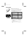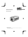
1
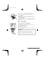
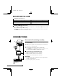
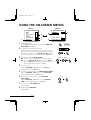
L53P4/US GB 1998, 3, 11
INSTRUCTION MANUAL
VCC-5974
COLOR CCD Camera
About this manual
•
Before installing and using the camera, please read this manual carefully. Be sure to
keep it handy for later reference.
SANYO INDUSTRIAL VIDEO
COLOR VIDEO CAMERA LIMITED WARRANTY
OBLIGATIONS
In order to obtain warranty service, the product must be delivered to and picked up from an Authorized Sanyo Service Center
at the user’s expense, unless specifically stated otherwise in this warranty. The names and addresses of Authorized Sanyo
Service Centers may be obtained by writing to SFS Corporation, SFC’s warranty administrator, at any of the addresses listed
below, or by calling (toll-free) 1-800-421-5013.
New Jersey Office
210 Riser Road
Little Ferry, NJ 07643
I,Af g .,E-4213.3.43 621-apick4Af nSzeYTy sE eg .,E-4213.3.43 621-a5 gUci4213.3wtrsey Off-NDUSTRIAL 0uB c, or r ey h hEIcRso igwtrCh 38076DUS213R6DU-26.16U-2
L53P4/US GB 1998, 3, 11
Depending on the conditions of use,
installation and environment, please be sure
to make the appropriate settings and
adjustments. If you need help with installation
and/or settings, please consult your dealer.
FEATURES
• Built-in interline transfer method 1/3" CCD,
approx. 410,000 picture elements
• Low smear, anti-blooming, low lag, no
CONTENTS
•
INFORMATION TO USER ..................................2
PRECAUTIONS...................................................3
PARTS NAMES...................................................4
MOUNTING THE LENS ......................................7
CONNECTIONS ..................................................9
SETTINGS.........................................................10
USING THE ON-SCREEN MENUS .................... 13
ADJUSTMENTS................................................14
TROUBLESHOOTING.......................................26
MENU DISPLAY...............................................27
SPECIFICATIONS .............................................29
ACCESSORIES
1 C mount adaptor (5 mm).....................1 pc.
The C mount adaptor must be used to be
able to install a C mount lens on the
camera.
2 Lens iris plug (4-pin) .............................1 pc.
1
2
English
1
•
•
•
•
burning and no geometric distortion using
the CCD solid state image device.
100% solid state components giving
excellent immunity to shock and vibration
Not subject to interference from magnetic
or electrostatic fields
High sensitivity, minimum required
illumination is 0.9 lux (F1.2, AGC Gain:
High, incandescent lighting)
Horizontal resolution, more than 470 TV
lines
Power supply: 24 V AC operation
L53P4/US GB 1998, 3, 11
INFORMATION TO USER
Safety Guard
THIS SYMBOL INDICATES THAT
THERE ARE IMPORTANT
OPERATING AND
MAINTENANCE INSTRUCTIONS
IN THE LITERATURE
ACCOMPANYING THIS UNIT.
WARNING:
TO PREVENT THE RISK OF FIRE OR
ELECTRIC SHOCK , DO NOT EXPOSE THIS
APPLIANCE TO RAIN OR MOISTURE.
For the customers in Canada
This Class B digital apparatus meets all
requirements of the Canadian InterferenceCausing Equipment Regulations.
Pour la clientèle canadienne
This installation should be made by a qualified
service person and should conform to all local
codes.
2 English
ENGLISH
Cet appareil numerique de la Classe B respecte
toutes les exigences du Reglement sur le
material brouilleur du Canada.
This equipment has been tested and found
to comply with the limits for a Class B
digital device, pursuant to Part 15 of the
FCC Rules.
These limits are designed to provide
reasonable protection against harmful
interference in a residential installation.
This equipment generates, uses, and can
radiate radio frequency energy and, if not
installed and used in accordance with the
instructions, may cause harmful
interference to radio communications.
However, there is no guarantee that
interference will not occur in a particular
installation. If this equipment does cause
harmful interference to radio or television
reception, which can be determined by
turning the equipment off and on, the
user is encouraged to try to correct the
interference by one or more of the
following measures:
– Reorient or relocate the receiving
antenna.
– Increase the separation between the
equipment and receiver.
– Connect the equipment into an outlet
on a circuit different from that to which
the receiver is connected.
– Consult the dealer or an experienced
radio/TV technician for help.
This device complies with Part 15 of the
FCC Rules. Operation is subject to the
following two conditions: (1) This device
may not cause harmful interference, and
(2) this device must accept any
interference received, including
interference that may cause undesired
operation.
Changes or modifications not expressly
approved by Sanyo may void the user’s
authority to operate this camera.
L53P4/US GB 1998, 3, 11
PRECAUTIONS
In case of problem
Do not use the camera if smoke or a strange
odour comes from the unit, or if it seems not
to function correctly. Disconnect the power
cord immediately, and consult your dealer (or
a Sanyo Authorized Service Centre).
Do not open or modify
Do not open the cabinet, as it may be
dangerous and cause damage to the unit. For
internal settings and repairs, consult your
dealer (or a Sanyo Authorized Service Centre).
Do not put objects inside the unit
Make sure that no metal objects or flammable
substance get inside the camera. If used with
a foreign object inside, it could cause a fire,
short-circuits or damages.
If water or a liquid gets inside the camera,
disconnect the power cord immediately, and
consult your dealer (or a Sanyo Authorized
Service Centre). Be careful to protect the
camera from rain, sea water, etc.
Be careful when handling the unit
To prevent damages, do not drop the camera
or subject it to strong shock or vibration.
Install away from electric or magnetic
fields
If installed close to a TV, radio transmitter,
magnet, electric motor, transformer, audio
speakers the magnetic field they generate will
distort the image.
Protect from humidity and dust
To prevent damages to the camera, do not
install it where there is greasy smoke or
steam, where the dampness may get too
high, or where there is a lot of dust.
English
3
Protect from high temperatures
Do not install close to stoves, or other heat
generating devices, such as spotlights, etc., or
where it could be subject to direct sunlight, as
that could cause deformation, discoloration or
other damages.
Be careful when installing close to the ceiling,
in a kitchen or boiler room, as the
temperature may raise to high levels.
Install where the temperature range will stay
between –10˚C and 50˚C.
(no condensation)
Cleaning
• Dirt can be removed from the cabinet by
wiping it with a soft cloth. To remove
stains, wipe with a soft cloth moistened
with a soft detergent solution and wrung
dry, then wipe dry with dry soft cloth.
• Do not use benzine, thinner or other
chemical product on the cabinet, as that
may cause deformation and paint peeling.
Before using a chemical cloth, make sure
to read all accompanying instructions.
Make sure that no plastic or rubber
material comes in contact with the cabinet
for a long period of time, as that may
cause damage or paint peeling.
L53P4/US GB 1998, 3, 11
PARTS NAMES
1 Lens iris output connector (4 pin)
1
1
3
2
4
This 4-pin connector is used to send the DC control signal and
power supply to an auto-iris type lens.
2 Auto white balance push lock button (AWB LOCK)
3 Menu setting button (SET)
Connect the camera to the monitor, then press the SET button
for about 3 seconds to display the on-screen menu.
7
5
6
2
3
4
8
1
2
3 2
4 Cursor button (CURSOR)
j: Press this button to move the cursor up.
c: Press this button to move the cursor to the right, or to
turn the settings ON/OFF etc.
d: Press this button to move the cursor to the left, or to
turn the settings ON/OFF.
l: Press this button to move the cursor down.
5 Flange-back lock screw (FLANGE BACK LOCK)
6 Flange-back adjustment screw (FLANGE BACK ADJ.)
1
1 Shorter screws: M3 x 4
2 Longer screws: M3 x 6
3 Camera mounting
screw hole:
1/4"-20 UNC
7 Lens mount cap
The cap is installed to protect the lens mount section.
Remove the lens mount cap before installing a lens (sold
separately).
8 Camera installation bracket
The bracket can be fixed at the top or bottom of the camera.
When fixing the bracket, be sure to use the longer screws and
install the shorter screws on the opposite side to seal the
openings.
CAUTION:
When installing the camera support, select a location
that can support the total weight of the camera and
accessories.
4 English
L53P4/US GB 1998, 3, 11
PARTS NAMES
9 Camera setup section (under the cover)
This unit factory settings are as indicated below. These settings
are for when using a 1/3 inch CS mount DC (without EE internal
amplifier) type lens. However, if due to installation conditions or
environment the settings may need to be modified for best
results (see "SETTINGS"). To access the controls, remove the
cover fixing screw, then remove the cover.
9
Control name
a High speed electronic shutter
switches (ES)
SYNC FL AGC
ES
LL ON ON WB
BLC
ON AI
ON
4
5
6
7
1
2
3
1
2
3 INT OFF OFF 7
8
I
R
I
S
9 10
8 OFF EI
b Internal/Line lock switch (SYNC)
c Auto gain control switch (AGC)
d White balance switch (WB)
e Backlight compensation switch
Position
All OFF: 1/60 sec
INT
ON
all ON: ATW
ON
(BLC)
a
c e
g
b d f
f Electronic iris (EI)/
AI
Auto iris (AI) switch
g Auto-iris lens switch (A.I. LENS)
DC
Notes:
• When using a 1/2 or 2/3 inch C mount VIDEO (with EE
internal amplifier) auto-iris type lens, set the A.I. LENS switch
to the VIDEO position.
The settings entered in the camera setup section can be
displayed using the on-screen menu.
• If not using an auto-iris lens, make sure the BLC switch is set
to OFF.
L53P4/US GB 1998, 3, 11
F Video output connector (VIDEO OUT: BNC type)
G
H
F
Connect this connector to a device such as a VCR or monitor
with a VIDEO IN connector.
G External sync composite video signal input connector
I
(VBS IN: BNC type)
Connect to this connector the synchronizing signal output from
a synchronizing signal device or the composite signal of a video
distributor.
H Power indicator (POWER)
Comes on when the power to the camera is on.
I 24 V AC input terminal (24 V AC, GND)
With this camera use only the 24 V AC power adaptor model
No. VPT-115 available from Sanyo.
GND
AC
AC
Power supply connections
Use a 3 wire grounded cable (22 AWG or more), and connect as
shown by the illustration.
CAUTION:
• To prevent camera and/or AC adaptor failure, pay close
attention to polarity when making the connections.
• To prevent fire hazard any UL listed wire rated VW-1,
should be used for the 24 V AC cable input terminal.
6 English
L53P4/US GB 1998, 3, 11
PARTS NAMES
Flange-back adjustment
If the pick-up surface is not correctly positioned with relation to
the lens focal point, the picture will be out of focus (in particular
when using auto-iris power zoom lenses, sold separately). If that
is the case, adjust the flange-back position as described below.
1
1
2
ADJ.
1
LOCK
3
2
3
Using a + screwdriver, loosen the FLANGE BACK LOCK
screw (M2:+).
Set the zoom lens to the maximum telephoto position, set
the focus using the focus ring on the lens.
Set the zoom lens to the maximum wide angle position, set
the focus using the FLANGE BACK ADJ. screw.
Repeat steps 2 and 3, until the image stays in focus when
changing from a telephoto shot to a wide angle shot.
When the setting is complete, tighten the FLANGE BACK
LOCK screw.
MOUNTING THE LENS
Check the lens mount
Do not use a lens if the length “L” is more than 5 mm. That
may damage the camera and prevent proper installation.
Installation of a DC type auto-iris lens (sold
separately)
L
A 1/3 inch CS mount type lens without EE amplifier circuit that
only uses a DC power source. This camera can receive (the A.I.
LENS switch to the DC type) a CS mount type lens without the
need of an adaptor.
If the lens plug shape or wiring does not correspond, please
install the supplied plug as indicated in the pin layout table.
English
7
L53P4/US GB 1998, 3, 11
MOUNTING THE LENS
Installation of a VIDEO type auto-iris lens
(sold separately)
2 (A)
(B)
A 1/2 or 2/3 inch C mount type lens with EE amplifier circuit
that uses the video signal and a DC power source.
1
2
3
3
1
3
2
4
4
DC
VIDEO
4
Remove the lens mount cap.
Attach the supplied C mount adaptor (A) to the auto-iris
lens (B), then install the assembly on the camera.
Connect the lens plug to the LENS connector on the side of
the camera.
If the lens plug shape or wiring does not correspond to the
specifications below, connect the supplied plug as indicated.
• When using lenses from other makers, make sure that the
pins connections in the plug correspond to the ones of
the camera.
Refer to the lens specifications to check the pins
connections in the plug.
• If they are different than indicated, remove the original
plug and connect the supplied plug according to the
diagram.
Set the A.I. LENS switch in the camera setup section to the
VIDEO position.
Pin layout
1
3
DC type lenses
1 Brake coil (–)
2 Brake coil (+)
3 Drive coil (+)
2
4
4 Drive coil (–)
VIDEO type lenses
+12 V DC (50 mA max.)
Not used
Video output (1.0 Vp-p, high
impedance)
Ground (for video signal and DC
power)
8 English
L53P4/US GB 1998, 3, 11
MOUNTING THE LENS
Compatible auto-iris lenses
1/3 inch Sanyo DC type lens
VCL-CS8LY: Standard angle, f= 8 mm
VCL-CS4LY: Wide angle, f= 4 mm
VCL-CS2LY: Ultra-wide angle, f= 2.8 mm
1/2 or 2/3 inch VIDEO type lens
Standard angle, f= 9 mm
Telephoto angle, f= 12 mm
More telephoto angle, f= 16 mm
If using a VIDEO type auto-iris lens
• Set the ALC and LEVEL controls on the lens to adjust the iris. Normally the ALC volume should
be turned all the way to Av (Average).
• Depending on the type of lens used, the lens may not perform properly. In such a case, adjust
the LEVEL volume on the lens casing to correct.
CONNECTIONS
(A)
1
Basic connection for monitoring or recording
The peripheral devices (VCR, monitor, lens, etc.) and cables
are sold separately.
1
2
2
Make the video signal connection between the camera and
the monitor or time lapse VCR.
Insert the plug of this power cord into a wall outlet.
The POWER indicator (A) will light. Adjust the picture on the
monitor using the Brightness and Contrast controls.
Coaxial cable type and maximum length
• Cable type RG-59U (3C-2V), 250 m maximum.
• Cable type RG-6U (5C-2V), 500 m maximum.
• Cable type RG-11U (7C-2V), 600 m maximum.
CAUTION:
• The RG-59U type cable should not be run through electrical
conduits or through the air.
• Using CCTV/Video-grade coaxial cable.
(Video signal connections)
: VIDEO IN
: VIDEO OUT
English
9
SETTINGS
The illustration shows the factory default settings for the switches in the camera setup section.
Depending on the camera installation location and conditions of use, it may be necessary to select
other settings, without having to make adjustments. The selected settings can be confirmed using
the on-screen menu. If adjustments are required, they can be entered using on-screen adjustment
sub-menus (see ADJUSTMENTS, page 14).
ES
SYNC FL AGC
LL ON ON WB
1
2
3
1
2
3 INT OFF OFF 7
BLC
ON AI
ON
4
5
6
7
8
I
R
I
S
9 10
8 OFF EI
High speed electronic shutter (ES) setting
Normally, the three speed setting switches (1, 2 and 3) for the
high speed electronic shutter are all set to the OFF position. This
sets the electronic shutter speed to 1/60 sec. The three switches
in the camera setup section can be set as indicated in table A to
select one of the 8 speeds available.
Notes:
• When using the high speed electronic shutter, the BLC switch
must be set to the OFF position.
• Using the high speed electronic shutter indoors with low
lighting, will give darker pictures. In such a case, add some
lights to make sure the lighting is sufficient. If the lighting is
very bright, pay attention to the light angle in order to avoid
or minimize the smear phenomenon effect.
• If IRIS is set to EI (electronic iris mode), then the high speed
electronic shutter speed will not correspond to the set speed.
L53P4/US GB 1998, 3, 11
SETTINGS
Automatic Gain Control (AGC) setting
The automatic gain control can be turned ON or OFF using the
AGC ON/OFF switch (6) in the camera setup section.
ON: Auto gain control function on (setting used under
normal conditions) (see page 23).
GAMMA: ON (0.45), OFF (1)
AGC GAIN: NORMAL (30 dB), HIGH (36 dB)
OFF: Fixed gain
Note:
When the AGC switch is set to OFF, the GAMMA and backlight
compensation are automatically set to OFF, and the IRIS is set to
AI.
ON
OFF
White balance (WB) setting
Under normal conditions, the white balance is set to ATW (Auto
Tracing White-Balance). However, depending on the camera
installation location and conditions of use, the white balance
mode can be set using the two WB switches (7 and 8) in the
camera setup section (see table 1).
ATW: Initial setting. The initial value cannot be changed.
LOCK: The white balance is done automatically while the AWB
LOCK button is pressed, then it is locked when the button is
released.
PRESET: The white balance is done according to one of the three
preset modes. The preset modes can be adjusted manually in the
adjustment sub-menu (see page 21).
MODE 1: Setting for incandescent lighting (2660 ˚K).
MODE 2: Setting for indoors, fluorescent lighting (5100 ˚K).
MODE 3: Can be set for outdoors, sunlight (5100 ˚K).
MANUAL: Set to the initial value. The value can be changed
manually in the adjustment sub-menu (see page 22).
English
11
Table 1
ATW
7
8
AWB LOCK
LOCK
7
8
7
8
7
8
PRESET
MANUAL
L53P4/US GB 1998, 3, 11
Backlight compensation (BLC) setting
The backlight compensation ON/OFF is set using the BLC
ON/OFF switch (9) in the camera setup section.
ON: Default setting, backlight compensation function on.
However, depending on the camera installation location
and conditions of use, if the backlight compensation
function need to be set, with the BLC switch set to ON,
press the SET button to select one of PRESET (1, 2) or
MANUAL (1, 2) modes indicated below.
• PRESET 1 (Basic setting, see Fig. 1)
When the subject is dark and moving within the image, the
brightness control is done independently for the 5 windows
(W 0-4). This setting is recommended when the subject will
be moving across or within the image.
• PRESET 2 (Basic setting, see Fig. 2)
The windows are regrouped in 2 sections (W 1 and 4; and W
0, 2 and 3) and the lens iris is set automatically so that the
backlight correction is optimum for the section composed of
windows W 1 and 2. This setting is recommended when the
subject will be centred in the image.
• MANUAL 1 (or MANUAL 2) (Fig. 1, 3)
The size and position of window W 4, and the windows (W
0 - 4) distribution (WINDOW WEIGHTING) can be set
manually to control a bigger area of the screen (e.g. when
the subject will be moving in the screen area) and stored
under one of the two manual settings.
OFF: Fixed backlight compensation
Notes:
• The backlight compensation will operate when using an
auto-iris lens (DC or VIDEO type).
• If in the “MENU FOR ADJUSTMENT”, AGC is set to OFF, the
backlight compensation will not operate.
ON
OFF
W0=1
W2=10
W4=15
W1=5
Fig. 1
W0=0
W2=0
W4=15
W3=0
W1=15
Fig. 2
WINDOW WEIGHTING
W0
W1
W2
W3
W4(FIX)
1
1
3
3
15
PRESET
MENU END
OFF
END
Fig. 3
Iris level setting
The iris is set using the IRIS AI (Auto-Iris)/EI (Electronic Iris)
switch (10) in the camera setup section.
AI: Initial setting. When using a DC type auto-iris lens, the iris
level settings can then be entered in the adjustment
sub-menu (see page 17).
EI: Electronic iris mode setting.
Note: If the AGC switch is set to OFF, setting the IRIS switch to
EI will not set the electronic iris mode.
W3=10
AI
EI
12 English
L53P4/US GB 1998, 3, 11
USING THE ON-SCREEN MENUS
(Menu 1)
(Menu 2)
MENU FOR ADJUSTMENT
MENU FOR ADJUSTMENT
5
1
2
3
4
5
6
7
8
SYNC
IRIS
BLC
WHITE BALANCE
AGC
SHUTTER
INT
AI
ON
ATW
ON
60
WRITE PROTECT
ON
NEXT PAGE
END
2
3
4
8
6
CAMERA ID
APERTURE
OFF
WRITE PROTECT
ON
PREVIOUS PAGE
END
To display the menu
Press the SET button for about 3 seconds. The “MENU FOR
ADJUSTMENT” is displayed.
To switch between menus and selection
When the setting of a switch in the camera setup section is
changed, the corresponding sub-menu is displayed. To adjust
the values or settings, press the CURSOR (d or c) button to
select the desired value or setting, then press the SET button.
Initial values protection (WRITE PROTECT)
ON: Default setting. The initial values cannot be modified.
OFF: Press the CURSOR (d or c) button to select OFF, then
press the SET button. The write protection is cancelled
and the initial values can then be changed.
7
SET
INT
CURSOR
CURSOR
SET
CURSOR
To exit the menu
Press the CURSOR (j or l) button to select END (get it
flashing), then press the SET button.
To switch to the second page of the “MENU FOR ADJUSTMENT”
Press the CURSOR (j or l) button to select NEXT PAGE
(get it flashing), then press the SET button.
To switch back to the first page of the “MENU FOR
ADJUSTMENT”
Press the CURSOR (j or l) button to select PREVIOUS
PAGE (get it flashing), then press the SET button.
To enter a camera ID (CAMERA ID)
(See page 24).
Aperture display (APERTURE)
(See page 25).
English
13
CURSOR
(or j)
SET
SET
L53P4/US GB 1998, 3, 11
ADJUSTMENTS
To enter settings or adjustments for the camera it must be
connected to a monitor. The settings and adjustments are made
by ways of on-screen displays.
(Menu 1)
MENU FOR ADJUSTMENT
Concerning the WRITE PROTECT function
In order to protect the settings and adjustments the WRITE
PROTECT function is set to ON. If it is necessary to enter new
settings or adjustments, press the CURSOR (j or l) button to
select the WRITE PROTECT function setting, then press the
CURSOR (d or c) button to select OFF, then press the SET
button.
CURSOR
CURSOR
SYNC
IRIS
BLC
WHITE BALANCE
AGC
SHUTTER
INT
AI
ON
ATW
ON
60
WRITE PROTECT
OFF
NEXT PAGE
END
SET
CONTENTS OF ADJUSTMENTS
1. SYNC
1-1. V sync phase adjustment.................................................15
1-2. VBS phase adjustment .....................................................16
2. IRIS
2-1. Auto-iris level adjustment ...............................................17
3. BLC
3-1. Setting the light measuring area characteristics (size,
position and distribution) for the MANUAL 1 setting..... 18
3-2. BLC level adjustment for the PRESET 1 setting .............20
4. WHITE BALANCE
4-1. PRESET MODE 2 (indoors, fluorescent lighting) setting
adjustment ........................................................................21
4-2. MANUAL setting adjustment ..........................................22
5. AGC .................................................................23
6. CAMERA ID ....................................................24
7. APERTURE ......................................................25
14 English
L53P4/US GB 1998, 3, 11
ADJUSTMENTS
1. SYNC
1-1. V sync phase adjustment
When using a camera switcher to connect 2 cameras or more to
one monitor, there may be a vertical roll of the images when
switched. In such a case, set as described below.
1
Set the SYNC switch (4) to L-L.
The on-screen setting will automatically switch to L-L. Press
the CURSOR (j or l) button to select the on-screen L-L
setting (get it flashing), then press the SET button. The
adjustment sub-menu “ADJUSTMENT FOR L-L” will be
displayed.
CURSOR
LL
SET
INT
2
MENU FOR ADJUSTMENT
SYNC
IRIS
BLC
ADJUSTMENT FOR L-L
(V SYNC PHASE)
L-L
AI
ON
Switch the display on the monitor from camera 1 to camera 2.
Press the CURSOR (d or c) button until the vertical sync
phase is obtained. The on-screen marker (b) will move and
the adjustment value will flash according to the vertical sync
phase setting.
o------z------p 524
ADJUSTMENT FOR L-L
(V SYNC PHASE)
o------z------p 415
PRESET
END
CURSOR
1
Note:
When an adjustment is made, the PRESET setting will
automatically switch to OFF. To return to the initial value, just
return the PRESET setting to ON, then press the SET button.
3
When finished.
1 Press the CURSOR (j or l) button to select END (get it
flashing), then press the SET button to return to the
normal camera display, or
2 Press the CURSOR (j or l) button to select MENU (get
it flashing), then press the SET button to return to the
“MENU FOR ADJUSTMENT” display.
English
15
OFF
MENU
2
L53P4/US GB 1998, 3, 11
1-2. VBS phase adjustment
1
Connect a VBS signal source to the VBS IN connector on the
camera.
The on-screen setting will automatically switch to VBS. Press the
CURSOR (j or l) button to select the on-screen VBS setting
(get it flashing), then press the SET button. The adjustment
sub-menu “ADJUSTMENT FOR VBS” will be displayed.
ADJUSTMENT FOR VBS
CURSOR
SET
MENU FOR ADJUSTMENT
SYNC
IRIS
BLC
VBS
AI
ON
2
Press the CURSOR (d or c) button to adjust the horizontal phase
(H). The on-screen marker (b) will move and the adjustment value
will flash according to the horizontal phase setting.
When finished setting the horizontal phase (H), press the
CURSOR (l) button to select the sub-carrier (SC) phase.
3
Press the CURSOR (d or c) button to adjust the sub-carrier (SC)
phase. The on-screen marker (b) will move and the adjustment
value will flash according to the sub-carrier phase setting.
(PHASE)
H
SC
o------z------p 280
o------z------p 90
Note:
When an adjustment is made, the PRESET setting will
automatically switch to OFF. To return to the initial values, just
return the PRESET setting to ON, then press the SET button.
4
When finished.
(Refer to step 3 on page 15.)
Note:
If using a VS sync signal, the H sync phase adjustment is made by
following the same method as described for the “VBS phase
adjustment”.
16 English
L53P4/US GB 1998, 3, 11
ADJUSTMENTS
2. IRIS
2-1. Auto-iris level adjustment
1
Set the IRIS switch (10) to AI.
The on-screen setting will automatically switch to AI. Press the
CURSOR (j or l) button to select the on-screen AI setting
(get it flashing), then press the SET button. The adjustment
sub-menu “ADJUSTMENT FOR AI” will be displayed.
AI
CURSOR
SET
EI
2
MENU FOR ADJUSTMENT
SYNC
IRIS
BLC
INT
AI
ON
Press the CURSOR (d or c) button until the desired iris level
is obtained. The on-screen marker (b) will move and the
adjustment value will flash according to the iris level setting.
ADJUSTMENT FOR AI
(IRIS LEVEL)
o------z------p 23
ADJUSTMENT FOR AI
(IRIS LEVEL)
o------z------p
Note:
When an adjustment is made, the PRESET setting will
automatically switch to OFF. To return to the initial value, just
return the PRESET setting to ON, then press the SET button.
3
When finished.
(Refer to step 3 on page 15.)
Notes:
• If IRIS is set to EI (electronic iris mode), the SHUTTER setting
function will not operate.
• When the AGC switch is set to OFF the IRIS cannot be set to
EI.
English
17
PRESET
END
35
OFF
MENU
Example:
When the image is dark,
press the CURSOR (d or
c) button to move the
on-screen marker close to
the position indicated above.
L53P4/US GB 1998, 3, 11
3. BLC
3-1. Setting the light measuring area
characteristics (size, position and
distribution) for the MANUAL 1 setting
1
Set the BLC switch (9) to ON. The on-screen setting for BLC will
automatically switch to ON. Press the CURSOR (j or l) button
to select the on-screen ON setting (get it flashing), then press the
SET button. The adjustment sub-menu “ADJUSTMENT FOR BLC”
will be displayed.
ON
CURSOR
MENU FOR ADJUSTMENT
SET
SYNC
IRIS
BLC
OFF
2
INT
AI
ON
Press the CURSOR (d or c) button until MANUAL 1 is
selected, then press the SET button. The adjustment
sub-menu “SIZE” will be displayed.
ADJUSTMENT FOR BLC
BLC MODE
PRESET 1
ADJUSTMENT FOR BLC
(SIZE)
ADJUSTMENT FOR BLC
BLC MODE
MANUAL1
PRESET1_PRESET2_MANUAL1_MANUAL2
3
Press the CURSOR buttons to set the size of the area, then
press the SET button. The adjustment sub-menu “POSITION”
will be displayed.
CURSOR
CURSOR
ADJUSTMENT FOR BLC
(POSITION)
ADJUSTMENT FOR BLC
(SIZE) (p)
(SIZE)
CURSOR
CURSOR
(o)
4
ADJUSTMENT FOR BLC
SET
(l)
(j)
Press the CURSOR buttons to move (up, down, right, left) the area
to the desired position, then press the SET button. The adjustment
sub-menu “WINDOW WEIGHTING” will be displayed.
WINDOW WEIGHTING
ADJUSTMENT FOR BLC
(POSITION)
Note:
The WINDOW WEIGHTING default values are W0 : 1, W1 : 1, W2
: 3, W3 : 3, W4 : 15 (the value for W4 is fixed to 15 and cannot
be modified).
W0
W1
W2
W3
W4(FIX)
1
1
3
3
15
PRESET
END
OFF
MENU
L53P4/US GB 1998, 3, 11
ADJUSTMENTS
5
Press the CURSOR (j or l) button to select the desired
window (get its value flashing), then press the CURSOR (d
or c) button to set the desired value (maximum 15) for each
of the 4 windows 0, 1, 2 and 3.
Example: W0 : 5, W1 : 5, W2 : 10 and W3 : 10
WINDOW WEIGHTING
WINDOW WEIGHTING
W0
W1
W2
W3
W4(FIX)
5
1
3
3
15
W0
W1
W2
W3
W4(FIX)
5
5
3
3
15
W0
W1
W2
W3
W4(FIX)
5
5
10
3
15
PRESET
END
OFF
MENU
PRESET
END
OFF
MENU
PRESET
END
OFF
MENU
CURSOR
CURSOR
1_2_3_4_5...
CURSOR
3_4_5...
WINDOW WEIGHTING
W0
W1
W2
W3
W4(FIX)
5
5
10
10
15
PRESET
END
OFF
MENU
CURSOR
CURSOR
8_9_10...
Note:
When an adjustment is made, the PRESET setting will
automatically switch to OFF. To return to the initial value, just
return the PRESET setting to ON, then press the SET button.
6
WINDOW WEIGHTING
When finished.
(Refer to step 3 on page 15.)
English
19
CURSOR
CURSOR
6_7_8_9_10...
L53P4/US GB 1998, 3, 11
3-2. BLC level adjustment for the PRESET 1
setting
1
Set the BLC switch (9) to ON. The on-screen setting for BLC
will automatically switch to ON. Press the CURSOR (j or l)
button to select the on-screen ON setting (get it flashing),
then press the SET button. The adjustment sub-menu
“ADJUSTMENT FOR BLC” will be displayed.
ON
CURSOR
SET
OFF
2
3
MENU FOR ADJUSTMENT
SYNC
IRIS
BLC
INT
AI
ON
ADJUSTMENT FOR BLC
BLC MODE
PRESET1
Press the CURSOR (d or c) button until PRESET 1 is selected.
Press the CURSOR (l) button to select BLC LEVEL (get it
flashing), then press the SET button. The adjustment
sub-menu “BLC LEVEL” will be displayed.
ADJUSTMENT FOR BLC
ADJUSTMENT FOR BLC
(BLC LEVEL)
BLC MODE
PRESET1
o------z------p 15
BLC LEVEL
4
While looking at the image on the monitor, press the
CURSOR (d or c) button until the BLC level is obtained. The
on-screen marker (b) will move and the adjustment value will
flash according to the BLC level setting.
Note:
When an adjustment is made, the PRESET setting will
automatically switch to OFF. To return to the initial value, just
return the PRESET setting to ON, then press the SET button.
5
When finished.
(Refer to step 3 on page 15.)
Note:
The BLC level adjustments should be entered under the PRESET 1
or MANUAL 1 settings. The BLC level adjustments entered under
the PRESET 2 or MANUAL 2 settings will not be effective.
ADJUSTMENT FOR BLC
(BLC LEVEL)
o------z------p 20
PRESET
END
OFF
MENU
Example:
If the backlight
compensation (BLC)
correction is insufficient,
press the CURSOR (d or
c) button to move the
on-screen marker close to
the position indicated above.
20 English
L53P4/US GB 1998, 3, 11
ADJUSTMENTS
4. WHITE BALANCE
4-1. PRESET MODE 2 (indoors, fluorescent
lighting) setting adjustment
1
Set the WB switches to the PRESET mode (switch 7 to OFF
and switch 8 to ON).
The on-screen setting for WHITE BALANCE will automatically
switch to PRESET. Press the CURSOR (j or l) button to
select the on-screen PRESET setting (get it flashing), then press
the SET button. The adjustment sub-menu “ADJUSTMENT
FOR WB” will be displayed.
WB
SET
SYNC
IRIS
BLC
WHITE BALANCE
AGC
7 8
2
ADJUSTMENT FOR WB
MENU FOR ADJUSTMENT
CURSOR
INT
AI
ON
PRESET
ON
Press the CURSOR (d or c) button until MODE 2 is
selected, then press the SET button. The adjustment
sub-menu “OFFSET” will be displayed.
WB PRESET
MODE 1
ADJUSTMENT FOR WB
(OFFSET)
R
o------z------p 29
B
o------z------p189
ADJUSTMENT FOR WB
WB PRESET
3
MODE 2
Press the CURSOR (d or c) button to adjust the R (red)
offset. The on-screen marker (b) will move and the
adjustment value will flash according to the red offset setting.
When finished setting the red offset, press the CURSOR (l)
button to select B (blue).
Press the CURSOR (d or c) button to adjust the B (blue)
offset. The on-screen marker (b) will move and the
adjustment value will flash according to the blue offset setting.
Note:
When an adjustment is made, the PRESET setting will
automatically switch to OFF. To return to the initial values, just
return the PRESET setting to ON, then press the SET button.
4
When finished.
(Refer to step 3 on page 15.)
Note:
The OFFSET settings for MODE 1 and MODE 3 are made by
following the same method as described for MODE 2.
English
21
PRESET
END
OFF
MENU
4-2. MANUAL setting adjustment
1
Set the WB switches to the MANUAL mode (both switches 7
and 8 to OFF).
ADJUSTMENTS
5. AGC
1
2
Set the AGC switch (6) to ON.
The on-screen setting for AGC will automatically switch to
ON. Press the CURSOR (j or l) button to select the
on-screen ON setting (get it flashing), then press the SET
button. The adjustment sub-menu will be displayed.
Setting the GAMMA
Press the CURSOR (d or c) button to select ON or OFF,
according to the conditions described below.
ON (0.45): For natural looking images. The image signal is
compressed and this setting is recommended
under normal conditions.
OFF (1): The image signal is not compressed. This setting is
recommended when processing the images.
When finished setting the gamma, press the CURSOR (l) button
L53P4/US GB 1998, 3, 11
6. CAMERA ID
1
Press the CURSOR (j or l) button to select NEXT PAGE
(get it flashing), then press the SET button. The second page
of the “MENU FOR ADJUSTMENT” will be displayed.
(Refer to page 13.)
CURSOR
2
3
4
SET
SHUTTER
60
WRITE PROTECT
ON
NEXT PAGE
END
With the CAMERA ID ON setting flashing, press the SET
button. The sub-menu “CAMERA ID SETTING” will be
displayed.
The camera ID will be displayed. If no ID has been previously
entered, ?????? will be displayed.
To change or enter a camera ID, press the SET button again.
The input sub-menu “CAMERA ID SETTING” will be displayed.
6
7
ON
CAMERA ID SETTING
CAMERA ID IS
??????
CAMERA ID SETTING
ABCDEFGHIJKLM
NOPQRSTUVWXYZ
0123456789:-p
MENU
Example: To enter the camera ID S123AB
Press the CURSOR buttons to select the desired alphanumeric
character or symbol (i.e. S), then press SET. The first ? or
character in the camera ID will change to “S”.
Repeat the same method to enter the desired camera ID
(maximum of 6 characters or symbols).
Note:
The symbol c indicates a blank space. When entered in a camera
ID, it will be displayed as a blank space.
5
MENU FOR ADJUSTMENT
CAMERA ID
APERTURE
CAMERA ID IS
CAMERA ID SETTING
ABCDEFGHIJKLM
NOPQRSTUVWXYZ
0123456789:-p
MENU
CAMERA ID IS
When finished entering the camera ID.
Press the CURSOR (d or c) button to select MENU (get it
flashing), then press the SET button to return to the “MENU
FOR ADJUSTMENT” display.
To correct the entered camera ID, repeat steps 2 to 5.
When finished.
Press the CURSOR (j or l) button to select END (get it
flashing), then press the SET button to return to the normal
camera display.
??????
S123AB
MENU FOR ADJUSTMENT
CAMERA ID
APERTURE
ON
WRITE PROTECT
ON
PREVIOUS PAGE
END
24 English
L53P4/US GB 1998, 3, 11
ADJUSTMENTS
7. APERTURE
1
Press the CURSOR (j or l) button to select NEXT PAGE
(get it flashing), then press the SET button. The second page
of the “MENU FOR ADJUSTMENT” will be displayed.
CURSOR
2
3
SET
SHUTTER
60
WRITE PROTECT
OFF
NEXT PAGE
END
Press the CURSOR (j or l) button to select APERTURE (get
it flashing), then press the SET button. The adjustment
sub-menu “ADJUSTMENT FOR APERTURE” will be displayed.
Press the CURSOR (d or c) button to adjust the aperture
setting (0 to 15 range). The on-screen marker (b) will move
and the adjustment value will flash according to the aperture
setting.
At this time the menu display will be cancelled, and you
cannot return from this display to the menu display. (This
happens even if the PRESET setting is set to ON.) To return to
the camera display, use the CURSOR buttons to select END
(get it flashing), then press the SET button.
A higher setting value will give a sharp pictures, a lower
setting value will give a soft pictures.
Note:
When an adjustment is made, the PRESET setting will
automatically switch to OFF. To return to the initial values, just
return the PRESET setting to ON, then press the SET button.
4
When finished.
(Refer to step 3 on page 15.)
English
25
MENU FOR ADJUSTMENT
CAMERA ID
APERTURE
ON
ADJUSTMENT FOR APERTURE
o------z------p 6
ADJUSTMENT FOR APERTURE
o------z------p 9
PRESET
END
OFF
L53P4/US GB 1998, 3, 11
TROUBLESHOOTING
Before taking the camera for repairs, please check below to make sure that the camera is used
correctly. If it still does not perform correctly, please consult your dealer or a Sanyo Authorized
Service Centre.
No picture on the monitor screen
Is the power turned on to all connected devices? Is the voltage correct?
Are all the signal connecting cables correctly connected?
Is the lighting sufficient?
Has the lens cap been removed?
Is the lens type (DC or VIDEO) correctly selected?
Depending on the type of lens, the A. I. LENS switch must be set accordingly.
• Is the iris control correctly set?
A: When using a DC type lens, the CORSOR button should be adjusted.
B: When using a VIDEO type lens, the LEVEL volume (on the lens) should be adjusted.
•
•
•
•
•
•
•
•
•
The picture is not clear
Is the monitor correctly adjusted?
Is the flange-back position correctly set?
Is the lens focus correctly adjusted?
Are the lens surfaces clean?
If there is dust or finger prints on the lens, the image quality will deteriorate. To clean the lens
use a soft cloth or a commercially available lens cleaning set.
SERVICE
This camera is a precision instruments and if treated with care, will provide years of satisfactory
performance. However, in the event of a problem, the owner is advised not to attempt to make
repairs or open the cabinet. Servicing should always be referred to your dealer or Sanyo
Authorized Service Centre.
26 English
L53P4/US GB 1998, 3, 11
MENU DISPLAY
b SYNC ADJUSTMENT
☞ SW4: LL/INT
INT
VBS (insert VBS signal)
VS
SYNC
IRIS
BLC
WHITE BALANCE
AGC
SHUTTER
INT
AI
ON
ATW
ON
60
WRITE PROTECT
ON
NEXT PAGE
END
(insert VS signal)
L-L
MENU FOR ADJUSTMENT
b IRIS ADJUSTMENT
☞ SW10: AI/EI
AI
EI
ADJUSTMENT FOR AI
(IRIS LEVEL)
b BLC ADJUSTMENT
☞ SW9: ON/OFF
o------z------p 23
MENU FOR ADJUSTMENT
ON
CAMERA ID
APERTURE
ON
WRITE PROTECT
ON
PREVIOUS PAGE
END
OFF
b WHITE BALANCE SETTING
☞ SW7, 8: all ON
ATW
ADJUSTMENT FOR WB
LOCK
(ON/OFF)
WB PRESET
MODE1
PRESET
(OFF/ON)
MANUAL
(all OFF)
ADJUSTMENT FOR WB
(GAIN)
R o------z------p 86
b AGC SETTING
☞ SW6: ON/OFF
ON
B o------z------p 72
OFF
b SHUTTER SETTING
☞ SW1, 2, 3: all OFF 1/60 sec.
60
100
250
500
1000
(OFF/OFF/ON)
(OFF/ON/OFF)
(OFF/ON/ON)
(ON/OFF/OFF)
b CAMERA ID SETTING
☞ CURSOR button: ON/OFF
ON
OFF
b APERTURE ADJUSTMENT
☞ SET button: push
APERTURE
English
27
2000 (ON/OFF/ON)
4000 (ON/ON/OFF)
10000 (ON/ON/ON)
L53P4/US GB 1998, 3, 11
ADJUSTMENT FOR VS
ADJUSTMENT FOR VBS
(PHASE)
H o------z------p 280
ADJUSTMENT FOR L-L
(H SYNC PHASE)
(V SYNC PHASE)
o------z------p 280
o------z------p 518
SC o------z------p 90
ADJUSTMENT FOR BLC
ADJUSTMENT FOR BLC
(SIZE)
BLC MODE
PRESET1
PRESET2
MANUAL1
BLC LEVEL
MANUAL2
ADJUSTMENT FOR BLC
ADJUSTMENT FOR BLC
(BLC LEVEL)
(POSITION)
o------z------p 15
(OFFSET)
R
MODE2
------z------p 0
B o------z------p 255
WINDOW WEIGHTING
MODE3
(OFFSET)
W0
W1
W2
W3
W4(FIX)
R o------z------p 29
B o------z------p 189
1
1
3
3
15
(OFFSET)
R
------z------p 7
B o------z------p 255
GAMMA
ON
AGC GAIN
NORMAL
CAMERA ID SETTING
CAMERA ID IS
??????
HIGH
GAMMA
OFF
AGC GAIN
NORMAL
HIGH
CAMERA ID SETTING
ABCDEFGHIJKLM
NOPQRSTUVWXYZ
0123456789:-p
MENU
ADJUSTMENT FOR APERTURE
o------z------p 6
CAMERA ID IS
??????
28 English
L53P4/US GB 1998, 3, 11
SPECIFICATIONS
Camera:
Scaning system :
Interlace :
Image device :
Picture elements :
Effective picture elements :
Synchronizing system :
External sync :
Resolution :
Video output level :
Video S/N ratio :
Minimum required illumination :
(incandescent lighting)
Backlight compensation :
Iris function :
Electronic iris range :
Electronic shutter :
Flange-back :
White balance :
Gain control :
Gamma correction :
Lens mount :
Environmental conditions :
Power supply :
Power consumption :
Weight :
Dimensions: mm
NTSC standard TV system (525 TV lines, 30 frames/sec.)
PLL 2:1 interlace
1/3 inch solid state image device CCD
811 (H) x 508 (V)
768 (H) x 494 (V)
Internal sync, Line lock manually switchable/External sync
VBS or VS signal (Genlock, Automatic switching)
470 TV lines horizontally, 350 TV lines vertically
1.0 Vp-p/75 ohms, composite
More than 48 dB (AGC switch ON: Normal),
More than 50 dB (AGC switch OFF)
Approx. 2 lux with a F 1.2 lens (AGC ON: Gain Normal, 50 IRE),
Approx. 0.9 lux with a F 1.2 lens (AGC ON: Gain High, 50 IRE)
Manual ON/OFF switching, Active-zone light measuring
system (Active when using an auto-iris lens)
Manual Electric iris (EI)/Auto iris (AI) switching
2 lux to 100,000 lux (F 1.2, lens)
2.7 lux to 130,000 lux (F 1.4, lens)
8 speeds, selectable by switches:
(1/60, 1/100, 1/250, 1/500, 1/1000, 1/2000, 1/4000,
1/10000 sec.)
12.5 mm ± 0.5 mm
ATW/AWB LOCK/PRESET/MANUAL switching
Manual ON (Normal: 30 dB, Hi: 36 dB)/OFF switching
Manual ON (γ = 0.45)/OFF (1) switching
CS mount (or C mount with the supplied adaptor)
Temperature: –10˚C ~ +50˚C
Humidity: less than 90% (no condensation)
24 V AC (± 4 V), 60 Hz
Approx. 3.4 W
Approx. 330 g (without lens)
108.5
99.5
1.5
56
45
11
1/4”–20 UNC
12
22
28
Features and specifications are subject to change without prior notice or obligations.
English
29