1
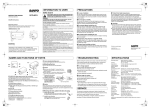
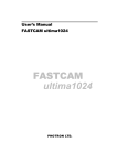
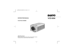
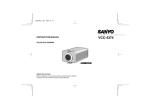
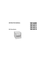
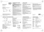
e_l5an4_us.fm Page 1 Wednesday, July 16, 2003 5:37 PM
INFORMATION TO USER
PRECAUTIONS
Safety Guard
THIS SYMBOL INDICATES THAT THERE ARE IMPORTANT
OPERATING AND MAINTENANCE INSTRUCTIONS IN THE
LITERATURE ACCOMPANYING THIS UNIT.
VCC-4344
INSTRUCTION MANUAL
J
(Warranty attached)
WARNING:
TO PREVENT THE RISK OF FIRE OR ELECTRIC SHOCK, DO NOT
EXPOSE THIS APPLIANCE TO RAIN OR MOISTURE.
COLOR CCD camera
For the customers in Canada
This Class B digital apparatus complies with Canadian ICES-003.
About this manual
Before installing and using the camera, please read this manual
carefully. Be sure to keep it handy for later reference.
Pour la clientèle canadienne
Cet appareil numerique de la Classe B est conforme a la norme NMB-003
du Canada.
This installation should be made by a qualified service person and should
conform to all local codes.
Dimensions: mm
136
67
1
126.5
54
11
15.4
28
1/4”–20 UNC
25.2
Depending on the conditions of use, installation and
environment, please be sure to make the appropriate settings
and adjustments. If you need help with installation and/or
settings, please consult your dealer.
This equipment has been tested and found to comply with the limits for a Class
B digital device, pursuant to Part 15 of the FCC Rules.
These limits are designed to provide reasonable protection against harmful
interference in a residential installation. This equipment generates, uses, and
can radiate radio frequency energy and, if not installed and used in accordance
with the instructions, may cause harmful interference to radio communications.
However, there is no guarantee that interference will not occur in a particular
installation. If this equipment does cause harmful interference to radio or
television reception, which can be determined by turning the equipment off and
on, the user is encouraged to try to correct the interference by one or more of
the following measures:
Reorient or relocate the receiving antenna.
Increase the separation between the equipment and receiver.
Connect the equipment into an outlet on a circuit different from that to which
the receiver is connected.
Consult the dealer or an experienced radio/TV technician for help.
This device complies with Part 15 of the FCC Rules. Operation is subject to the
following two conditions: (1) This device may not cause harmful interference,
and (2) this device must accept any interference received, including interference
that may cause undesired operation.
Changes or modifications not expressly approved by Sanyo may void the user's
authority to operate this camera.
NAMES AND FUNCTIONS OF PARTS
J
J
Lens cap
Protects the lens from damage.
Make sure that no metal objects or flammable substances get
inside the camera. If used with a foreign object inside, it could
cause fire, short-circuits or damage. If water or liquid gets inside the
camera, disconnect the power cord immediately, and consult your
dealer or a Sanyo Authorized Service Center. Be careful to protect
the camera from rain, sea water, etc.
J
J
J
VIDEO OUT (video output terminal: BNC connector)
Connects to the VIDEO IN (video input) terminal on the VCR or monitor.
Q
Camera adjustment/setting panel
Contains camera adjustment dials and setting switches.
LENS (lens iris output terminal)
Used to connect the lens plug when the lens is attached.
c Brake coil (-)
d Brake coil (+)
e Drive coil (+)
f Drive coil (-)
Attaching the lens
Use a DC type auto-iris lens (sold separately).
Do not use a lens if length “L” is more than 5 mm.
Otherwise, it may damage the camera and prevent
proper installation.
When attaching a C mount lens, attach the lens to the
camera after inserting the C mount ring (option).
1 Remove the lens mount
cap from the camera.
2
2 Install the auto-iris lens.
3 Connect the lens plug to 3
the lens iris output
connector (LENS) on the
side of the camera.
1
CS mount type lens
J
Cleaning
Dirt can be removed from the cabinet by wiping it with a soft cloth.
To remove stains, use a soft cloth moistened with a soft detergent
solution and wrung dry, then dry by wiping with a soft dry cloth.
Do not use benzine, thinner or other chemical products on the
cabinet, as they may cause deformation and paint peeling. Before
using a chemical cloth, make sure to read all accompanying
instructions. Make sure that no plastic or rubber material comes
in contact with the cabinet for extended periods, as that may
cause damage or paint peeling.
Protect from humidity and dust
Printed on recycled paper
1AC6P1P2705-L5AN4/US (0307TR-SY)
If no image appears
Is the coaxial cable attached securely?
Are the power and voltage normal?
Has the iris of the lens inside the camera been adjusted correctly
(with the iris dial)?
Is there adequate illumination?
If the image is unclear
Is the lens in focus?
Is the lens dirty?
Dirt or fingerprints on the lens can adversely affect the image.
Gently wipe any dirt or fingerprints off the lens with a soft cloth or
lens cleaning paper and cleaning fluid (commercially available).
Is the monitor adjusted correctly?
SERVICE
L
Protect from high temperatures
Do not install close to stoves, or other heat generating devices,
such as spotlights, etc., or where it could be subject to direct
sunlight, as that could cause deformation, discoloration or other
damage.
Be careful when installing close to the ceiling, in a kitchen or boiler
room, as the temperature may raise to high levels. Install where the
temperature range will stay between -10°C (14°F) and 50°C
(122°F). (no condensation)
Install away from electric or magnetic fields
To prevent damage to the camera, do not install it where there is
greasy smoke or steam, where the humidity may get too high, or
where there is a lot of dust.
J
When installing the camera support, select a location that can support the
total weight of the camera and accessories.
J
If installed close to a TV, radio transmitter, magnet, electric motor,
transformer, or audio speakers, the magnetic field they generate
will distort the image.
Camera installation bracket
The bracket can be secured at the top or bottom of the camera. When
securing the bracket, use the long screws and use the short screws on the
opposite side to seal the openings.
c Short screws: M3 x 4
d Long screws: M3 x 6
e Camera mounting screw hole: 1/4”-20 UNC
POWER (power indicator)
Lights when the camera power is ON.
GND, AC24V, DC12V (ground terminal, 24V AC or 12V DC input
terminal)
Be careful when handling the unit
To prevent damage, do not drop the camera or subject it to strong
shock or vibration.
J
LINE PHASE (Line phase adjustment volume)
When using two cameras or more, the image on the monitor may roll
vertically when switching sources. This rolling can be minimized by turning
this volume.
Do not put objects inside the unit
Before sending the camera out for repair, check the items below.
If the problem persists after checking these items, contact your
place of purchase or a Sanyo Authorized Service Center.
Flange-back lock screw
CONTROL (Manual color/black and white setting terminal)
G (ground) terminal
C (color) terminal
B (black and white) terminal
Do not open or modify
Do not open the cabinet, as it may be dangerous and cause
damage to the unit. For internal settings and repairs, consult your
dealer or a Sanyo Authorized Service Center.
TROUBLESHOOTING
Flange-back adjustment lever
GCB
In case of problem
Do not use the camera if smoke or strange odors come from the
unit, or if it seems not to function correctly. Disconnect the power
cord immediately, and consult your dealer or a Sanyo Authorized
Service Center.
The camera is a precision instrument. Handle it carefully and
always follow the safety precautions. If the camera requires service,
never try to repair it yourself or open the casing.
For servicing, maintenance, or repairs, contact your place of
purchase or a Sanyo Authorized Service Center.
SANYO Electric Co., Ltd.
Printed in Japan
SPECIFICATIONS
Scanning system
: NTSC standard TV system
(525 TV lines, 30 frames/sec.)
: PLL 2:1 interlace
: 1/4 inch solid state image device CCD
: 537 (H) x 505 (V)
: 510 (H) x 492 (V)
Interlace
Image device
Picture elements
Effective picture
elements
Synchronizing system : Internal sync, Line lock manually switchable
Resolution
: 350 TV lines horizontally (color mode),
380 TV lines horizontally (B/W mode),
350 TV lines vertically
Video output level
: 1.0 Vp-p/75 ohms, composite
Video S/N ratio
: More than 48 dB
Minimum required
: Approx. 0.05 lux with a F 1.2 lens (B/W mode),
illumination
Approx. 0.9 lux with a F 1.2 lens (color mode),
(incandescent lighting) Approx. 0.02 lux with a F 1.2 lens (B/W mode, Gain: HI)
Day/Night
: AUTO/MANUAL (at CONTROL terminal)
Control terminal
: Manual color/black and white setting
Backlight
: MULTI/OFF switching
compensation
CENT/OFF switching
(Active when using an auto-iris lens)
Iris function
: EI/AI switching
Auto-iris lens output : DC output (variable DC level), 4-pin terminal
Electronic iris range : 0.9 lux to 45000 lux (F 1.2 lens: color mode)
Flange-back
: 12.5 mm ±0.5 mm
White balance
: ATW/Manual switching
Gain up
: HI (high)/ NOR (Normal) switching
Lens mount
: CS mount
Environmental
: Temperature: -10°C – +50°C
conditions
Humidity: less than 90% (no condensation)
Power supply
: 12 – 15 VDC/24 VAC, 60 Hz (±10%)
Power consumption : 3.2 W (with auto iris lens)
Weight
: Approx. 430 g (without lens)
Appearance and specifications are subject to change without prior notice.
e_l5an4_us.fm Page 2 Wednesday, July 16, 2003 5:37 PM
CONNECTIONS
Connections
24 V AC connection
1
DC12V
The electronic iris is suitable for normal indoor use. When switch 1 (IRIS)
is set to the up (EI) position, do not use an auto-iris lens.
If used under fluorescent light, the image may flicker. In such a case,
change to incandescent lighting or set switch 1 (IRIS) to the down (AI)
position and use an auto-iris lens.
When shooting bright subjects, pay attention to the light angle in order to
avoid or minimize the smear effect.
If conditions are outside the electronic iris operation range or more than
the maximum illumination, the CCD will be saturated. In that case, use
the auto iris lens.
12 V DC connection
3
GND
AC24V
Monitor
AC24V
GND
3
DC12V
2
2
Q
GCB
SHRP
Emphasizes object outlines.
NORM
Normal setting
Camera adjustment
Q
Flange-back lock
screw
2
1 2 3 4 5 6 7 8
3
1,4
LEVEL
HI
Increased sensitivity allows shots to be taken in dark
environments.
NORM
Normal setting
Making connections
1 Connect the camera and peripheral equipment.
2 Connect the power cable.
<When using a 24 V AC adapter>
Connect 3 wire grounded cable (use 18AWG+) to the ground (GND)
terminal as shown in Figure 1.
<When using a 12 V DC adapter>
Connect the cable as shown in Figure 2.
When connecting the power cable to the camera, check that the polarity
is correct.
To prevent a fire hazard use any UL listed wire rated VW-1 for the 24 V
AC cable input terminal.
Q
CONTROL terminal
C
B
Image
OFF
OFF
Auto
OFF
ON
Black and white
ON
OFF
Color
ON
ON
Auto
CONTROL
G C B
ON: Close OFF: Open
The maximum length of cable for the CONTROL terminal is 400 m
(AWG24).
During optical filter switching, even if the manual switching operation is
complete, you cannot determine if the image is color or black and white.
Manual switching will have to be performed one more time.
FLANGE-BACK ADJUSTMENT
If the pick-up surface is not correctly positioned with relation to the lens
focal point, the picture will be out of focus (in particular when using auto-iris
power zoom lenses, sold separately). If that is the case, adjust the flangeback position as described below.
focus using the focus ring on the lens.
3 Set the zoom lens to the maximum wide angle position and set the
4 5
Backlight compensation 3
4
This camera has two different backlight compensation functions: Normally
backlight compensation switch 4 and 5 are set to the down (OFF)
position. Change the backlight compensation switch settings depending on
the conditions.
LL (external sync)
Adjust PHASE dial to eliminate sync disturbance.
INT (internal sync)
Internal Sync
If image disturbance doesn’t disappear after adjusting the PHASE dial on
the second and subsequent cameras, adjust the PHASE dial on the first
camera. If the problem persists, check that all the devices have been
connected with the correct power cable polarity.
Color/black and white switch setting 8
This switch lets you select the timing of the automatic switching of the
optical filter to color image or black and white image, according to the
subject brightness.
H
For a brighter setting than L
L
Standard setting
When the power is turned off and then on, switching will restart from color.
Multi-spot metering
4 5
When there
is backlight
in the entire
screen
4 5
When there
is backlight
only in the
background
A sound of the optical filter may be heard when the color image or black
and white image is switched. Also, the image will be distorted (black lines
may appear on the screen). This is normal and does not indicate a
problem.
When using infrared lighting, and if there is a strong reflection on the
subject, the optical filter may switch from black and white to color mode.
The focus setting may be different in color and black and white mode.
Please check and adjust the focus setting in both modes.
If the background of the object is
extremely dark, the center of the object
may be too bright. In this case, set
center-weighted metering mode.
Center-weighted metering
Only the center of the image is metered
and backlight-compensated.
Q
Iris dial (lens iris) 151
If the entire image is too dark or too bright, adjust the LEVEL dial ( 11 ).
Do not set switches 4 and 5 both to
“ON”. Compensation will not be
performed correctly with this setting.
SANYO INDUSTRIAL VIDEO
COLOR VIDEO CAMERA LIMITED WARRANTY
focus using the flange-back adjustment lever.
4 Repeat steps 2 and 3, until the image stays in focus when
changing from a telephoto shot to a wide angle shot.
When the setting is complete, tighten the flange-back lock screw.
When the flange-back lock screw is completely tightened it will protrude
slightly as shown in the illustration (Fig. A).
Do not tighten the screw further.
CAMERA ADJUSTMENTS/SETTINGS
The power indicator (POWER) lights.
Connect each pin of the CONTROL terminal as indicated below, to set the
image to color or black and white manually. You can adjust the image by
remote control.
Color image setting
Connect the C (color) and the G (ground) pins.
Black and white setting
Connect the B (black and white) and the G (ground) pins.
Vertical sync disturbance may occur when a selector is used to switch
between multiple cameras connected to one monitor. To prevent vertical
sync disturbance, set to “LL.”
L (Low)
Closes the lens iris, making the entire image darker.
H (High)
Opens the lens iris, making the entire image brighter.
1 Using a + screwdriver, loosen the flange-back lock screw (M2:+).
2 Set the zoom lens to the maximum telephoto position and set the
3 Insert the power adapter plug into the wall outlet.
Color/black and white setting
Sync setting 7
Q
Q
The HI setting causes noise generation and a grainy image.
Supported coaxial cables
When using an RG-59U (3C-2V) cable, do not use it on piping or air
wiring.
Select the cable according to the distance between the devices you wish
to connect.
If you use a cable other than the types above, the image or sync signal
will be attenuated and will not be transmitted correctly.
Q
H
The camera comes pre-adjusted and ready to install at time of factory
shipment, but you may want to make adjustments or settings to adapt to the
operating conditions or installation environment.
If you have trouble adjusting the camera, contact your place of purchase or
a Sanyo Authorized Service Center.
Q
Iris setting 1
Change Iris setting when using either lens below.
EI
(for indoor use)
AI
When using a manual or fixed iris lens and the electronic iris
function is on.
* Set the lens aperture to the shortest F stop.
When using an auto-iris lens.
Compensation is performed automatically.
Gain control (AGC) 3
Fig. A
You can use any of the following coaxial cables:
RG-59U (3C-2V) Length: About 250 m max.
RG-6U (5C-2V)
Length: About 500 m max.
RG-11U (7C-2V) Length: About 600 m max.
ATW
• R (Red) dial 9 : Turn clockwise to augment screen red.
• B (Blue) dial 10 : Turn clockwise to augment screen blue.
LL (Line-Lock): Synchronizes the unit with power frequency.
AI NOR NOR OFF ATW INT L
What you need
Peripheral equipment (such as monitor, digital video recorder or timelapse VCR)
Cables for connecting peripheral equipment and camera (coaxial cables,
connecting plugs)
Power adapter (24 V AC or 12 V DC)
Q
VR302 VR303 VR301
RED BLUE L
CONNECTIONS
Q
IRIS AP GAIN BLC WB SYNC C-BW
EI SHRP HI M C M LL H
Lets you fine-tune the white balance manually.
WB
For adjusting the sensitivity of the camera. Use this setting for shooting in
dark environments.
ON
Digital video recorder
or time-lapse VCR
MANU
Figure 2
Flange-back adjustment
: VIDEO IN
: VIDEO OUT
Aperture (outline compensation) 2
If object outlines appear too strongly, set to “NORM”.
Figure 1
Q
White balance (color compensation) 5
6 5
9 10
5
Q
OBLIGATIONS
In order to obtain warranty service, the product must be delivered to and picked up from an
Authorized Sanyo Service Center at the user's expense, unless specifically stated otherwise in
this warranty. The names and addresses of Authorized Sanyo Service Centers may be obtained
by calling the toll-free number listed below.
For product operation, authorized service center referral, service assistance or problem
resolution, call
CUSTOMER INFORMATION 1-800-421-5013
Weekdays 8:30 AM – 5:00 PM Pacific Time
For accessories and/or parts, call
PARTS ORDER INFORMATION 1-800-726-9662
Weekdays 8:30 AM – 5:00 PM Pacific Time
THIS WARRANTY IS VALID ONLY ON SANYO PRODUCTS PURCHASED OR RENTED IN
THE UNITED STATES OF AMERICA, EXCLUDING ALL U.S. TERRITORIES AND
PROTECTORATES. THIS WARRANTY APPLIES ONLY TO THE ORIGINAL RETAIL
PURCHASER OR END-USER. THE ORIGINAL DATED BILL OF SALE, SALES SLIP OR
RENTAL AGREEMENT MUST BE SUBMITTED TO THE AUTHORIZED SANYO SERVICE
CENTER AT THE TIME WARRANTY SERVICE IS REQUESTED.
Subject to the OBLIGATIONS above and EXCLUSIONS below, SANYO Fisher Company
warrants this SANYO product against defects in materials and workmanship for the periods
specified below. SFC will repair or replace (at its option) the product and any of its parts which fail
to conform to this warranty. The warranty period commences on the date the product was first
purchased or rented at retail.
EXCLUSIONS
This warranty does not cover (A) the adjustment of customer-operated controls as explained in
the appropriate model's instruction manual, or (B) the repair of any product whose serial number
has been altered, defaced or removed.
This warranty shall not apply to the cabinet or cosmetic parts, batteries or routine maintenance.
This warranty does not apply to uncrating, setup, installation, removal of the product for repair or
reinstallation of the product after repair.
This warranty does not apply to repairs or replacements necessitated by any cause beyond the
control of SFC including, but not limited to, any malfunction, defect or failure caused by or resulting
from unauthorized service or parts, improper maintenance, operation contrary to furnished
instructions, shipping or transit accidents, modification or repair by the user, abuse, misuse,
neglect, accident, incorrect power line voltage, fire, flood or other Acts of God, or normal wear and
tear.
The foregoing is in lieu of all other expressed warranties and SFC does not assume or authorize
any party to assume for it any other obligation or liability.
SFC DISCLAIMS ALL OTHER WARRANTIES EXPRESS OR IMPLIED, WITH REGARD TO
THIS PRODUCT (INCLUDING THE WARRANTIES OF MERCHANTABILITY AND FITNESS). IN
NO EVENT SHALL SFC BE LIABLE FOR ANY SPECIAL, INCIDENTAL OR CONSEQUENTIAL
DAMAGES ARISING FROM THE OWNERSHIP OR USE OF THIS PRODUCT OR FOR ANY
DELAY IN THE PERFORMANCE OF ITS OBLIGATIONS UNDER THIS WARRANTY DUE TO
CAUSES BEYOND ITS CONTROL. SFC'S LIABILITY FOR ANY AND ALL LOSSES AND
DAMAGES RESULTING FROM ANY CAUSE WHATSOEVER, ARISING OUT OF OR IN
CONNECTION WITH THE SALE, USE OR OWNERSHIP OF THIS PRODUCT INCLUDING
WARRANTOR'S NEGLIGENCE, ALLEGED DAMAGED OR DEFECTIIVE GOODS, WHETHER
SUCH DEFECTS ARE DISCOVERABLE OR LATENT, SHALL IN NO EVENT EXCEED THE
PURCHASE PRICE OF THE PRODUCT.
ATTENTION
For your protection in the event of theft or loss of this product, please fill in the information below
for your own personal records.
Model No.
Serial No.
(Located on back or bottom side of unit.)
Purchase Price
LABOR
PARTS
IMAGE DEVICE
Date of Purchase
3 YEARS
3 YEARS
3 YEARS
Where Purchased