1
Owner’s Manual
Network Set-up and Operation
For Windows
Wired and Wireless Setting
Projector Set-up and Operation
Network Capture
Network Viewer
Moderator Function
This is the manual for the Network function.
Read this manual thoroughly to operate the Network function.
First, read the owner's manual of the projector to understand the basic operation of the
projector and the safety instructions.
The safety instructions in the owner's manuals should be followed strictly.
Compliance
This projector provides the wireless LAN module which complies with the module certification.
Federal Communications Commission Notice
This equipment has been tested and found to comply with the limits for a Class B digital device,
pursuant to part 15 of the FCC Rules. These limits are designed to provide reasonable protection
against harmful interference in a residential installation. This equipment generates, uses and can
radiate radio frequency energy and, if not installed and used in accordance with the instructions, may
cause harmful interference to radio communications. However, there is no guarantee that interference
will not occur in a particular installation. If this equipment does cause harmful interference to radio
or television reception, which can be determined by turning the equipment off and on, the user is
encouraged to try to correct the interference by one or more of the following measures:
– Reorient or relocate the receiving antenna.
– Increase the separation between the equipment and receiver.
– Connect the equipment into an outlet on a circuit different from that to which the receiver is
connected.
– Consult the dealer or an experienced radio/TV technician for help.
Model Number : 1AV4U19B25500
Trade Name : Sanyo
Responsible party : SANYO FISHER COMPANY
Address : 21605 Plummer Street, Chatsworth, California 91311
Telephone No. : (818)998-7322
This device complies with Part 15 of FCC Rules and RSS-Gen of IC Rules. Operation is subject to the
following two conditions: (1) the device may not cause interference, and (2) the device must accept any
interference, including interference that may cause undesired operation of this device.
CAUTION: P
roperly shielded a grounded cables and connectors must be used for connection to host
computer and /or peripherals in order to meet FCC emission limits.
VGA cable with ferrite core must be used for RF interference suppression.
For Canadian Users
This Class B digital apparatus complies with Canadian ICES-003.
Cet apparei numérique de la classe B est conforme à la norme NMB-003 du Canada.
FCC Warning
Changes or modifications not expressly approved by the party responsible for compliance could void
the user’s authority to operate the equipment.
FCC RF Exposure Warning
- This transmitter must not be co-located or operated in conjunction with any other antenna or
transmitter.
- This equipment complies with FCC/IC radiation exposure limits set forth for uncontrolled equipment
and meets the FCC radio frequency (RF) Exposure Guidelines in Supplement C to OET65 and RSS-102
of IC radio frequency (RF) Exposure rules. This equipment should be installed and operated with at
least 20cm and more between the radiator and person’s body (excluding extremities: hands, wrists,
feet and ankles).
The CE Mark is a Directive conformity mark of the
European Community (EC).
The Alert Mark is a Directive conformity mark of the
European Community.
Česky
[Czech]
Hereby, SANYO FISHER Sales (Europe) GmbH, declares that this WLAN Module (1AV4U19B25500) is in
compliance with the essential requirements and other relevant provisions of Directive 1999/5/EC.
SANYO FISHER Sales (Europe) GmbH, tímto prohlašuje, že tento WLAN Module (1AV4U19B25500) je
ve shodě se základními požadavky a dalšími příslušnými ustanoveními směrnice 1999/5/ES.
Dansk
[Danish]
Undertegnede SANYO FISHER Sales (Europe) GmbH, erklærer herved, at følgende udstyr WLAN
Module (1AV4U19B25500) overholder de væsentlige krav og øvrige relevante krav i direktiv 1999/5/EF.
English
Deutsch
[German]
Eesti
[Estonian]
Español
[Spanish]
Ελληνική
[Greek]
Français
[French]
Italiano
[Italian]
Latviski
[Latvian]
Lietuvių
[Lithuanian]
Hiermit erk lär t SANYO FISHER Sales (Europe) GmbH, dass sich das Gerät WL AN Module
(1AV4U19B25500) in Übereinstimmung mit den grundlegenden Anforderungen und den übrigen
einschlägigen Bestimmungen der Richtlinie 1999/5/EG befindet.
Käesolevaga kinnitab SANYO FISHER Sales (Europe) GmbH, seadme WLAN Module (1AV4U19B25500)
vastavust direktiivi 1999/5/EÜ põhinõuetele ja nimetatud direktiivist tulenevatele teistele
asjakohastele sätetele.
Por medio de la presente SANYO FISHER Sales (Europe) GmbH, declara que el WLAN Module
(1AV4U19B25500) cumple con los requisitos esenciales y cualesquiera otras disposiciones aplicables
o exigibles de la Directiva 1999/5/CE.
Μ Ε Τ Η Ν ΠΑ Ρ ΟΥ Σ Α SA N YO FI SH ER S a l e s (Eu r o p e) G m b H , ΔΗ Λ Ω Ν ΕΙ ΟΤ Ι W L A N M o d u l e
(1AV4U19B25500) ΣΥΜΜΟΡΦΩΝΕΤΑΙ ΠΡΟΣ ΤΙΣ ΟΥΣΙΩΔΕΙΣ ΑΠΑΙΤΗΣΕΙΣ ΚΑΙ ΤΙΣ ΛΟΙΠΕΣ ΣΧΕΤΙΚΕΣ
ΔΙΑΤΑΞΕΙΣ ΤΗΣ ΟΔΗΓΙΑΣ 1999/5/ΕΚ.
Par la présente SANYO FISHER Sales (Europe) GmbH, déclare que l’appareil WLAN Module
(1AV4U19B25500) est conforme aux exigences essentielles et aux autres dispositions pertinentes de
la directive 1999/5/CE.
Con la presente SANYO FISHER Sales (Europe) GmbH, dichiara che questo WLAN Module
(1AV4U19B25500) è conforme ai requisiti essenziali ed alle altre disposizioni pertinenti stabilite dalla
direttiva 1999/5/CE.
Ar šo SANYO FISHER Sales (Europe) GmbH, deklarē, ka WLAN Module (1AV4U19B25500) atbilst
Direktīvas 1999/5/EK būtiskajām prasībām un citiem ar to saistītajiem noteikumiem.
Šiuo SANYO FISHER Sales (Europe) GmbH,deklaruoja, kad šis WLAN Module (1AV4U19B25500)
atitinka esminius reikalavimus ir kitas 1999/5/EB Direktyvos nuostatas.
H i e r b i j ve r k l a a r t SAN YO FI SH ER S a l e s (Eu r o p e) G m b H , d at h e t to e s te l W L AN M o d u l e
Nederlands
(1AV4U19B25500) in overeenstemming is met de essentiële eisen en de andere relevante bepalingen
[Dutch]
van richtlijn 1999/5/EG.
Hawnhekk, SANYO FISHER Sales (Europe) GmbH, jiddikjara li dan WLAN Module (1AV4U19B25500)
Malti
jikkonforma mal-ħtiġijiet essenzjali u ma provvedimenti oħrajn relevanti li hemm fid-Dirrettiva
[Maltese]
1999/5/EC.
Magyar
Alulírott, SANYO FISHER Sales (Europe) GmbH, nyilatkozom, hogy a WLAN Module (1AV4U19B25500)
[Hungarian] megfelel a vonatkozó alapvetõ követelményeknek és az 1999/5/EC irányelv egyéb elõírásainak.
Niniejszym SANYO FISHER Sales (Europe) GmbH, oświadcza, że WLAN Module (1AV4U19B25500)
Polski
jest zgodny z zasadniczymi wymogami oraz pozostałymi stosownymi postanowieniami Dyrektywy
[Polish]
1999/5/EC.
Português SANYO FISHER Sales (Europe) GmbH, declara que este (1AV4U19B25500) está conforme com os
[Portuguese] requisitos essenciais e outras disposições da Directiva 1999/5/CE.
Slovensko SANYO FISHER Sales (Europe) GmbH, izjavlja, da je ta (1AV4U19B25500) v skladu z bistvenimi
[Slovenian] zahtevami in ostalimi relevantnimi določili direktive 1999/5/ES.
Slovensky SANYO FISHER Sales (Europe) GmbH, týmto vyhlasuje, že (1AV4U19B25500) spĺňa základné
požiadavky a všetky príslušné ustanovenia Smernice 1999/5/ES.
[Slovak]
Suomi
SANYO FISHER Sales (Europe) GmbH, vakuuttaa täten että (1AV4U19B25500) tyyppinen laite on
direktiivin 1999/5/EY oleellisten vaatimusten ja sitä koskevien direktiivin muiden ehtojen mukainen.
[Finnish]
Härmed int ygar SANYO FISHER Sales (Europe) GmbH, at t denna (1AV4U19B2550 0) står I
Svenska
överensstämmelse med de väsentliga egenskapskrav och övriga relevanta bestämmelser som
[Swedish]
framgår av direktiv 1999/5/EG.
Islenska
Hér með lýsir SANYO FISHER Sales (Europe) GmbH, yfir því að (1AV4U19B25500) er í samræmi við
[Icelandic] grunnkröfur og aðrar kröfur, sem gerðar eru í tilskipun 1999/5/EC.
Norsk
SANYO FISHER Sales (Europe) GmbH, erklærer herved at utstyret (1AV4U19B25500) er i samsvar med
[Norwegian] de grunnleggende krav og øvrige relevante krav i direktiv 1999/5/EF.
Safety instructions
CAUTION IN USING THE PROJECTOR VIA NETWORKS
● When you find a problem with the projector, remove the power cable immediately and inspect
the unit. Using the projector with failure may cause fire or other accidents.
● If you remotely use the projector via networks, carry out a safety check regularly and take
particular care to its environment. Incorrect installation may cause fire or other accidents.
CAUTION IN USING NETWORK FUNCTION
● SANYO Electric Co., Ltd. assumes no responsibility for the loss or damage of data, or damage of
the computer caused by using this projector. Making back-up copies of valuable data in your
computer is recommended.
Caution about Radio Wave
This unit operates in 2.4 GHz band, the same frequency band used for industrial, scientific, and medical
equipment (such as pacemaker), as well as amateur radio stations.
Please read “Safety Instructions” section and make sure the following cautions.
1. Be sure that there are no other devices in the area that may use the same frequency band as
Projector.
2. If any other devices are causing radio interferences, change the communication frequency channel
or move to other location.
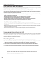
Trademarks and Copyright
Microsoft, Windows, and Internet Explorer are either registered trademarks or trademarks of Microsoft
Corporation in the United States and/or other countries.
Netscape Navigator and Netscape Communicator are registered trademarks or trademarks of Netscape
Communications Corporation in the United States and other countries.
Pentium is a registered trademark of Intel Corp. in the United States.
Each name of corporation or product in this Owner’s Manual is either a registered trademark or a
trademark of its respective corporation.
Notes
- The contents of this manual are subject to change without notice.
- You may not copy the printed materials accompanying with the software.
- We shall not be responsible for any damages caused by reliance on this manual.
Expression/Abbreviation
The OS of the computer and the Web browser described in this manual is Windows XP Professional and
Internet Explorer 6.0. In case of another OS or Web browser, some instruction procedures may differ
from the actual operation depending on your computer environment.
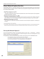
Use of this manual
This manual does not provide the description of basic operation and functions for computer, web
browser, projector and network. For instructions about each piece of equipment or application
software, please refer to the respective booklet.
Table of contents
Compliance..........................................................................................................................................................2
Safety instructions.............................................................................................................................................4
Table of contents................................................................................................................................................5
Operating environment and configuration..............................................................................................8
Required operating environment for computers...............................................................................8
Network specifications of the projector.................................................................................................9
Useful guide to the network function........................................................................................................10
How to project the computer screen’s image via the network......................................................10
ow to setup or control the projector by using a PC via the network........................................10
H
How to use all functions concerning the network.............................................................................10
1. About LAN functions.....................................................11
LAN functions and the features.................................................................................................................12
Image projecting system via LAN.............................................................................................................12
An example of the connection..................................................................................................................13
LAN connection modes................................................................................................................................14
2. Setup procedures..........................................................17
Installing the software..................................................................................................................................19
3. N
ames and functions of the operation screen............23
Network connection standby display.....................................................................................................24
Network Capture 5 window........................................................................................................................25
4. Wired LAN configurations............................................27
Connecting to the LAN line........................................................................................................................28
Network environment settings.................................................................................................................28
Confirming the operation............................................................................................................................30
Network PIN code...........................................................................................................................................32
Network information.....................................................................................................................................32
Wired factory default....................................................................................................................................33
Wired LAN factory default settings..........................................................................................................34
5. Wireless LAN configurations........................................35
Setting the network environment............................................................................................................36
Setting procedures........................................................................................................................................36
Configuring security with the projector.................................................................................................38
Easy wireless setting......................................................................................................................................41
Network PIN code...........................................................................................................................................42
Network information.....................................................................................................................................42
Wireless factory default................................................................................................................................42
WIRELESS indicator display.........................................................................................................................43
Wireless LAN factory default settings.....................................................................................................44
6. Basic setting and operation..........................................45
Starting up the Browser...............................................................................................................................46
How to use the setting page......................................................................................................................48
Initial setting.....................................................................................................................................................50
Network configuration.................................................................................................................................53
Configuring wireless LAN setting and security setting....................................................................55
E-mail setting...................................................................................................................................................57
SNMP setting....................................................................................................................................................61
7. Controlling the projector.............................................65
Power control and status check................................................................................................................66
Controls..............................................................................................................................................................68
PC adjustment.................................................................................................................................................72
Setting up the projector...............................................................................................................................73
Timer setting....................................................................................................................................................76
Projector information....................................................................................................................................79
Multi-control....................................................................................................................................................81
8. Network capture functions..........................................87
About Network Capture function.............................................................................................................88
Using the Real Time Capture......................................................................................................................91
Using the Network Communication........................................................................................................96
How to use the Network communication............................................................................................100
Network Communication operation and change of state...............................................................103
Executing the forcing mode.......................................................................................................................104
Moderator function.......................................................................................................................................105
Preparation for using the moderator function....................................................................................106
Using the moderator function...................................................................................................................107
Moderator's password setting up.............................................................................................................108
Unregister moderator status......................................................................................................................108
Error information............................................................................................................................................109
Playing the movie files..................................................................................................................................110
9. Network Viewer functions............................................113
Creating the available data [Network Viewer 5]..................................................................................114
Creating a program file [Program Editor]...............................................................................................119
Using the Network Viewer function.........................................................................................................124
Use of the projector as FTP server............................................................................................................130
10. N
etwork Projector [Windows Vista]...........................133
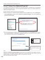
Use of "Connect to a Network Projector"...............................................................................................134
11. Appendix......................................................................137
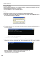
Use of telnet.....................................................................................................................................................138
Web browser setting.....................................................................................................................................140
Firewall setting................................................................................................................................................145
Troubleshooting.............................................................................................................................................146
Terminology.....................................................................................................................................................152
Operating environment and configuration
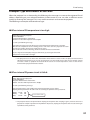
Required operating environment for computers
When operating the projector via the networks, computers should meet the operating environment
below.
Microsoft Windows 2000 or
Microsoft Windows XP or
Microsoft Windows Vista (32bit version)
OS
CPU
Pentium 3 ; 1GHz or higher
(more than 2GHz is recommended) for Windows 2000
or Windows XP
Pentium 4 ; 3GHz or higher for Windows Vista
Memory
256MB or more for Windows 2000 or Windows XP
1GB or more for Windows Vista
Free HDD Space
Screen Resolution
Communication Protocol
Network
Correspond
Wireless LAN
Wired LAN
Browser Application
100MB
Required to support any of VGA (640 x 480), SVGA
(800 x 600), XGA (1024 x 768),
The color number should be either 16 bit (65536
colors) or 24/32 bit (16.77 million colors).
TCP/IP
Correspond to IEEE802.11b/g, IEEE802.11n (Draft 2.0)
Correspond to 100BASE-TX (100Mbps)
/10BASE-T (10Mbps)
Microsoft Internet Explorer Ver.4.0 or later
Netscape Communications Netscape Communicator
Ver.6.0 or later
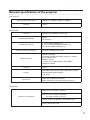
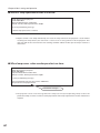
Network specifications of the projector
LAN Terminal
Data communication speed
100Base-TX (100Mbps)/10Base-T (10Mbps)
Protocol
TCP/IP
Interface
IEEE802.11b/g, IEEE802.11n(Draft 2.0)
Wireless LAN
Communication Mode
Data Transfer Speed
Wireless Frequency (Channel)
Modulation Form
AdHoc,
Infrastructure
1/2/5.5/11Mbps (IEEE802.11b)
6/9/12/18/24/36/48/54Mbps (IEEE802.11g)
Max speed 150Mbps (IEEE802.11n)
2412MHz–2462MHz (CH1–CH11)
IEEE802.11g OFDM
54/48Mbps 64QAM, 36/24Mbps 16QAM, 18/12Mbps
QPSK, 9/6Mbps BPSK
IEEE802.11b DSSS
11/5Mbps CCK, 2Mbps DQPSK, 1Mbps DBPSK
IEEE802.11n OFDM
Protocol
TCP/IP
Security
WEP 64Bit (Open/Shared) /WEP 128Bit (Open/Shared),
WPA-PSK(TKIP), WPA2-PSK(AES),
SSID, ESSID
Service area
about 30 m (without disturbance)
Differs according to the operating environment.
Compliance
JAPAN: VCCI ClassB,TELEC (Wireless)
Countries and Standards
USA: FCC Part15 Subpart C (Wireless)
FCC Part15 Subpart C, Class B
Canada: IC RSS-210 (Wireless), IC ICES-003 ClassB
Europe: R&TTE, EMC, LVD
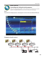
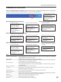
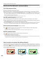
Useful guide to the network function
This manual describes the operation procedure of the projector’s network menu and the provided
application software for Windows users. Please refer to this manual depending on the situation.
l How to project the computer screen’s image via the network
To project the computer screen’s image via the network, you need to make a network setting in the
projector and connect the projector to the network, or if you use the supplied USB memory, you can
project the computer screen’s image via the network without making a network setting.
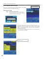
Check 1
Yes
Check 2
Yes
Did you make a network setting in the projector?
No
Project the image by using the Auto Capture program on the
supplied USB memory. (p.95)
Did you install the supplied application?
No
• Control by the projector (p.91, 94)
• Control by the web browser (p.91, 93)
• Use of "Connect to a Network Projector" in the Windows
Vista (p.134)
Project the image by using the Real Time Capture function in the
supplied ‘Network Capture 5’ application. (p.91, 92)
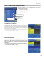
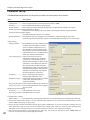
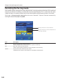
lH
ow to setup or control the projector by using a PC via
the network
To setup or control the projector via the network, you need to make a network setting in the projector
and connect the projector to the network.
Check
Did you make a network setting in the projector?
Yes
No
You cannot setup or control the projector via the network
without making a network setting in the projector. Please make
a network setting. [Wired LAN configurations (p.27-34)/Wireless
LAN configurations (p.35-44) ]
Setup or control the projector by controlling the web browser of the PC.
[Setup (p.45-64)/ Control p.65-86) ].
l How to use all functions concerning the network
To use all functions concerning the network of this projector, you need to make a network setting in the
projector and install the supplied application. Please follow the procedure on page 18.
10
Chapter
1
1. About LAN functions
This chapter describes the features, the mechanism,
and connection procedures of the LAN.
11
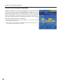
Chapter 1 About LAN functions
LAN functions and the features
This product is loaded with a LAN network function which enables you to project an image on the
computer through a projector via Network with dedicated software.
With the software, you can also manipulate the projecting image and the projector.
This software has functions below and you can use the projector under various network environments
to meet the wide-ranging needs of the operation.
• Accept both Wired and Wireless LAN environment. When the projector is operated via Wireless LAN,
there is no need for wire connection.
• Remove the burden of LAN settings. Easy LAN setting function is provided.
• One computer image can be projected up to 5 projectors simultaneously.
• Network capture function to project the computer's screen image through the projector.
• Remote function which allows you to operate the projector from a distance.
• Monitoring function for the projector operation.
• E-mail function which reports the operating status to your maintenance management.
• Network viewer function which remotely operates the image data on the server to project through
the projector.
• Moderator function with which the moderator can project the image on the participants’ computer
screen at the meetings or the classes.
• Multi control function which can operate multiple projectors (up to 100) simultaneously.
Image projecting system via LAN
The images are projected through an image capturing system which helps to project the faithful
computer images. With this system, you can use the product under various application environments
despite the differences of application software.
Flow of Image Transfer
1. Download the computer image with the dedicated software faithfully to the real image.
2. The downloaded data will be compressed to the digital signal and transferred to the projector via the
LAN (Wired or Wireless). (One computer can operate up to 5 projectors simultaneously.)
3. Digital signal will be reproduced into RGB image signal and will be projected by the projector.
✳ The image will be transferred to each projector. The time lag can occur between each projection.
CAUTION: This product does not correspond to the application with DirectX, MSOffice assistant, and video replay such as DVD.
12
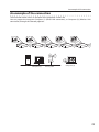
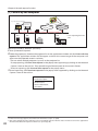
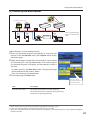
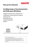
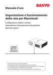
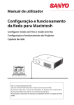
An example of the connection
An example of the connection
The illustration below shows an example of the projection via the LAN.
You can project the image on Computer (1) (Wired LAN connection), or Computer (2) (Wireless LAN
connection) through the selected projector .
2.0
1.5
1.0
0.5
0.0
2.0
1.5
1.0
0.5
0.0
2.0
1.5
1.0
0.5
0.0
Computer (1)
Access point
Computer (2)
13
Chapter 1 About LAN functions
LAN connection modes
Connection modes differ depending on the LAN and computer environments.
Connect appropriately for each environment.
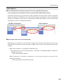
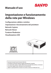
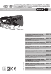
■ Wireless LAN, Infrastructure Communication Mode
Communicate over an access point between Wired LAN equipment and Wireless LAN equipment. Or,
communicate over an access point among multiple Wireless LAN equipment. Wireless LAN equipment
will select an access point to communicate SSID/ESSID modes. These communication modes are used
when both Wireless LAN and Wired LAN are used in the same network environment.
Computer (1) Computer (2)
Access point
Wireless communication mode
corresponded computer: Infrastructure
■ Wireless LAN, AdHoc Communication Mode
Communication mode between Wireless LAN equipment.
(Communication mode via SSID/ESSID)
Network Projector
Wireless communication mode :AdHoc
Wireless communication mode corresponded
computer: AdHoc
14
LAN connection modes
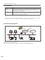
■ Wired LAN Communication Mode
Communicate via the LAN line.
Computer(1)
Computer(2)
Computer (3)
✳ Operate the computer mouse with the remote control.
When the projector’s remote control employs mouse operating function, you can operate the
computer by the remote control. To use the remote control, point to the projector. You do not
need to connect the USB cable to operate the computer mouse.
15
Chapter 1 About LAN functions
16
Chapter
2
2. Setup procedures
This chapter describes how to install the Network
Capture 5 software and how to set up the networks.
17
Chapter 2 Setup procedures
To use the projector via the networks, follow the setup procedures below.
Install the software on computers.
STEP 1
Install the software recorded in CD-ROM on each computer which will be operated.
Read following pages of this chapter to install.
Select Wired LAN or Wireless LAN then connect the
LAN and set the configuration.
STEP 2
Decide depending on the LAN environment.
Wired LAN............. Refer to “4. Wired LAN Configurations” (pp.27–34).
Wireless LAN........ Refer to “5. Wireless LAN Configurations” (pp.35–44).
Detailed LAN configurations need to be done with a browser later.
First, complete the Wired or Wireless LAN connection between computers and
projectors, then start browser configurations.
➔ “6. Basic setting and operation” (pp.45–64).
STEP 3
Network Configuration has completed.
Follow each chapter to project an image and operate the projector.
■ Operate and manage the projector ➔ “7. Controlling the projector” (pp.65-86)
➔ “Power Control and status check” (p.66)
➔ “Controls” (p.68)
➔ “PC adjustment” (p.72)
➔ “Setting up the projector” (p.73)
➔ “Timer setting” (p.76)
➔ “Projector information” (p.79)
➔ “Multi-control” (p.81)
■ Project an image on the computer ➔ “8. Network capture functions" (pp.87-110)
➔ “Use of real time capture” (p.91)
➔ “Use of network communication” (p.96)
➔ “Moderator function” (p.107)
■ Project an image on a network server ➔ “9. Network Viewer functions” (pp.113-130)
➔ “Create the available data” (p.114).
➔ “Create the program files” (p.119).
➔ “Project the image with network viewer function” (p.124)
* Even if Network Capture 5 is not installed into the computer, the wireless LAN can be set up with USB memory. (p.95)
18
Installing the software
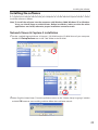
Installing the software
It is required to install the software into your computer to use the Network Capture function . Please
install the software as follows.
Note: To install the software into the computer with Windows 2000, Windows XP or Windows
Vista, you should logon as administrator. Before installation, make sure that the other
applications are closed, otherwise proper installation cannot be made.
Network Viewer & Capture 5 installation
1 Set the supplied Network Viewer & Capture 5 CD-ROM into the CD-ROM drive of your computer.
Double click SetupTool.exe icon in the "Tool" folder in the CD-ROM.
2 Select "English [United States]" from the pull-down menu on the "Choose Setup Language" window
and click OK button to start installing and then follow the installation wizards.
19
Chapter 2 Setup procedures
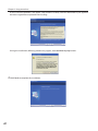
As the "License Agreement" will appear, read contents carefully and click Yes button if you agree to
the license agreement to proceed with installing.
During the installation, following window may appear, click Continue Anyway button.
3 Click Finish to complete the installation.
20
Installing the software
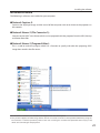
Installed software
The following 3 softwares are installed on your computer.
● Network Capture 5:
Captures the displayed image and the sound of the computer and serves them to the projector via
the network.
● Network Viewer 5 (File Converter 1):
Converts to the JPEG*1 data format which can be projected with the projector from the JPEG, bitmap
and Power Point files.
● Network Viewer 5 (Program Editor) :
This is a tool to make the program which has a function to specify and order the projecting JPEG
image data stored in the file servers.
* To uninstall these software, use "Add/Remove Program" from the control panel.
*1 This product supports the JPEG image format. This file is needed to convert to the optimized JPEG file by using the
File Converter 1 software previously. Refer to the item "Creating the available data [Network Viewer 5]"(+p.114)
about data converting for the projection.
21
Chapter 2 Setup procedures
File Converter 2 installation
1 Set the supplied Network Viewer & Capture 5 CD2
ROM into the CD-ROM drive of your computer.
Double click SetupDrv.exe icon in the "Driver"
folder in the CD-ROM.
Select "English [United States]" from the pull-down
menu on the language selection window and then
click Install button to start installing.
Installed software and places
Network Viewer 5 (File Converter 2) is installed in the "Printers and Faxes" folder in the "Control Panel".
● Network Viewer 5 (File Converter 2):
This is a kind of the printer driver to convert to the JPEG
data optimized to project by the projector from any of
the documents created by the application software.
22
* To uninstall Network Viewer 5 (File Converter 2), just delete the "Network Viewer 5(File Converter 2)" icon from the
"Printers and faxes" folder.
Chapter
3
3. Names and functions of the operation
screen
This chapter describes the functions of each part of the
operation screen.
23
Chapter 3 Names and functions of the operating screen
Network connection standby display
Turn on the projector and select either “Wired” or “Wireless” from the input menu of the projector.
The “Please wait...” message will be displayed on the screen. After short time, the network connection
standby display screen will appear as below. While the “Please wait...” message is shown, some
operations are invalid.
Network Connection Standby Display
24
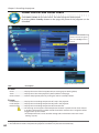
Network Capture 5 window
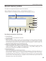
Network Capture 5 window
This software is to project the computer screen via the networks.
Select "All Programs" from the start menu --> Network Viewer & Capture 5" -->
"Network Capture 5", then following screen will appear. Then the program will start.
r
t
y
u
i
o
!0
q
w
!1
e
!2
!3
!4
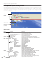
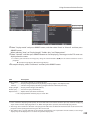
Parts Names and Functions of the Screen
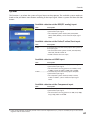
Search PJ button
Search the projector connected to the networks.
Specify IP button
When connected to a different segment network, the projector can not be retrieved automatically.
In that case, press this button, the "Search specified IP address list" window appears, and then
click Add button and enter the IP address directly to specify the projector in another window. The
registered multiple IP addresses can be searched at a time.
e Wireless easy setting button / Wireless easy release button
Configure the Wireless LAN setting just by clicking this button. (The setting will be stored as AdHoc
system) For details, refer to "5. Wireless LAN configurations"-->"Easy wireless setting" (p.41). To
restore the easy setting, press the Wireless easy release button.
r Network Projector List
Display all the projectors connected to the networks.
Show unoccupied projector as “On standby” and occupied projector as “Real time capturing” or "In
One-shot mode". When registered in a moderator’s group, "On Moderator mode" will be shown.
The indication of the status of use with "#" indicates that your computer is now using the network
capture function. After double-clicking on a projector name, the web browser gets activated and
q
w
the projector setup screen will be displayed.
25
Chapter 3 Names and functions of the operating screen
t Start communication button
Enter the Communication mode, and then , the capture edit window starts. The selected projector
shows the capture edit window.
y Play Movie files button
The play movie files window will appear.
u Start real time capture button
Capture (Project) the computer screen in real time. After the execution of "Start real time capture",
the application window disappears. • • • v
i One-shot capture button
Copy and capture (project) the computer screen without modification. After the execution of Oneshot capture, the application window disappears. • • • v
o Terminate capture button
Terminate the real time capture and the One-shot capture.
!0 Select capturing object button
It is possible to designate the window to capture individually. This button is disabled by default,
so the full screen is captured. It is possible to change the capturing object function setting at
parameter settings. For detail, refer to "Parameter set up" (p.90).
!1 Moderator registration button
Register a computer user as a moderator.
!2 Join moderator's group button
Join the moderator's group which is selected in the Network Projector list. It is not available if there
is no moderator registered.
!3 Parameter setup button
Activate the parameter setup window, and execute the connections setting, the image setting, and
the moderator's function setting. For detail, refer to "Parameter set up" (p.90).
!4 Volume adjust slider and Mute check box
Adjust the audio output from the real time capturing computer. The mute check box is checked by
default.
v To show the application window again, refer to the item "Commands on the task bar" (p.89).
Note on Windows Vista
When you use the Network Capture 5 software with Windows Vista, the warning dialog "User account
control" will appear. In that case, click Allow button to use it.
Using the multiple network adaptors
When your computer provides multiple network adaptors, the network adaptor selecting window will
appear each time the Network Capture 5 software starts. Select a network adaptor and check the "Set
network adaptor as default" and then click OK. To change the setting, refer to the item "Parameter set
up" (p.90).
26
Chapter
4
4. Wired LAN configurations
This chapter describes the preparation for Wired
LAN setting with projectors and how to set the LAN
environment.
27
Chapter 4 Wired LAN configurations
Setting procedures and contents differ depending on the LAN installation location.
When installing, consult your system administrator to set up the LAN appropriately.
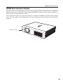
Connecting to the LAN line
Connect the shielded LAN cable to the LAN connection terminal of the projector.
ACT Lamp (Orange)
When the projector is
connected to the 100 BaseTX network, light or blink as
follows;
- Light when connecting to
the network.
- Blink when sending or
receiving the data.
LAN Connection
Terminal
LINK lamp (Green)
Light green when the
projector is connected to the
network.
LAN Cable**
** Please use a shielded LAN cable .
* When the LAN setting is “Off”, the two lamps will not be on.
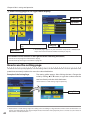
Network environment settings
Set the Wired LAN network through the projector menu. Detailed network settings will be made with
browser. Refer to “6. Basic setting and operation” (p45-64). First, complete the settings described in this
chapter before performing steps in “6. Basic setting and operation.”
Setting Procedure
1. Turn on the projector and select “Network” from the input menu of the projector.
2. Select “LAN mode select” in the Network menu, and press Point 8 or SELECT button.
3. S elect similar LAN environment among Wired1, 2 and 3 with the Point ed buttons. Then the Menu
will disappear, the “Please wait...” message will appear, and switching operation will start. Switching
will take a while and after completing the operation, the “Ready for use” message will appear, and the
projector’s LINK/ACT Lamp will be on or blink.
28
Network environment setting
4. Select "Network setting" in the Network menu and press SELECT button, and then the LAN setting
screen will appear and selected LAN settings will be displayed. Adjust each item to the setting
environment. Consult your system administrator about the detailed settings.
Move among the items with the Point ed buttons and press SELECT button, move among the
columns with Point 7 8 buttons, adjust the figures with Point ed buttons, and then press SELECT
button to set.
5. After completing all the settings, select “Set” and press SELECT button. Now, all procedures have been
done. To cancel the adjusted settings, select "Cancel" and press SELECT button.
To confirm whether the settings are correct, follow the procedures described from the next page.
You can confirm the LAN settings you have made from “Network Information” (p.32). In such cases
that the LAN cannot be connected, see this screen.
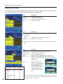
Network setting
DHCP: Off
DHCP: On
Item
Description
DHCP...........................Sets DHCP function On or Off. When you setup the network setting manually, select "Off".
When it is set On, IP address, Subnet, Gateway and DNS are automatically set according to your
network environment *1.
IP address..................Sets IP address of the projector
Subnet........................Sets Subnet mask. Normally sets 255.255.255.0
Gateway*2. ................Sets IP address of the default gateway (Router)
DNS*3..........................Sets IP address of the DNS server.
*1 Set "On" only when the DHCP server is available on your network environment.
*2 Set [255.255.255.255] if the network does not provide the gateway (router).
*3 Set [255.255.255.255] if you do not use the function E-mail alert.
* While the network communication function (p.96) or moderator function (p.105) is to be executing, the menus
"Network capture", "Network viewer" and "Memory viewer" are displayed in gray.
29
Chapter 4 Wired LAN configurations
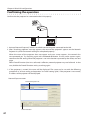
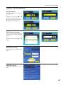
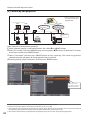
Confirming the operation
Confirm that the projector has connected to the LAN properly.
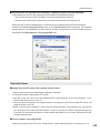
1. Activate “Network Capture 5” which is installed into the computer connected to the LAN .
2. After “Searching projector” message appears, the name of the projector* appears on the Network
Projector List, then the network setting has completed properly.
When the name of the projector does not appear and error screen appears, the network has
not connected yet. Try searching again with the Search PJ button. If error screen appears again,
reconfirm the LAN setting. When the projector is set in the location separated by the router, see next
page.
When Firewall function (Anti-virus software) is effective, network projector may not be found. In that
case, disable the Firewall function and try searching again.
✳ If the projector is named, the name will be displayed. The name can be set with the following
procedures in “6. Basic setting and operation” ➔ “Initial setting” (p50) . If the projector is not named,
IP address of the projector will be displayed.
Network Capture screen
Network Projector List
Search PJ button
30
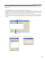
Confirming the operation
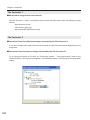
When set up the projector in the location separated by the router and the segment is different;
Projector will not be found nor displayed. In that case, the projector needs to be searched directly by
the IP address.
1. Press Specify IP button. "Search specified IP address" window appears.
2. Click Add button, "IP address set up" window appears. Enter the IP address of the projector and Click
OK button. Then, the projector will be added on the "Search specified IP address" window. Multiple
projectors are registered and they are stored even when the application is closed.
3. Click OK button on the "Search specified IP address" window, the registered multiple projectors
will be searched. Then, the projector will be added on the Network Projector List of the application
window.
Network Projector list
Specify IP button
"Search specified IP address" window
"IP address set up" window
31
Chapter 4 Wired LAN configurations
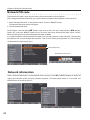
Network PIN code
The Network PIN code is to restrict the access from the networks to the projector.
After setting the Network PIN code, you need to enter it to operate the projector via the networks.
1. Select "Network PIN code" in the Network menu, and press SELECT button.
The Network PIN code screen will appear.
2. Set the Network PIN code.
Set the figures with the Point ed buttons and move to the next items with the Point 7 8 buttons.
Select “Set” and press SELECT button to set. To cancel the preset Network PIN code, select “Cancel”.
When you do not want to set the Network PIN code, set 0000.
It is recommended to set the Network PIN code if you use the projector via the networks. The Network
PIN code can be set also through the networks. See “6. Basic setting and operation” ➔ “Initial setting”
➔ “Network PIN code setting” (p51).
Network PIN code
Network PIN code screen
Network information
Select "Network information" in the Network menu and press Point 8 or SELECT button to show LAN
setting environment of the currently selected projector. (The description below is an example and
different from what will be shown.)
32
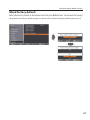
Wired LAN factory default settings
Wired factory default
Select “Wired factory default” in the Network menu and press SELECT button. All the wired LAN settings
will go back to the factory default settings. For details, refer to “Wired LAN factory default settings” (p.34).
33
Chapter 4 Wired LAN configurations
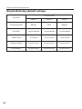
Wired LAN factory default settings
SELECTED LAN
Parameter
34
Wired 1
Wired 2
Wired 3
IP CONFIGURATION
MANUAL
DHCP
MANUAL
IP ADDRESS
169.254.100.100
192.168.100.100
192.168.100.100
SUBNET MASK
255.255.0.0
255.255.255.0
255.255.255.0
GATEWAY ADDRESS
255.255.255.255
255.255.255.255
255.255.255.255
DNS ADDRESS
255.255.255.255
255.255.255.255
255.255.255.255
Chapter
5
5. Wireless LAN configurations
This chapter describes the preparation for Wireless
LAN setting with projectors and how to set the LAN
environment.
This projector contains the Wireless LAN module.
The setting procedures and configurations differ
depending on the LAN installation location. Consult
your system administrator for installation and set the
LAN appropriately.
To operate via Wireless LAN, your computer has to
be equipped with a Wireless LAN card adapter which
supports IEEE 802.11b/g/n(DRAFT 2.0).
If connecting in Infrastructure mode with an access
point, the access point is required to support IEEE
802.11b/g/n(DRAFT 2.0).
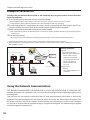
Caution: Do not use a mobile phone or PHS near
(within 20cm/8inch) the projector. It may
cause malfunction.
35
Chapter 5 Wireless LAN configurations
Setting the network environment
The projector contains the Wireless LAN adapter.
Set the Wireless LAN network through the projector menu.
Detailed network settings will be made with browser. Refer to “6. Basic setting and operation”. ➔ "Network
configuration" (p.53). Complete the settings described in this chapter before performing the steps in “6.
Basic setting and operation.”
Setting procedures
1. Turn on the projector and select “Network” in the Input menu of the projector.
2. Select “LAN mode select” in the Network menu, and press Point 8 or SELECT button.
3. S elect similar LAN environment among Wireless 4, Wireless 5 and Wireless Simple* with the Point
ed buttons. Then the Menu will disappear, the “Please wait...” message will appear, and switching
operation will start. Switching will take a while and after completing the operation, the “Ready for
use” message will appear.
For each settings, refer to "Wireless LAN factory default settings" on page 44.
✳ “SIMPLE” mode is used for simple setting without complicated LAN setting procedures to connect to
the Wireless LAN. See “Easy wireless setting” (p.41) for details.
36
4. Select "Network setting" in the Network menu and press SELECT button, and then the LAN setting
screen will appear and the selected LAN settings will be displayed. Adjust each item to the setting
environment. Consult your system administrator for the detailed settings.
Move among the items with the Point ed buttons and press SELECT button, move among the
columns with Point 7 8 buttons, adjust the figures with Point ed buttons, and then press SELECT
button to set.
When the network type is “AdHoc”, you do not have to change “Sub net” and “Gateway” and leave
them as default settings.
SSID/ESSID for the network type “Infrastructure” and “AdHoc” are required to be entered the same
characters into the projector, the access point, and the Wireless LAN compatible computer (up to 32
characters). Characters can be selected from A~Z, a~z, blank (space), 0–9, or - (hyphen) with the Point
ed buttons. Move to the next character with the Point 7 8 buttons.
You can confirm that the projector settings from “Network Information” in the projector menu (p.42)
Setting the network environment
5. After completing all the settings, select “Set” and press SELECT button. Now, all procedures have
been done. To cancel the adjusted settings, select the "Cancel" and press SELECT button.
To confirm whether the settings are correct, follow the procedures in “4. Wired LAN configurations”
➔ “Confirming the Operation” (p.30).
Network setting
DHCP: On
DHCP: Off
For configuring of WEP, WPA-PSK, WPA2-PSK security, select “Next”. Refer to “Configuring security
with the projector” on next page for details.
Item
Description
DHCP...........................Sets DHCP function On or Off. When you setup the network setting manually, select "Off". When
its set On, IP address, Subnet, Gateway and DNS are automatically set according to your network
environment *1.
IP address..................Sets IP address of the projector
Subnet........................Sets Subnet mask. Normally sets 255.255.255.0
Gateway*2. ................Sets IP address of the default gateway (Router)
DNS*3..........................Sets IP address of the DNS server. Must be set when the E-mail function is used.
Network type...........Sets Infrastructure or AdHoc mode. When the "AdHoc" is selected, the security "WPA-PSK" and
"WPA2-PSK" are not available.
SSID/ESSID....................Identifier of the wireless access point.
*1 Set "On" only when the DHCP server is available on your network environment.
*2 Set [255.255.255.255] if the network does not provide the gateway (router).
*3 Set [255.255.255.255] if you do not use the function E-mail alert.
* While the network communication function (p.96) or moderator function (p.105) is to be executing, the menus
"Network capture", "Network viewer" and "Memory viewer" are displayed in gray.
37
Chapter 5 Wireless LAN configurations
Configuring security with the projector
Configure security with the projector by following the steps below.
After configuring the network in “5. Wireless LAN Configurations” (p.35-44), select “Next” in the LAN
setting screen and press SELECT button. The security configuration screen appears. Refer to “6. Basic
setting and operation” ➔ “Configuring wireless LAN setting and security setting” (p.55) as well.
WEP configuration screen
Use the Point ed buttons to select the security type. To disable the security, select “Disable.”
Use the Point ed buttons to move among the items and adjust setting; use the Point 7 8 buttons to
move among the character positions of the key entry fields.
This projector provides the following security options. Use optimum security option on your network
environment.
WEP64(40)bit Open
WEP64(40)bit Share
WEP128(104)bit Open
WEP128(104)bit Share
WPA-PSK(TKIP)
WPA2-PSK(AES)
Notes when entering characters:
The “¥” symbol is displayed as “\” when the ASCII key is used. The “]” symbol is treated as a character
by the ASCII key, but it is not interpreted as a character by the HEX key. In HEX, the “]” symbol is
displayed in red and setting is denied.
You can not set all the characters with the “]” symbol. This will be considered as no operation.
ASCII key characters : Space - 0 to 9 A to Z a to z ! " # $ % & ' ( ) * + , . / : ; < = > ? @ [ ¥ ] ^ _ ` { | } ~
HEX key characters : 0 to 9 a to f
38
Configuring security with the projector
Use of security type "WEP"
1. Use the Point ed buttons to select "WEP" security type.
2. Select “Key index”. Use the Point ed buttons to choose the HEX or ASCII key. The four (#1–#4) kinds
of WEP keys can be configured. Use the Point 7 8 buttons to move to the right frame; use the Point
ed buttons to select a WEP key number (#1–#4).
WEP configuration screen
Refer the table below for the usable number of characters at the WEP security option.
WEP option
Characters
WEP64(40)bit ASCII
WEP64(40)bit HEX
WEP128(104)bit ASCII
WEP128(104)bit HEX
5 characters
10 characters
13 characters
26 characters
3. Use the Point ed buttons to select the Type field of the WEP key number that corresponds to the
one you selected above and press SELECT button. The WEP key entry screen appears. In the WEP key
entry field, all characters are displayed in “]”. Use the Point ed buttons to select a character; use the
Point 7 8 buttons to select a character position. Enter all the characters displayed with “]”.
When you select HEX at WEP key index and the entry key contains “]”, the “]” symbol is displayed in
red and setting is denied.
4. Use the Point ed buttons to select “Set” and press SELECT button to return to the Wireless setting
screen. Select “Set” in the Wireless setting screen to complete the network setting.
39
Chapter 5 Wireless LAN configurations
Use of security type "WPA-PSK", "WPA2-PSK"
1. Use the Point ed buttons to select "WPA-PSK" security type.
WPA-PSK(TKIP)
configuration screen
2. Use the Point ed buttons to select the key field and press SELECT button. The PSK key entry screen
appears. Enter the PSK key by using the Point buttons. If the input PSK key has an error, the PSK key is
indicated in red.
3. Use the Point ed buttons to select “Set” and press SELECT button to complete the network
configuration, and return to the "Network setting" in the Network menu.
Available PSK key characters
ASCII code.......8 to 63 digits
Hex code..........64 digits
* Security "WPA-PSK" and "WPA2-PSK" modes are not available when the "AdHoc" network type is selected.
* When you set the PSK keys with 64 digits, the projector checks whether all of the entered PSK keys are in Hex code or
not. If any of the ASCII code is included in the entered PSK keys, the entered PSK keys are indicated in red as error.
40
Easy wireless setting
Easy wireless setting
With this setting, you do not need any complicated LAN setting procedures.
The network type will be AdHoc mode.
CAUTION: This function can be used only when logged in by Administrative right with
Windows XP and Windows Vista, and cannot be used with Windows 2000.
Windows XP should be Service Pack 1 or later version.
Setting Procedures
1. Turn on the projector and select “Network” in the Input menu of the projector.
2. Select “LAN mode select” in the Network menu, and press SELECT button.
3. Select “Wireless Simple” with the Point ed buttons. Press SELECT button then the “Please wait...”
message will appear and switching operation will start. Switching will take a while and after
completing the operation the message “Ready for use” will appear. During the switching period, the
projector cannot be operated. (“SIMPLE” LAN settings will be shown by pressing SELECT button. The
settings cannot be changed.)
4. Activate “Network Capture 5” which is installed in the computer.
5. Click Wireless easy setting button on the operation screen. The Wireless LAN setting screen will
appear and the computer will start to set up the Wireless LAN setting. (Adjust the computer’s
Wireless LAN environment to the “SIMPLE” setting LAN environment.)
After completing the settings, the computer will start searching the projector which was set as
“SIMPLE” and will display the name of the projector or the IP address on the projector list.
Confirm whether the LAN has been set correctly and works properly. Refer to “4. Wired LAN
configurations” ➔ “Confirming the operation” (p.30) for the confirmation procedures.
If the network setup is not succeeded, the error screen will appear.
Setting screen
Error Screen
Wireless easy setting button
41
Chapter 5 Wireless LAN configurations
Computer environment and Wireless LAN connection;
Wireless LAN with Wireless Easy setting connection will be made via AdHoc mode. For setting contents,
refer to “Wireless LAN factory default settings” (p.44).
With the Easy setting, computer’s LAN environment setting will be switched to the setup environment.
Because of that, the LAN cannot work for the other operation while using “Network Capture 5”.
After terminating the application or pressing the Wireless Easy Setting button, the LAN environment
will automatically go back to the previous state.
Network PIN code
The Network PIN code is to restrict the access from the networks to the projector.
After setting the Network PIN code, you need to enter it to operate the projector via the networks.
Select “Network PIN code” from the projector menu and press SELECT button. Set with the same
procedures as setting Wired LAN Network PIN code. Refer to “4. Wired LAN Configurations” ➔ “Network
PIN code” (p.32).
Network information
Display the current LAN connecting environment. Select “Network Information” from the projector
menu and press SELECT button.
Wireless Information (Example)
Wireless factory default
Select “Network factory default” in the Network menu (p.33) and press SELECT button. All the wireless
LAN settings will go back to the factory default settings. For details, refer to “Wireless LAN factory
default settings” (p.44).
42
WIRELESS indicator display
WIRELESS indicator display
When the wireless LAN configuration is set up correctly and the wireless communication is established
with the access-point or computer in the network, the WIRELESS indicator on the front panel lights up.
When sending or receiving of data, it blinks.
Even though the wireless LAN in the network menu is selected, the WIRELESS indicator does not light,
in this case, the wireless LAN configuration is not set up correctly, and please check the setting of the
projector.
WIRELESS indicator
43
Chapter
5 Wireless LAN configurations
Easy wireless setting
Wireless LAN factory default settings
Factory default settings for Wireless 4, Wireless 5, and Wireless Simple as follows.
Selected LAN
Setting Items
44
Wireless 4
Wireless 5
Wireless Simple
IP CONFIGURATION
MANUAL
DHCP
MANUAL
IP ADDRESS
169.254.100.100
192.168.100.100
169.254. * . *
SUBNETMASK
255.255.0.0
255.255.255.0
255.255.0.0
GATEWAY ADDRESS
255.255.255.255
255.255.255.255
255.255.255.255
DNS ADDRESS
255.255.255.255
255.255.255.255
255.255.255.255
WIRELESS CHANNEL
11
11
11
NETWORK TYPE
802.11b AdHoc
INFRASTRUCTURE
802.11b AdHoc
WIRELESS SSID/ESSID
(SSID/ESSID)
PJ-WIRELESS5
ANY
PJ-WIRELESS5
WEP
(WEP encryption)
DISABLE
DISABLE
DISABLE
WPA-PSK
(PSK key)
DISABLE
DISABLE
DISABLE
WPA2-PSK
(PSK key)
DISABLE
DISABLE
DISABLE
Chapter
6
6. Basic setting and operation
Describes basic operation and settings below by using
the web browser.
• Initial setting
Setup the basic setting such as Projector name, Network
PIN code, Time setting, etc.
• Network setting
Configure Wired/Wireless LAN environment.
• E-mail Setting
Configure E-mail function to manage the projector.
• SNMP Setting
Configure SNMP function to manage the projector.
Caution: When operating the projector with the browser,
connect the projector to the computer with Wired or
Wireless LAN. Complete the connection in advance.
45
Chapter 6 Basic setting and operation
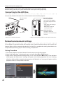
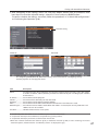
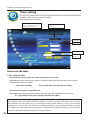
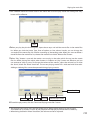
Starting up the Browser
1. Turn on the projector.
2. Start up the Network Capture 5. The Network Capture 5 searches projectors in the network and lists
up the IP address or projector name of the projector on the Network Projector List.
3. Double click the projector to set from the Network Projector List.
4. The web browser will start up and display the setting page of the projector.
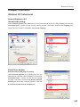
Select a display mode and login
T his product provides 2 types of control mode, Standard Mode and Light Mode as below. Select
a proper mode to match your PC and network environment by clicking on the text link. Once you
select your desired display mode, the setting page you selected display mode will be displayed
automatically from the next login. To change the display mode, click "Top" on lower-right corner of
the setting page (p.47).
STANDARD MODEFor computer display, displays graphical
m e n u s a n d s e t t i n g s. Th i s m o d e i s
recommended for standard use.
LIGHT MODEDisplays with 200 x 300 dots. This mode
is optimized for use of the handheld
computer, PDA, etc. It is also convenient
if the network traffic is heavy. (This mode
has some limitations on the network
viewer and multi-control functions.)
I f the password has been set on the setting page, the
authentication window will appear. In that case, type "user"
onto the User Name text area and the login Network PIN
code onto the Password text area and then click OK button.
* The entered User Name must be "user" and it can not be changed.
[Note]
When the projector is accessed for the first time or the Network PIN
code "0000" is set, the auto-login is performed and the next main setting page is displayed.
46
Starting up the browser
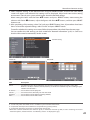
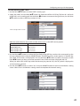
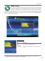
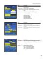
Display of main setting page
The following main setting page will be displayed depending on your display mode selection.
Perform various kinds of settings through this page. Click on the menus to display the control and
setting pages.
z Main setting page in the Standard Mode display
Clock display
Display on or off by
clicking text ON or OFF
Sub menu tab
Switches the sub
menu tab.
Page numbers
Switches the pages by
clicking the number's
tab.
Main menu
Setting page
For selection of control and
setting items of the projector.
Displays the control and
setting items according to the
selected menu.
R e t u r n s to D i s p l ay
Mode selection page
(☞ p.46)
* To change the screen language, use the initial setting menu (p.50)
✐T
his Standard mode display is mainly used through this manual for the setting and
control description.
✐I f your computer does not have the Adobe Flash
Player version 6 or later, follow the message on the
control page to install the Adobe Flash Player. For
further product information or installing, see the
Adobe homepage.
http://www.adobe.com
47
Chapter 6 Basic setting and operation
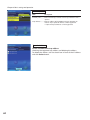
x Main setting page in the Light Mode display
Sub menu tab
Page numbers
Returns to the display mode selection
page.
Main menu
Setting page
Returns to main menu
✐ T he blank page appears if your PDA does not provide a Adobe Flash
Player. You need to install the Adobe Flash Player. (☞p.47)
The network viewer function in the Light mode has following limitations;
- Cannot select the program or folder for the display.
- Cannot check up the images in the folder or program.
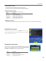
How to use the setting page
To control and set up the projector, use the setting menus on the web browser. The basic operation and
procedures commonly used on this manual are described below.
Example of the Setting Page
The setting pallet appears after clicking the item. Change the
value by clicking s or t button, or type the number onto the
text box directly and then click Set button.
* Each item has a valid setting range respectively.
Setting Pallet
48
✐ T he value in the text box indicates current value.
✐E ach item has a valid setting range. The setting value exceeding its range becomes invalid. Some control items can
not be used depending on the selected input mode or functions of the projector you use. In that case, the values of
those items are indicated with "---".
How to use the setting page
Type of the setting pallet
Text box setting
Enter the number or text and then
click Set button.
or
Change a value with s or t
button and then click Set button.
The value changes quickly when
s or t button is kept pressing.
Pull-down menu setting
Select an item with pull-down
menu button and then click Set
button.
or
Select an item by clicking s or t
button.
Radio button setting
Select an item by selecting a radio
button
Check box setting
Select items by ticking on check
boxes.
49
Chapter 6 Basic setting and operation
Initial setting
After installing the projector, perform the following basic initial setting.
Click Initial Setting on the main menu to display the initial setting page.
Item
Description
Language..................Switches display language on the setting page. English or
Japanese.
Model name.............Indicates the model name of the projector.
Projector name........Sets the name of projector. This projector name is listed on
the application window of the Network Capture software.
Network PIN code............Sets the Network PIN code to login the setting page (+p.32,
p.42)
PJLink..........................Switches PJLink password authentication on or off.
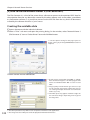
Password...................Password for PJLink function
50
Initial setting
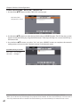
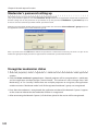
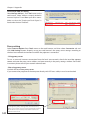
Network PIN code setting
This is to set the Network PIN code to restrict the access from an
unauthorized person through the network.
Enter a 4-digit number as the Network PIN code onto the text box and
click Set button.
The projector's network part begins restarting and it takes about 20
seconds. Close (Quit) the web browser and access to the login page
again in 20 seconds. This is to perform the login authentication firmly.
The default Network PIN code as [0000], which means no Network PIN code is set.
✐ When you connect the projector to the network, it is recommended to set a new Network PIN code. Only a fourdigit number is valid for the Network PIN code.
✐ If you forget the Network PIN code to the projector, you can check it by selecting "Network PIN code" sub menu
from "Network" menu on the projector. For further information, please see item "Network PIN code setting"
(+p.32, p.42).
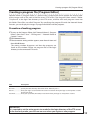
PJLink and password setting
This is to set the PJLink password authentication on or off. If "On" is set
with the PJLink pull-down menu, the password must be required. Enter
a password* onto the text box and click Set button.
Refer to the projector owner's manual for further details of the PJLink
function.
✐ 1 to 32 alphanumeric characters can be used for the password.
What's PJLink?
The projectors equipped with PJLink function can be used together on the same network, regardless
of model or brand, for centralized control and monitoring. This standard was established by the Japan
Business Machine and Information System Industries Association (JBMIA). http://pjlink.jbmia.or.jp/
51
Chapter 6 Basic setting and operation
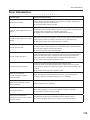
Item
Description
NTP address..............Enter the address of NTP server. Please consult your
network administrator for setting up of the NTP server.
Time zone..................Sets your country or region's time zone
Temperature.............Switches display temperature unit Centigrade or
Fahrenheit
Time setting..............When clicking AUTO button, the date and time set on
your computer are set to the projector. The timer icon
appears when time is set up correctly.
Current time.............Indicates current date and time set on the projector
Date.............................Sets date in manual
Time.............................Sets time in manual
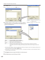
Date and time setting
NTP is abbreviated expressions of Network Time Protocol. It is a protocol to acquire the exact current
time via the network. This projector acquires the current time from the NTP server and update the time
in the network module. After setting the NTP address, the projector acquires the time per 24 hours. If
the projector fails acquiring the time from the NTP server, the projector tries to acquire the time every 1
hour until it succeeds.
✐ "Time zone" is the local time as an offset from Greenwich Mean Time (GMT). "Time zone" is in ± hour:minute
format and is available from -23:59 to +23:59.
ex. Time zone: +09:00 in Tokyo, Japan
✐ Both of "NTP address" and "Time zone" should be set, otherwise the setting will be failed.
When the NTP address is not set, perform the time setting with "Auto-setting" or "manual setting"
described below.
Auto setting
Click AUTO button on the page, the date and time set on your computer are set to the projector.
Note: C
onfirm that your computer has a correct clock time before performing the
auto time setting.
Manual setting
Click the item Date or Time and enter the date or time on the input box
with adequate format.
Date is in year/month/day format.
ex. 2007/10/05
Time is in 24-hour:minute format.
ex. 18:30
This projector does not provide the built-in battery. The date and time information are lost when
the projector turns off ( when "Eco" is set for the stand-by mode (Refer to p.74)), or the network
configuration is reset. The timer function is disable until time is set up correctly. When using the
NTP address for time setting, the current time is acquired at the projector starting up and the timer
function is activated after finishing the time setting correctly.
52
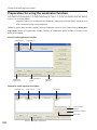
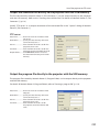
Network configuration
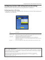
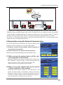
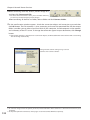
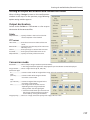
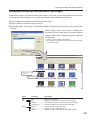
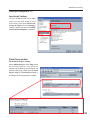
Network configuration
Click Network on the main menu. The following setting page is displayed. Set up the
projector's network environment on this Setting sub menu.
Setting of LAN
1. Select a type of LAN from Change setting pull down menu.
LAN1(Wired)
LAN2(Wired)
LAN3(Wired)
LAN4(Wireless)
LAN5(Wireless)
Simple(Wireless)
For the default setting of the above LAN, see the items "Factory Default Setting".
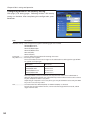
Item
Description
Change setting........Selects LAN1 to LAN5 and Simple
IP configuration......Sets DHCP or Manual
IP address..................Sets IP address of the projector
Subnet mask............Sets Subnet mask.
Default gateway*1...........Sets IP address of the default gateway (Router)
DNS*2..........................Sets IP address of the DNS server.
*1 Set [255.255.255.255] if the network does not provide the gateway (router).
*2 Set [255.255.255.255] if you do not use the function E-mail alert.
53
Chapter 6 Basic setting and operation
2. S elect either "Manual" or "DHCP" from IP configuration pull
down menu. When "DHCP" is selected, IP address, Subnet
mask, Default Gateway, DNS are automatically configured by
DHCP function. Only the DNS address allows you to set up
manually if the DNS address information is not provided on
your DHCP server. When selecting "Manual", configure all the
items manually. For further information, contact your network
administrator. The address must be entered as 4 number groups
separated by a dot like [192.168.001.101].
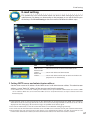
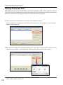
3. After completing the network configuration, press Set button to
register the network information. The Simple(Wireless) setting is
fixed, which cannot be changed from factory default value.
4. To apply the setting, press Set button. The network of the
projector starts re-booting and applies the setting. It takes about 20 seconds to complete. Close the
web browser and access to the login page again in 20 seconds.
On the screen of the projector, the “Please wait...” message will appear and switching operation will
start. Switching will take a while and after completing the operation, the “Ready for use” message will
appear. During the switching period, the projector cannot be operated.
When you use LAN4(Wireless) or LAN5(Wireless), the setting items of page [2] and [3] are activated
and you can setup Wireless LAN setting and Security setting. See the item " Configuring Wireless LAN
Setting and Security Setting" for further setting.
54
✐ When the IP address collides with the address of other equipment, the computer cannot communicate with the
projector. When the IP address collides with the address of other equipment, the computer cannot communicate
with the projector. Set an IP address again after selecting another LAN mode from "Change setting" or turning off
and then on the projector.
Configuring wireless LAN setting and security setting
Configuring wireless LAN setting and security setting
Configure the wireless LAN setting and security setting for Wireless 4 and Wireless 5.
Configuring wireless LAN setting
1. Click page [2] of setting pages. Following wireless LAN setting can be done. After completing the
configuration, press Set button.
Item
Description
Wireless Mode.........Select the Communication standard 802.11b or 802.11b/g/n.
Network Type...........Select either “Infrastructure” or “AdHoc”. When selecting the "AdHoc", the security
"WPA-PSK" and "WPA2-PSK" mode are not available.
SSID/ESSID................Set the SSID/ESSID. (up to ASCII 32 characters)
SSID/ESSID is case-sensitive. Even though all characters on the Wireless
information is uppercase, it is necessary to distinguish between upper case and
lower case characters.
Channel......................If you use the projector in 802.11AdHoc mode, select the channel, from 1 to 11.
Notes for entering characters:
The “¥” symbol is displayed as “\” when the ASCII key is used. The “]” symbol is treated as a character
by the ASCII key, but it is not interpreted as a character by the HEX key. In HEX, the “]” symbol is
displayed in red and setting is denied.
You can not set all the characters with the “]” symbol. It will be considered as no operation.
ASCII key characters : Space - 0 to 9 A to Z a to z ! " # $ % & ' ( ) * + , . / : ; < = > ? @ [ ¥ ] ^ _ ` { | } ~
HEX key characters : 0 to 9 a to f
55
Chapter 6 Basic setting and operation
Configuring wireless LAN security setting
lick page [3] of setting pages. Following wireless LAN security
C
setting can be done. After completing the configuration, press
Set button.
Item
Description
Network security....Sets the type of encryption. Following types are available.
WEP64(40)bit Open
WEP64(40)bit Share
WEP128(104)bit Open
WEP128(104)bit Share
WPA-PSK(TKIP)
WPA2-PSK(AES)
Input type.................ASCII or HEX. See item "Notes for entering characters"
Key index1 - 4..........Enter keys of encryption.
The used number of character changes as the table below according to the type of WEP
encryption and input type.
WEP option
Characters
WEP64(40)bit ASCII
WEP64(40)bit HEX
WEP128(104)bit ASCII
WEP128(104)bit HEX
5 characters
10 characters
13 characters
26 characters
Four key indexes can be set, however, the only one with check on its radio button is
effective. Both of the number and value of the key index in effect must be same as those
of your computer and the access point.
Depending on computers and access points, you may be allowed to select only one WEP
key. In that case, use key index1.
PSK...............................Available when the "WPA-PSK(TKIP)" or "WPA2-PSK(AES)" is selected.
The PSK key must be no fewer than 8, nor more than 63 digits with ASCII code, and 64
digits with Hex code.
56
E-mail setting
E-mail setting
This product has an E-mail function which can send an alert message to users or an
administrator if it detects an abnormality on the projector or run out of the life span
of the lamp. Click E-mail Setting on the main menu and follow the below steps.
Item
Description
SMTP server* . .........Sets server name or IP address of the SMTP server
Administrator
address.......................Sets E-mail address of administrator
Add e-mail
address.......................Sets E-mail address of the user to send a mail when the
projector has an abnormality.
1
1 Setting SMTP server and administrator address
Set the server name or IP address of the SMTP server*1 and administrator address. The administrator
address is set to "Reply-To" address of the message sent from the projector.
*1 The SMTP server is a server for sending E-mail. Please contact your network administrator to have this SMTP
server address. When the server name for SMTP server is used, DNS must be set up to activate the E-mail
function.(+p.53)
✐ I f the projector sends an alert message due to the abnormality on the projector but the SMTP server is down in
some other reason, the message will not be sent. In that case, the message "Unable to connect to server." will be
displayed on the setting page. To clear this message, set up SMTP server address again.
✐ To use the E-mail function, it must be set the DNS address on the Network setting page correctly.
✐ You cannot use this E-mail function if the DNS server and SMTP server cannot be used in your network environment.
✐ The projector does not send message to the address set in "Administrator address" text box. If you want to send
e-mails to the administrator address, enter the administrator address into "Add e-mail address" text box.
57
Chapter 6 Basic setting and operation
2 R egistering and deleting E-mail addresses
Click "Add E-mail address" and type the E-mail address onto the
text box and click Set button. To check the registered addresses,
click Check/Delete sub menu tab. The addresses are listed as the
figure on the right.
✐ Up to 10 E-mail addresses can be registered.
Check / Delete
To delete the registered addresses, check the address you want to
delete and click Delete button.
3O
ption selection for sending alert mail
Click Option sub menu tab. Check the condition items under
which alert mail will be sent and click Set button.
Please refer to the item "Examples :Type and contents of alert
mail" described on the next page.
Option
[1]––––––––––––––––––––––––––––––––––
o When PJ lamp is off.
o When PJ lamp replacement time is reached.
o When internal PJ power circuit is failed.
o When internal PJ temperature is too high.
o W hen PJ is turned into Standby in proper user
operation.
[2]––––––––––––––––––––––––––––––––––
o When accumulated filter use time reaches
[
] hours.
o W hen Power management function turns PJ
lamp off.
o When the signal is interrupted.
o When Auto Play is failed.
[3]––––––––––––––––––––––––––––––––––
o When lamp Corres. Value reaches
[ ] hours.
Attached message
58
✐ " When PJ lamp is off" signifies the lamp goes out
without user operation. "When PJ is turned into
Standby in proper user operation" signifies that the
projector is turned on by using the web browser
and then it is turned into standby with ON/STANDBY
button on the top control or the remote control.
✐ If condition "When Auto Play is failed" is checked, the
trap is sent when the error occurs during the auto
display operation using with the network viewer
function (+p.113). For further information of the
error, refer to item "Auto Display setting and control
page [3]"(+p.128).
✐T he length of message should be less than 255
characters.
✐ Up to 99,999 hours can be set for use time.
✐ The optional settings return to the factory default
when you unplug the AC power cord of the projector.
E-mail setting
Examples: Type and contents of alert mail
When the projector has an abnormality, the following alert messages are sent to the registered E-mail
address depending on your selected condition. Administrator or user can take an efficient action
quickly by receiving this message. This is very useful to maintain and service the projector.
The following are examples of received messages.
● When internal PJ temperature is too high:
TITLE: Message from projector
10-03-2007 00:59
Projector Model Name: model name
TCP/IP: 192.168.1.201 Projector Name: Proj05
It sends you following message.
*The Projector lamp is turned off, because internal Projector temperature is too high.
Wait for the completion of the cooling process and make sure the projector has been
turned into Standby. Then turn the projector on again.
If the Indicator continues flashing, check the air filter for dust accumulation.
[A] 81.5 degrees fahrenheit [B] 134 degrees fahrenheit [C] 95.6 degrees fahrenheit
Temperature of Sensor B is too high.
✐ The projector let users know the information which thermal sensors inside the projector detected the
abnormal temperature risen and so the projector was turned off. Please refer to item "Power control
and status check" (☞ p.66) for the location of the sensors and each temperature . Also see the owner's
manual of the projector for further details.
● When internal PJ power circuit is failed:
TITLE: Message from projector
10-03-2007 00:59
Projector Model Name: model name
TCP/IP: 192.168.1.201 Projector Name: Proj05
It sends you following message.
*The Projector lamp is turned off, because Projector power circuit is failed.
Unplug the Projector from AC outlet and ask servicing to qualified service personnel.
MAIN, P-FAIL OK
MAIN,
1.8V OK
MCI,
P-FAIL NG
Error information
✐ The projector detects the power failure. Unplug the AC power cord and plug it again, and then turn on the
projector to verify the operation. If the problem still persists, unplug the AC power cord and ask servicing to
a qualified service personnel.
59
Chapter 6 Basic setting and operation
● When PJ lamp replacement time is reached:
TITLE: Message from projector
10-03-2007 00:59
Projector Model Name: model name
TCP/IP: 192.168.1.201 Projector Name: Proj05
It sends you following message.
*The PJ lamp replace time is reached.
✐ Replace it with a new lamp immediately and reset the lamp counter. If the projector is used without
resetting the lamp counter, the alert mail is sent to users in every power-on of the projector. This
alert mail will not be sent when the mail sending condition "When the life span of lamp is reached" is
unchecked.
● When lamp corres. value reaches preselect use time:
TITLE: Message from projector
10-03-2007 00:59
Projector Model Name: model name
TCP/IP: 192.168.1.201 Projector Name: Proj05
It sends you following message.
*The accumulated lamp use time reaches 1800 hours.
Prepare for the lamp replacement.
Discretional messages
✐ T he projector sends a free message when the lamp use time (Corresponding value) reaches the
preselected lamp use time. It can be used for preparation of the lamp replacement and the maintenance
required.
60
SNMP setting
SNMP setting
This product provides a SNMP (Simple Network Management Protocol) agent
function. The SNMP consists of a manager and agents. The group which exchanges
information with SNMP is called "Community". There are two access modes in a
community, Refer (read only) and Set (read- write). This product allows to use Refer (read only) only. The
SNMP message informs the projector status called "Trap" to an administrator. Click SNMP Setting on
the main menu and set up each item.
PJ information
Item
Description
Contact......................Enter user name of the projector etc. (optional)
Place...........................Enter place of the projector (optional)
Community
name(refer)..............Enter community name (read only). Default name is
"public".
✐The SNMP agent provided with this product is based upon MIB-2 defined by RFC1213. For private MIB
information, refer to file "Mibinfo/XUPjNet.mib" in the CD-ROM.
61
Chapter 6 Basic setting and operation
Trap
Item
Description
Community name............Enter community name to send "Trap". Default name is
"public".
Trap address.............Enter IP address of the SNMP manager computer to
receive "Trap". Up to 10 address can be registered.
✐ Up to 10 trap addresses can be registered.
Trap check/delete
Check and delete the trap address
Checking the registered trap address and deleting the address.
To delete the address, tick the check box in front of the IP address
and click Delete button.
62
SNMP setting
Trap option
Trap option setting
Tick the check boxes in front of the condition item to send the trap.
✐ Click Set button if you tick or un-tick the check box on a page.
[1]––––––––––––––––––––––––––––––––––
o When PJ lamp is off.
o When PJ lamp replacement time is reached.
o When internal PJ power circuit is failed.
o When internal PJ temperature is too high.
[2]––––––––––––––––––––––––––––––––––
o W hen PJ is turned into Standby in proper user
operation.
o When accumulated filter use time
reaches [
] hours.
o W hen Power management function turns PJ
lamp off.
[3]––––––––––––––––––––––––––––––––––
o When the signal is interrupted.
o When Auto Play is failed.
o When lamp Corres. Value
reaches [
] hours.
✐ " When PJ lamp is off" signifies the lamp goes out without user operation. "When PJ is turned into Standby in proper user
operation" signifies that the projector is turned on by using the web browser and then it is turned into standby with ON/
STANDBY button on the top control or the remote control.
✐ Up to 99,999 hours can be set for the time setting.
✐ If condition "When Auto Play is failed" is checked, the trap is sent when the error occurs during the auto display
operation using with the network viewer function (+p.113). For further information of the error, refer to item "Auto
Display setting and control page [3]"((+p.127).
63
Chapter 6 Basic setting and operation
64
Chapter
7
7. Controlling the projector
Describes controlling and setting of the projector by
using the web browser.
65
Chapter 7 Controlling the projector
Power control and status check
Click Power & Status on the main menu. The control page will be displayed.
By clicking ON or Standby button on the page, the power of the projector can be
controlled.
Confirmation window as
shown in the below appears
when the Standby button is
pressed.
Popup confirmation window
Item
Description
PJ status
Power . ...........................Displays the status of the lamp. (ON, OFF, On starting up, On cooling down)
Status .............................Displays the status of the projector's power. (Refer to next page.)
Power control...............Controls the projector power by clicking the "ON" or "Standby" button.
PJ temp.
Inside temp.A ..............Displays the surrounding temperature of lamp in the projector.
Inside temp.B ..............Displays the surrounding temperature of panel in the projector.
External temp. . ...........Displays the surrounding temperature of the intake vent.
...........The warning icon will appear if the temperature exceeds a specified value. Check if there
is no object to obstruct the airflow around the intake or exhaust vent. It might be airfilter
clogged. Clean up the airfilter.
* The temperature unit can be set either Centigrade or Fahrenheit in the item "Initial
Setting". (+p.52)
66
✐ The projector cannot be turned on while the projector is cooling down.
✐ The web browser checks and updates the projector's condition every 30 seconds automatically.
Power control and status check
About projector condition
Status
Description
Normal...................................................................Projector is operating normally.
Power management in operation.......................Power management is operating
Lamp failure........................................................Lamp failure is occurring
Abnormal Temperature...................................The temperature of the projector became too high
Cooling down after abnormal Temp.Projector detects abnormal temp. and is cooling down itself.
Standby after Abnormal Temp.....................Projector detects abnormal temp. and is set into standby mode.
Power failure ......................................................Power failure has occurred inside the projector. Projector is turned off.
Unplug the AC cord and contact a qualified service personnel for service.
If the power failure occurs on the projector, "Power failure" is indicated on
the status column and the information icon appears on the power column
as shown below. Click this icon to display further information of the power
failure.
Click this icon to display
further information of the
power failure.
When a security (PIN code lock) has been set on the projector, you also cannot control it through
the network. To control the projector through the network, unlock the security on the projector
using with the projector's menu control.
Caution about turning on/off the projector via the networks
When turning on/off the projector via the networks, preset the projector as follows:
1. Select “Setting” from the Projector menu.
2. Select “Standby mode” from the Setting menu and set it as “Normal”.
If you set this function as Normal, the network part of the projector is constantly provided with
power even if the projector is turned off. If you set this as Eco, then the network part will be turned
off when you turn off the projector. Consequently, you cannot turn on/off the projector via the
networks.
67
Chapter 7 Controlling the projector
Controls
Click Control on the main menu. The setting method differs depending on the
contents of the page. Click on the page number to change pages and select desired
setting items.
✐ Please see the owner's manual of the projector to have the further information of each control item.
Input
This function is to select the input mode and source mode of the projector. Click Set button after
selecting the input and source mode.
Item
Description
Input............................Selects input mode of the projector.
Source.........................Selects signal source of the input.
Computer1 : RGB
Component
RGB(Scart)
Computer2 :
RGB(PC analog)
HDMI :
HDMI
Video :
Video
S-video :
S-video
Network :
Network
68
✐ The control page displays valid control items depending on the selected input mode, signal or functions of the
projector you use, therefore, there may be different controls between the described items and actual control items
on the page display. For further information , refer to the projector's owner's manual.
✐ When the projector is standby, only the timer on the setting menu is available; others are not available.
Controls
System
This function is to select the system of signal input to the projector. The available system mode are
listed on the pull-down menu button according to the input signal. Select a system and then click Set
button.
Available selection at the RGB(PC analog) input
Item
Description
XGA1...........................It automatically switches to the proper computer
system of the input signal.
* The computer system modes (VGA, SVGA, XGA.
SXGA, UXGA, WXGA...) which meet the input signal
listed.
Available selection at the Video/S-video/Scart input
Item
Description
AUTO...........................It automatically switches to the proper color system of
the input signal.
* The selectable color systems are PAL, SECAM, NTSC,
NTSC4.43, PAL-M and PAL-N.
* AUTO is fixed at the Scart input.
Available selection at HDMI input
Item
Description
D-480p........................It automatically switches to the proper scanning
system of the input signal.
* The selectable scanning systems are D-480i, D-575i,
D-480p, D-575p, D-720p, D-1080i and D-1080p.
D-XGA.........................It automatically switches to the proper computer
system of the input signal.
* The computer system modes (D-VGA, D-SVGA,
D-XGA. D-SXGA1...) which meet the input signal
listed.
Available selection at the Component input
Item
Description
AUTO...........................It automatically switches to the proper scanning
system of the input signal.
* The selectable scanning systems are 480i, 575i, 480p,
575p, 720p, 1035i and 1080i.
✐ I f the modes (Mode1 to Mode5) stored in the item "PC Adjustment" (☞ p.72) are available, they are also listed
together with the above mode.
69
Chapter 7 Controlling the projector
Image adjustment
This function is to adjust the projected picture image and save the image mode. To store the adjusted
value, click Store button, and to load the adjusted value, click Load button.
Item
Description
Contrast.....................Adjusts picture contrast
Brightness.................Adjusts picture brightness
Color............................Adjusts picture color saturation
Tint...............................Adjusts picture hue
Item
Description
Color temp................Sets a color temperature mode.
White balance
Red, Green,
Blue.......................Adjusts each white balance respectively.
Sharpness..................Adjusts picture sharpness.
* When the value of the white balance is changed, the color temp. indicates
"Adj."
Item
70
Description
Gamma......................... Adjusts brightness of darker part of the picture.
Noise reduction........Switches noise reduction mode
Progressive...................Switches progressive mode
Reset............................Resets the Image adjustment to previous levels.
Store............................Stores the Image adjustment values. Select an item
[Image 1 - Image 4] from the pull-down menu and click
Store button.
Load.............................Loads the Image mode.
Select an image mode from
the pull-down menu and
click Load button. There
may not be available mode
Input source
depending on the input
Image mode
Video Computer
mode as shown in the table
4
4
Dynamic
left.
Standard
4
4
Real
*
4
Cinema
4
*
Blackboard(Green)4
4
✐ The mark "4" indicates the available image mode in the selected input
Colorboard
4
4
source. The error message appears when the disabled image mode
Image 1 - 4 4
4
indicated with "*" is selected.
Controls
Sound
This function is to adjust the sound of the projector. The values in the text box represent the current
control value or status.
Item
Description
Volume.......................Adjusts the sound volume from the speakers.
Mute............................Suppresses the sound.
71
Chapter 7 Controlling the projector
PC adjustment
Click PC Adj. on the main menu. This function is to adjust the signal from the
computer connected to the projector to obtain the proper picture image on the
screen.
Item
Description
Current mode............Displays a current mode like VGA, SVGA, XGA, SXGA, UXGA,
WXGA, etc. or MODE1 - MODE5 are the customized mode
created by using the "Mode Store" function described below.
Auto PC adj...............Performs automatic adjustment.
Fine sync....................Performs Fine Sync adjustment.
Total dots...................Adjust the number of total dots in the horizontal period.
Clamp.........................Adjusts the phase of the clamp.
Display area
Horizontal................Adjusts the image area horizontally.
Vertical..................Adjusts the image area vertically.
Item
Description
Position
Horizontal............Adjusts the horizontal position of the screen.
Vertical..................Adjusts the vertical position of the screen.
Reset............................Resets the PC adjustments to the previous levels.
Mode Store...............Stores the PC adjustment values. Select a mode no.
[Mode1 - Mode5] from the pull-down menu.
Mode Free.................Clear the PC adjustment values. Select a mode no.
[Mode1 - Mode5] from the pull-down menu.
72
Setting up the projector
Setting up the projector
Click Setting on the main menu. This function is to set up the projector. Select the
sub menu [Screen setting], [Setting 1] or , [Setting 2] and then set up each setting.
Item
Description
Screen.........................Switches the screen mode. There may not be available
mode depending on the input mode as shown in the
table below.
Input source
Screen mode
Video
Computer
Normal
True
Full Zoom
Wide
Natural wide
Custom
4
*
4
4
4
4
4
4
4
4
*
*
*
4
✐ The mark "4" indicates the available screen mode in the selected input
source system. The error message appears when the disabled screen mode
indicated with "*" is selected.
73
Chapter 7 Controlling the projector
Item
Description
Language..................Sets the language display of projector's on-screen
display menu.
Auto setup................Executes the Auto PC Adj, and Input Search function
below according to the each setting after clicking Start
button.
Auto PC adj..........Sets Auto PC Adjustment mode.
Input search........Sets the auto-input signal detection mode.
Auto keystone....Sets Auto Keystone mode.
Background..............Sets the screen background when no signal input.
Item
Description
Display........................Switches on or off the on-screen menu display on the
screen.
Countdown off..... Displays image during the starting up.
Logo............................Sets the logo display on the screen during the startup.
Ceiling.........................Sets the image top/bottom and left/right reversed.
Rear..............................Sets the image left/right reversed.
HDMI setup...............Sets the input signal form of HDMI input.
Image.....................Sets the Digital R/G/B image level of HDMI.
Sound....................Sets the audio input when using HDMI.
Item
Description
Terminal.....................Sets the terminal of "COMPUTER IN 2/MONITOR OUT".
Pointer........................Sets the pointer form.
Picture in Picture.....Sets the Picture in Picture mode and set the sub picture
size and position.
Mode.......................Sets the Picture in Picture mode.
Subpicture size....Sets the sub picture size.
Subpicture position...Sets the sub picture position.
Item
74
Description
Power
management...........Sets into the selected power management mode if the
input signal is interrupted and no control key is pressed
for the specified period of time.
*The specified time can be set 1 to 30 min.
On start......................Sets the power-on mode when the AC cord is
connected to the outlet.
Standby mode.........Sets the network function enable or disable in the
standby mode.
Normal......Enable
Eco.............Disable
Lamp control............Selects the lamp control mode.
Remote control...........Sets the remote control code.
Setting up the projector
Item
Description
Key lock......................Sets the prohibition of controls either Projector or
Remote control.
Closed caption.........Sets the closed caption function.
Closed caption...Sets the closed caption mode. (OFF/CC1/CC2/CC3/
CC4)
Color......................Sets the color of the contents. (Color/White)
Fan...............................Sets the cooling options after turning off.
L1 Normal cooling
L2 Silent cooling
Fan control...............Sets the fan control speed.
Off Normal mode
On1 Highland mode 1
On2 Highland mode 2
On3 fan speed Max mode
Item
Description
Lamp Corres. value....Displays the use time (Corresponding value) of the
lamp and reset the counter.
Filter counter............Displays the filter use time. Reset the time after filter
clean-up.
Filter warning...........Sets the time to indicate the filter warning message
on the screen.
Item
Description
Factory default................. Sets all of the projector control items to the factory
default setting except the following items.
Lamp Corres. Value, PJ time, Filter time, PIN code lock
and Logo PIN code lock.
No show.....................Sets the black out image temporarily.
Freeze.........................Sets the image to freeze mode.
P-Timer.......................Switches the P-Timer display.
ON........... Starts P-Timer indication
STOP....... Stops P-Timer counting
OFF......... Stops P-Timer indication
75
Chapter 7 Controlling the projector
Timer setting
This page is to set the timer to turn the projector off or on at a programmed day/date
and time. Follow the steps below for setting.
Click Timer on the main menu.
"---" will appear on the current time when the time is
not set up correctly.
Present time set on the
projector
Select date
Select day
Set execute time
Event
action
How to set the timer
1 Set a day or date
To set the timer event at the same time everyday or every week,
Select day entry with radio button and then select desired day from the pull-down menu button.
The selectable days are as follows:
- Same time everyday
- Every week (days from Monday to Sunday)
To set the timer event on specified date,
select date entry with radio button and then type the date with (Year/Month/Date) format.
Ex.: Type [2007/12/20] if you specify [December 20, 2007].
This projector does not provide the built-in battery. The date and time information are lost when
the projector turns off (when "Eco" is set for the stand-by mode (Refer to p.74)), or the network
configuration is reset. The timer function is disable until time is set up correctly. When using the
NTP address for time setting, the current time is acquired at the projector starting up and the timer
function is activated after finishing the time setting correctly.
76
Timer setting
2 Set an execute time
Type the time with (Hour:Minute) and 24 hours format.
Ex.: Type [18:25] if you specify [PM 6 o’clock and 25 minutes].
3 Select an event action
Select an event action from the pull-down menu.
Event
Action
ON................................... Turns on the projector
OFF................................. Turns off the projector
Lamp Auto................... Changes lamp mode to "Auto"
Lamp High................... Changes lamp mode to "High"
Lamp Normal.............. Changes lamp mode to "Normal"
Lamp Eco...................... Changes lamp mode to "Eco"
4 Register an event
Click Set button to register the set timer event. Repeat steps 1 to 4 for another timer event setting.
Check the timer events
To check the set timer events, click Check button. The timer
events are listed. The event with blue background color represents the timer-OFF event.
Change the event mode
On the event list appearing by clicking Check button, click on the
event you want to delete, disable or enable. Click Cancel, Delete,
Timer ON or Timer OFF button on the popup pallet.
Button
Operation
Cancel.........................Cancels the setting
Delete.........................Deletes the timer event
Timer OFF..................Disable the timer event temporarily
Timer ON...................Enable the timer event
77
Chapter 7 Controlling the projector
Notes on timer setting
✐U
p to 10 timer events can be registered. Timer events always operate according to the next valid event depending
on the projector's power status. In the example below, event 3 turns on the projector so next event 4 (also turning
on projector) will not be effective because the projector is already turned on. Similarly, when the projector is
turned off by event 5, event 6 OFF will not be effective in turning it off again. But these secondary events (event 4
and event 6) will become effective if a person turns off the projector (after event 3 and before event 4) or turns on
the projector (after event 5 and before event 6).
Invalid event
Projector Power
Event 1
Event 2
Event 3
Event 4
Event 5
Event 6
ON
OFF
Invalid event
ON
OFF
OFF
ON
OFF
ON
ON
OFF
OFF
Time
✐ When the timer events are set at the same time, the last event set will override the previous events. For example,
if there is an event like "ON at 8:00 everyday" and then new event is set like "OFF at 8:00 everyday", only the last
setting event is effective.
✐ When the timer event ON occurs during cooling down period, this is invalid event because the projector cannot be
turned on during that cooling down period.
78
Projector information
Projector information
This page is to display the basic information of the projector status. Click
Information on the main menu.
Items
Description
Input............................Displays selected input and source.
System........................Displays selected signal system.
Signal..........................Input signal status
Screen.........................Displays screen mode.
Lamp status...............Displays lamp status with an animation. Refer to the
table on the next page.
Security......................Displays the security (PIN code lock) status
Click this button to
update the information
79
Chapter 7 Controlling the projector
Indication of the lamp status
Icon display/background
Status
White-Yellow/Blue
Lamp on (Normal)
White-Yellow/Red
Lamp on (Lamp is being used over a specified use time, replace lamp immediately)
Gray/Blue
Lamp off (Normal)
Gray/Red
Lamp off (Lamp is being used over a specified use time, replace lamp immediately)
Red/Blue with X
Lamp failure (Lamp failure, check the lamp condition)
Red/Red with X
Lamp failure (Lamp failure and lamp is being used over a specified use time, replace
the lamp immediately)
Items
Description
PJ time........................Displays the accumulated use time of the projector.
Lamp Corres.
Value...........................Displays the use time (Corresponding value) of the
lamp.
Filter time..................Displays the use time of the filter.
Timer...........................Displays the timer setting status.
ON Timer has been set.
OFF No timer setting.
80
Multi-control
Multi-control
Controlling and setting the multi-projectors
When you install multiple projectors in the network, you can control and set up them
together. Click Multi Control on the main menu to display the control page.
Note: To control the multiple projectors, each projector must be set the same Network PIN code.
Example of multi control
PJ1
PJ2
PJ3
PJ4
PC6
PC5
PC4
Select Input2 for
PJ1 to PJ4.
81
Chapter 7 Controlling the projector
Start/stop the multi control
To start or stop controlling the multi-projectors, click Multi
control setting menu and select ON or OFF.
Switches on and off the
multi-control function
Multi control setting
OFF...........Stops multi control function
ON.............Starts multi control function. The multi control
menu will appear when ON is set. These items of
menu are linked to the main menu.
The multi controllable menus are "Power & Status", "PC
adjustment", "Control", "Setting", "E-mail setting", "Timer", "SNMP
setting" and "Network Viewer". Click each menu and perform
setting and adjustment.
✐ The word "MULTI CONTROL" appears on the each control page while
the multi control is operating.
This shows the multi control is
operating now.
82
Multi-control
Register the projector
To use the multi control function, register the IP address of the projector you intend to control. Click Pj
registration sub menu tab and set the IP address, Memo and Multi control item, then click Set button.
Items
Description
IP address..................Enter IP address of the projector to control
Memo.........................Enter projector name or installed location etc.
Multi control item
Control.................. Controlling the projector
Control & Image......... Controlling and displaying images
Image.................... Displaying the images
Confirmation of registered projector
To check the registered information, click Check & Change sub menu tab. The registered information of
the projector is listed as the below.
* The word "none" is displayed if the "Memo" function is used.
* When you click on a listed IP address, the
login page for the selected projector will
be displayed with a new window.
IP address
Status
Memo
Page no.
Click here to close
the sub menu Check
& Change.
✐1
0 projectors can be registered per page and up to 100 sets can be registered for the multi-control.
83
Chapter 7 Controlling the projector
Change the mode of the registered projector
To change the mode of the registered projector, select a mode with the pull-down menu button under
the IP address of the target projector and then click Set button.
Mode
Operation
Control........................ Controlling the projector
Control & Image............... Controlling and displaying images
Image.......................... Displaying the images
OFF.............................. Excluding from the multi-control
Delete......................... Deleting from the multi-control
* T he multi control item is not changed during using the network
viewer function. It is not available with the light mode.
Status
I f s o m e o f t h e re gi s te re d p ro j e c to r s a re d i s a b l e d by
some reasons (such as disconnecting the power source,
disconnecting the LAN cable, disconnecting from the network),
control changes will continue to be effective for the projectors
that are still active. At the same time, the deactivated projectors
are excluded from the multi-control. The status of the registered
projectors are indicated under the projector name. See the
table below for status indications.
Status
Status
Description
(blank).........................The projector is connected to the network correctly
No connect...............The projector may not be connected to the network. Please check the connection and network
configuration of this projector.
PIN code error..................The PIN code is incorrect. The PIN code for the multi-controlled projectors must be the same.
Change the PIN code of this projector to the common PIN code. (p.32, p.42)
File Error..................... Not displaying the images. Check if this projector is using the Network Capture function or
Network Viewer function individually, or in the standby mode.
* The projector updates the status at the time when the multi-control function is executed.
84
✐ I f the multi-controlled projector is in the standby mode, items of "PC adj.", "Control" and "Setting" cannot be
operated.
✐C
annot register, delete or change the multi-control setting during using the network viewer function.
✐ I t is recommended that a specified projector should be chosen for setting as a master when you use this multicontrol function. The control for the multi-controlled projectors will become too complicated operation if this
function is used for each projector.
✐ I f the registered projector is not connected to the network, it will take a while to complete the multi-control
operation because of waiting for the response from each registered projector.
✐ There are some disabled items in the multi-control function for the light mode.
Multi-control
Check & Change page in the light mode
Following functions in the "Check & Change" page are not
available in the light mode.
- Changing the control mode.
- Deleting the registered IP address
- Indicating the each status
- Indicating the each memo
This indicates that the
mode is "Image".
Connection status
Blinking: Connected
Gray: Disconnected
This indicates that the
mode is "Control".
(Check & Change page in the light mode)
Controlling all together
"Power & Status", "PC adjustment", "Control" and "Setting" can
be controlled all together. Set "ON" the multi control setting and
adjust controls of each menu. The setting value is applied to the
registered projectors sequentially .
✐ This is effective only if the multi control item of the registered projector is
set to either "Control & Image" or "Control".
Setting all together
"E-mail setting", "SNMP setting" and "Timer" can be set all
together. Set "ON" the multi control setting and items of each
menu. The setting value is applied to the registered projectors
sequentially.
✐ This is effective only if the multi control item of the registered projector is
set to either "Control & Image" or "Control".
85
Chapter 7 Controlling the projector
Viewer auto setting all together
"Viewer auto display" can be set all together. Set "ON" the multi
control setting and select [3] Auto display from Viewer sub menu
(selected by ‘Multi-control’ - “Network Viewer” menu). Set the
display time periods and repeat times for the auto image display.
After clicking Start button, the registered projectors start playing
back the auto image display in sequential.
✐ F or further information of the Auto display, see "Using the network
viewer function". (+p.124)
✐ This is effective only if the multi control item of the registered projector is
set to either "Control & Image" or "Image".
86
Chapter
8
8. Network capture functions
Network Capture is a function to display the screen
image and reproduce the sound of the computer via
the network.
- Real Time Capture
- Network Communication
- Moderator Function
- Playing Movie files
87
Chapter 8 Network capture functions
About Network Capture function
The Network Capture is a function to display the screen image and reproduce the sound of the
computer which has a Network Capture 5 software by the projector through the network. This function
has 3 kinds of mode as below.
- Real Time Capture (+p.91)
A function to display the screen image and reproduce the sound of the computer by the projector
through the network in real time.
- Network Communication (+p.96)
This mode is to communicate by sharing the capture image of a computer with multiple computers
and a projector. User can draw the text and figure on the captured image by using a drawing tool.
- Moderator Function (+p.107)
The moderator can project the participants’ computer screen through the projector in meetings or
in classes.
✐ Up
to 30 computers can be registered.
✐ The Network Capture function cannot be used when the Network Viewer function is used. The Real Time Capture,
Network Communication, Moderator function and Memory Viewer function cannot be used at the same time.
Start up the Network Capture 5
To start up the Network Capture 5, click "Network Capture 5" from "Start" - "All Programs" - "Network
Viewer & Capture 5" menu. The application window will appear and search the projectors in the
network and list them on the projector list.
If any projector is not listed, check followings and then search again by pressing PJ Search button.
- Is the projector turning on and connected to the network?
- Is the network setting of projector and computer configuring correct?
- Is the same capture port no. used among computer and projectors?
88
About Network Capture function
Commands on the task bar
When the Network Viewer & Capture 5 icon on the task bar is clicked, the popup menu will appear. It
provides according to the operating modes as shown in the table below.
Network Capture activating
Parameter set up...
Window show..
Version information..
Shut down
Menu during Playing movie files
Menu during Real time capturing
One-shot executing
Real time capture executing
Start real time capture
One-shot capture
Terminate capture
Window show..
Version information..
Shut down
One-shot capture
Terminate capture
Window show..
Version information..
Shut down
Playing movie files
Terminate Play movie files
Window show..
Version information..
Shut down
Menu during Network Communication
Communication executing (Main PC)
Communication executing (Sub PC)
Start editing
Terminate Communication
Capture transfer
End editing
Version information..
Shut down
Version information..
Shut down
Version information..
Shut down
Menu during Moderator function
One-shot executing
Real time capture executing
Start real time capture
One-shot capture
Terminate capture
Window show..
Version information..
Shut down
Items
Communication executing (Sub PC)
Capture transfer
Terminate Communication
One-shot capture
Terminate capture
Window show..
Version information..
Shut down
Joining in Moderator's group
(client PC)
Leave moderator's group
Version information..
Shut down
Description
Start real time / Terminate capture....... Starts / Terminates the real time capturing. (+p.91) The screen image of the computer
is projected on the screen in real time.
One-shot capture................................ Transfers the one-shot screen image of the computer.
Capture transfer.................................. Transfers the screen image of the computer to the projector. The captured image edit
window appears on the computer screen.
Select capture object*........................... Sets to display the capture window selection dialog.
* This menu will appear when "Select capturing object" is checked on the parameter
setting. (p.90)
Terminate communication................... Terminates the network communication.
Start editing....................................... Acquires the screen image in the network communication and displays it on the
editing window on the computer.
Terminate editing............................... Terminates the editing window of the network communication.
Terminate Play movie files................... Terminate the Play movie files.
Parameter set up................................ Sets the communication parameter between the computer and projector. For further
information, see item "Parameter set up" on the next page.
Window show.................................... Displays the application window on the screen.
Version information............................ Displays the version of this software.
Shut down......................................... Quits the Network Capture 5 application.
89
Chapter 8 Network capture functions
Parameter set up
Click Parameter set up button and setup the parameters on the Parameter setup window.
Items
Description
Connection setting
Capture port................ Sets the capture port no. on the projector. Default is 9000.
Pincode.......................... Sets the Network PIN code on the projector.
PJ search time.............. Sets the time to search the projector between 1 to 60 seconds. Default is 5 seconds.
q Search PJ when starting up Network capture
Check if Search PJ automatically starts when launching the network capture function.
q Select normal network adapter Uses default setting. Default is un-checked.
q Auto-power on....... The projector turns on and projects the computer's captured image on the screen
automatically when the network capture is executed while the projector is in the standby.
Image setting
Display adapter........... Provided for the use of a computer with
multiple network adaptors installed.
Select a network adaptor which has
the computer's screen to project with
the projector and execute the network
capture function. This is useful function
when you make the presentation.
Select capturing object..... Check if you want to select an
individual window on the computer
screen. This is useful function when
you open the multiple windows on the
computer's screen. When you execute
the capturing, the window selection
dialog appears. Select a window name
from the dialog window. The projected
window size is automatically adjusted
to fit the projector's screen size.
Sharpness..................... Select a capturing picture quality
among "High, "Medium", "Low"
q Reduce image......... Check if the capturing image resolution
is more than projector's panel
resolution (WXGA),
q Layer window capture..Check if layer window image capturing.
Capture start up time....... Sets the delayed time from the capture
start in second.
Moderator function setting
Nickname...................... Sets moderator's nick name
Moderator login password... Sets Moderator's password
Play Movie files setting
Repeat times................ Sets repeat times of the playing movie files. If set to “0”, loop play the movie file lists endlessly.
90
✐ To check the Capture Port number, see item "Control by the web browser" (☞ p.93). To check the PIN code, see item
"Network PIN code setting" (☞ p.32, p.42).
✐ S pecify the port number of TCP/IP. The default port setting is 9000. There are some reserved port numbers and also
some applications may use their own port numbers. If one of those port numbers is used, the alert dialog window
will appear and let you know that it is an invalid port number. In that case, use another port number.
✐ The reserved port numbers are http (80), ftp (21), telnet (23), (25), (110), etc. The port no. 4352, 10000, 10001 are
reserved to control the projector through the LAN port.
Using the Real Time Capture
Using the Real Time Capture
This is a function to project the screen image and reproduce the sound of the computer by the
projector in real time. The captured image projected by the projector can be selected from the
computer, web browser and the projector respectively.
Registering the computers
Up to 30 computers can be registered.
1 Access to the control page of the projector by using the web
browser. From the Network menu, click Capture tab to display
the setting page.
2 Switch to Connection Setting page by clicking the page
number tab [3]. Enter the IP address of the computer to the PC
number, and then click Set button. Click Set button to register
the IP address for each page.
✐ When you capture the screen image of the movie player software with the real time capture function, the projector
may not be able to reproduce the sound. To reproduce the sound in the projector correctly, follow the procedures
below;
• Start up the Network Capture 5 software first, start up the real time capture and then start up the movie player
software.
• Terminate the movie player software first and then terminate the real time capture.
✐ The registered computer enables to start capturing if only the Network Capture 5 is activated.
✐ The transfer speed of the captured image using the Real Time Capture function is depending on the network
environment and data volume of the image. It cannot be supported for movie pictures.
✐ I f you start capturing with the Select capturing object on the parameter set up window checked, the Select
capturing object window below (right side)
appears. Select the desired window title from
the window list and click OK button.
If no window is opened, no window title is
displayed on the window list as shown on the
left figure. Even the new window is opened,
the display of the Select capturing object
window would not change. If you would like
to capture the new window opened, click
Update button to show the window title on
the window list, select it and click OK button.
91
Chapter 8 Network capture functions
[1] Control by the computer
* PC provides the Network Capture.
PC1
PJ2
PJ1
Project
this screen
PC2
PC2
image with PJ2.
Capture
PC3
PC4
PC6
PC5
* Start capturing from the
PC1.
Select input mode to "Network" previously.
1 Start up Network Capture 5.
2 Select the projector(s) listed on the projector list on the application window and click Start real time
capture. The application window will disappear and then the screen image of the computer will
appear on the projected screen in real time.
* You can select multiple projectors (up to 5) on the projector list.
• To stop capturing, click One-shot capture on the popup menu appearing by clicking on the Network
Capture 5 icon on the task bar. The captured image of the computer on the screen is frozen.
• To restart capturing, click Start real time capture on the popup menu.
3 To end capturing, click Terminate capture on the popup menu appeared by clicking on the Network
Capture 5 icon on the task bar.
One-shot capture
Terminate Capture
Window show..
Version information..
Shut down
92
✐ I f the error message appears, check the item "Parameter set up" (+ p.90).
✐ The sound output from the projector can be controlled with the volume slider and mute item on the application
window of the Network Capture 5 software (+ p.25-26, p.90).
Using the real time capture
[2] Control by the web browser
* PC provides the Network Capture.
PC1
PJ2
PJ1
PC2
Capture
PC3
PC4
PC6
PC5
Project a screen
image of PC1 with
PJ2.
* S tar t capturing of
t h e P C1 f r o m t h e
PC5.
Select "Network" as input mode previously.
1 Access to the control page of the projector by using the web
browser. From the Network menu, click Capture tab to display
the setting page.
2 Select the computer number from the pull-down menu button
of "Connecting PC" and click Start button. The screen image of
the selected computer will appear on the projected screen in
real time.
• To stop capturing, click One-shot button. The captured image
of the computer on the screen is frozen.
• To restart capturing, click Start button.
3 To end capturing, click End button.
Set "On" when
using the wireless
mouse function
Item
Description
Interrupt connection................Set enable or disable the real time capturing
connection from other computers during executing
the real time capturing operation.
✐ The IP address of the connecting PC should be registered previously (☞ p.91).
✐ If the error message appears, check item "Parameter set up" (+ p.90).
✐ To use the capture function from the web browser or projector, the Network Capture 5 on the captured computer
must be activated.
93
Chapter 8 Network capture functions
[3] Control by the projector
* S tar t captur ing of
the PC1 from the
projector PJ2.
* PC provides the Network Capture.
PC1
PJ2
PJ1
PC2
Capture
PC3
PC4
PC6
PC5
Project a screen
image of PC1 with
PJ2.
Select "Network" in the Input menu previously.
1 Select "Network capture" in the Network menu. Press Point 8 or SELECT button.
2 Select "PC number" and press SELECT button and using Point ed buttons to select the PC number
to connect, and then press SELECT button.
3 Select "Connected" and then press SELECT button to start capturing. The screen image of the
selected computer will appear on the projected screen in real time.
4 To end capturing, select "Disconnect" and then press SELECT button.
Set "On" when
using the wireless
mouse function
94
✐ The IP address of the connecting PC should be registered previously (☞ p.91).
✐ If the error message appears, check item "Parameter set up" (+ p.90).
✐The projector does not provide the function to register the IP address of the computer and to set the parameter of
the capturing. They should be registered by using the web browser previously (☞ p.91).
✐The remote control which is provided with the projector does not have the mouse operating function.
Using the real time capture
[4] Control by the computer with USB memory
PC1
* S tart capturing of
the PC1.
Project
PC2this screen
image with PJ1.
PJ1
*USB memory provides
Auto Capture program.
The real time capture function can run automatically on the computer without the Network Viewer
& Capture 5 software installed by executing the Auto Capture program in the USB thumb drive
connected to the computer. The USB thumb drive for Auto Capture is supplied with this projector.
1. Turn on the projector and select “Network” from the Input menu of the projector.
2. Select “LAN mode select” from the "Network" menu of the projector and press SELECT button. Select
"Wired 1/2/3" or “Wireless Simple” with the Point ed buttons. (☞ p.41)
3. By connecting the above USB thumb drive, the removable disk window appears. Select "[Network
Capture 5] Open Program using the program provided on the device." and then click OK.
4. Automatically, the activated executable file configures the Easy wireless setting. (If the network
adaptor selecting window appears, select an option according to your network environment.) Then,
it searches the projector, and starts the real time capture of the computer screen.
5. If the auto-run program does not start automatically, double-click "WinAutoCap5" in the USB thumb
drive. (The auto-run program works only with Windows XP and Windows Vista.)
*The connection process of AutoCapture is different according to the equipped LAN adapter..
In case of only the wired LAN adapter is provided in the computer:
Connect to the network with the wired LAN adapter and search a projector.
In case of only the wireless LAN adapter is provided in the computer:
C
hange the LAN setting of the computer to SIMPLE and search a projector with the wireless LAN adapter.
In case of both the wired and wireless LAN adapters are provided in the computer:
W
hen "Usually set it to a network adapter to use" is not checked; the network selection window is displayed.
6. For the following operations, refer to Page 92.
Setting condition for automatically starting the real time capture function
Projector: Computer PC1:
Power: On, Input mode: Network, LAN mode select: Wired 1/2/3 or Wireless Simple
The searching result becomes only one projector.
Log in by Administrative
The wireless LAN card or the wired LAN card: Provided, Network Capture 5 software: N
IL
Activate WinAutoCap5 in USB thumb drive
✐ I f the error message appears, check item "Parameter set up" (+ p.90).
✐ When your computer provides multiple network adaptors, and "Select normal network adaptor" on the parameter
setup window is un-checked, the network adaptor selecting window (+ p.26) will appear.
✐ When plural projectors are found, the real-time capture will not start, but will become standby status. Release the
wireless LAN SIMPLE setting of the projector which is not for the real-time capture.
✐ When the software of Network Capture 5 is not installed in the computer, the sound data is not transferred. If you
want to transfer the sound data, install the software beforehand.
✐ I f the specified files are copied in the root of commercial USB memory, you can also perform the AutoCapture.
95
Chapter 8 Network capture functions
Example of advanced use
Displays the presentation data stored in the computer by using the wireless mouse function
from the projector.
1 Start capturing of the computer PC1 by using the projector.
S elect “Network Capture” icon from the menu and select "PC1" and then select "Connect" (☞ p.94).
=> The Network Capture software installed in the selected computer will start capturing.
2 On the image of the PC1 projected on the screen, search a presentation file data stored in the PC1 by
using the wireless mouse function of the remote control supplied with the projector.
3 Select a desired file and double click with the remote control .
=> The application by which the document was created starts and the projector projects the presentation picture
on the screen.
4 Start the presentation.
=> By using wireless mouse function, control the page browsing and some other operations for the PC1.
✐ F or further instructions of the wireless mouse, please refer to the projector’s owners manual.
✐O
n the projected screen using with the network capture, the shape of the mouse pointer differs from the one on
the computer’s screen.
Setting condition
* PC provides the Network Capture.
PC1
PJ2
PC2
Project a screen
image of PC1
with PJ2.
Capture
PC3
PC4
PC5
* Controls PC1 with wireless mouse.
Projector
Input mode: Network
Registering the connection: The IP address of the
computer and proper
parameter must be set to
the PC1 (☞ p.90-91).
Mouse Display: "On"
(☞ p.93)
Computer PC1
Software: The Network Capture 5 is
activated.
Using the Network Communication
This Network Communication is to communicate by sharing the captured image of a computer with
multiple computers and a projector. Users can draw the text and figure on the captured image by using
a drawing tool.
The data that has the captured image of a Main PC and communication information is sent to the
projector. The projector projects this data onto the screen and serves this data to other computers (Sub
PC) at the same time. The Sub PC receives served captured data and displays it on the screen. The Main
PC and Sub PC also can edit the captured image by using the drawing tool. This edited image is applied
to all the computers automatically.
96
Using the Network Communication
PJ1
PC6
Capture
PC1
PC2
PC5
Capture a screen
image of PC5 and
make marking with
a tool.
* T he Main PC is a computer which started using communication function, and serves own
computer screen captured image to the Sub PC. The Main PC has an authority to quit using whole
communication. To become the Main PC, execute the command "Start Communication" or "Capture
transfer". For further information, see item "How to use the Network Communication". (☞p.100)
* The Sub PC is a computer which receives a captured image from the Main PC. On the communication
mode, the Sub PC can become the Main PC.
Settings before using the Network Communication
To use the Network Communication, the capture setting of the
projector must be set either [1] or [2] as described below.
[1] Projector searches all the available subject computers in
the network automatically.
[2] S
ubject computers are registered to the projector.
Perform capture setting following to the description below.
[1] When serving the capture data to all the subject computers in the network.
By using the web browser, display "Communication Setting" from
menu "Network"-"Capture"-"Page 2". Confirm that the item Auto
search subject PC is "ON". If "OFF", change mode to "ON".
* Projector can find up to 30 computers in the network.
[2] When serving the capture data to the specific
subject computers in the network.
Set the item Auto search subject PC "OFF" described in the
above and then display "Connection Setting" from menu
"Network"-"Capture"-"Page 3" with the web browser. Enter the
IP address of subject computer and click Set button to register.
* Up to 30 computers can be registered to the projector.
✐To display the served capture data, the software Network Capture 5 must be installed on the computer.
97
Chapter 8 Network capture functions
Description of capture editing window
Start Network Capture 5 and select the projector(s) on the projector list on the application window
and click Communication Start button. The application window will disappear and the capture editing
window will appear on the computer screen as below. For basic operation of each menu, refer to the
item "Menu tree" below.
Menu
Tool bar
Capture Image
Authority status
indication frame
(☞p.100)
Menu tree
Menu
98
Submenu
Operation
File
Save Communication
Saves a captured editing image as the data(JPEG)
Saves dialog window appears
Terminate Communication * main pc only Quits the communication mode
End Editing * sub pc only
Closes the Editing window
Control
Capture transferCaptures a screen image and sends it to the projector
AuthorityAcquires/releases the authority to edit the capture image
Edit
Tool
Pencil
Selects a pencil tool
Eraser
Selects an eraser tool
Letter frame
Selects a letter frame tool
Form
Free
Draws line with freehand
(Shape)
Straight line
Draws straight line
Square
Draws square
Oval
Draws oval
Square(Painting out) Draws filled square
Oval(Painting out) Draws filled oval
Attribute
Appears a attribute window
Delete all
Deletes all the drawings on the image
Undo
Cancels the last executed operation
Display
Full screen
Switches capture editing window, normal or full screen
Tool bar
Standard
Switches standard tool buttons on or off
Form(shape)
Switches form(Shape) tool buttons on or off
Color
Switches color tool buttons on r off
Attribute
Switches attribute tool buttons on or off
Display on foreground
Keeps capture editing window on foreground always
Help
Version information
Displays software version number
Using the Network Communication
Tool bar button names
The following commands are assigned to the tool bar buttons. For each operation, refer to the
description of the item "Menu tree".
Command Tool
Save
Bar of Main PC communication Terminate Communication
Capture
transfer
Authority
Attribute
Standard
tool bar
Form
tool bar
Oval(Painting out)
Pencil
Letter
frame
Eraser
Command Tool
Bar of Sub PC
Straight line
Free
Square(Painting out)
Square Oval
End Editing
Color pallet 16 colors
Color tool
bar
Attribute
tool bar
Width (Large,
Medium, Small)
Translucence
✐ To switch the tool bars displaying on or off, select each command from menu "Display"-"Tool bar".
✐ User can realign and join the tool bars (Standard, Shape, Color, Attribute), and change it to the floating pallet by a
drag and drop of the tool bars.
✐ There are some disable buttons depending on the tools and authority mode. In that case the button appears in
gray.
99
Chapter 8 Network capture functions
How to use the Network communication
Start the communication
1 Display an image on the computer screen.
2 Start Network Capture 5. The application window appears and the projectors in the network are listed.
3 Select the projector(s) and click Start Communication button. The application window disappears and
the capture editing window with a captured image appears on the computer screen. The projector
displays captured image on the screen.
✐ If an error message appears, check the item "Parameter set up". (☞p.90)
Join the communication (only for Sub PC)
1 Start Network Capture 5. The application window appears and lists the projector in the network.
2 Select a projector whose status on the projector list indicates "Communication starting", and click
Start communication button. The application window disappears.
3 Click Start editing menu on the popup menu appeared by clicking the Network Capture 5 icon on
the task bar. The capture editing window with a captured image appears on the computer screen.
Exit from the communication (only for Sub PC)
Click "
:End editing" button on the standard tool bar. The capture editing window will be closed.
✐ This command is available with the Sub PC only.
✐ When "End editing" with the authority provided is executed, the authority will be released.
End the communication
Click " :Terminate Communication" button on the standard tool bar.
The capture editing window will be closed.
✐ This command is available with the Main PC only.
✐ The communication cannot be ended while other PC has the authority. To end communication forcibly, click the
Capture 5 icon on the task bar and select "Shut down" on the popup menu.
How to acquire and release the editing authority
To edit the capture image, each computer needs to acquire the authority respectively. To acquire the
authority, click "
: Authority" button on the standard tool bar and then edit the capture image. The
capture editing window indicates the authority status by changing the frame color depending on the
current authority mode as follows.
Red
having an authority
100
Blue
other computer having an
authority
ready to acquire an authority
Green
How to use the Network communication
Edit capture image
Drawing figures
1 Click " :Pencil" button on the form tool bar.
2 Select its attribute (shape, width, color and translucence) from the form and attribute tool bar.
3 Drag a mouse pointer on the screen image to draw the figure.
Erase drawn objects
1 Click " :Eraser" button on the form tool bar.
2 Select its attribute (shape, width) from the form and attribute tool bar.
3 Drag a mouse pointer on the screen image to erase the figure.
Hints of the drawing
✐ Straight line tool....................To draw the vertical line or horizontal line, drag a mouse pointer with shift key pressed.
✐ Square tool..............................To draw the quadrate, drag a mouse pointer with shift key pressed.
✐ Oval tool...................................To draw the perfect circle, drag a mouse pointer with shift key pressed.
✐ To cancel the drawing, select command "Edit"-"Undo" from the menu.
✐ To erase all the drawing at once, select command "Edit"-"Delete all" from the menu.
✐ The popup menu appeared by right clicking of the mouse is also available to select the tool and change the
attribute.
Setting of the drawing tool attribute
When clicking "
:Attribute" button on the standard tool bar, the following window will appear. This
window appears only if the pencil or eraser tool is selected.
Line width
Large: 8 dots
Medium: 4 dots
Small: 2 dots
Sets translucent
color
Select a color on the
color pallet appeared
by clicking here.
101
Chapter 8 Network capture functions
Drawing letter
1 Click " :Letter frame" button on the form tool bar.
2 Select a color of text with color tool bar.
3 Drag a mouse pointer on the screen image to specify
the area of the letter frame. The letter input dialog
window will appear.
4 Enter the letter onto the window.
To change the letter attribute, click Letter attribute
button. See the item "letter attribute setting" below.
5 Click OK button to fix the content. The entered letter
appears on the captured image.
✐ If the entered letter overflows the area of letter frame, the
letter frame is automatically extended downward.
✐ Up to 1000 characters can be used for a letter frame.
Letter attribute setting
The font attribute setting window appears when clicking "
:Attribute" button on the standard tool
bar with the letter frame tool selected, or clicking Letter attribute button on the letter input dialog
window described the above.
Set type face, style, size and
effects of the font
Predefined 16 colors are available.
Set translucent
color
102
Network Communication operation and change of state
Network Communication operation and change of state
Network Communication can be used under the environment which one or more computers are
connected to the projector via the network.
Preparation
Start up the Network Capture 5 software on the subject computer. Set standby the projector or turn it
on. Check IP address of the subject computer is registered in the connection list (☞p.97).
Operation on the Main PC
Operation on the Sub PC
Frame z Executing the command "Start Communication".
z Executing the command "Start Communication".
➔ The capture editing window appears on the
screen.
R
Execute the command "Start Editing" on the task
bar.
Frame
➔ T he capture image on the Main PC
appears on the screen.
B
R
➔ T he editing information on the Main PC is
reflected on the Sub PC.
B
➔ The color of authority status frame changes green.
G
➔ T he color of authority status frame changes green.
G
➔ The color of authority status frame changes blue.
B
x Editing the capture image.
➔ The editing information is automatically
transferred to the Sub PC.
c Releasing the editing authority.
On the Communication
➔ The editing information on the Sub PC is
reflected on the Main PC.
B
➔ The color of authority status frame changes green.
G
v Acquiring the authority.
➔ The color of authority status frame changes red.
R
➔ Updating the editing window with a new
captured screen image.
➔ The color of authority status frame changes red.
cEditing
the captured image using with the
tools.
➔ The editing information is automatically
transferred to the subject PC.
v Releasing the editing authority.
R
R
➔ The color of authority status frame changes green.
G
➔ The color of authority status frame changes blue.
B
b Repeat steps x to v if required.
bRepeat steps x, c if required.
n Executing the command "Capture transfer" on
the task bar.
x Acquiring the authority.
R
➔ A new captured screen image appears on
the editing window.
R
➔ The capture editing window disappears.
B
m Repeat steps x to b.
, Ending the communication.
➔ The capture editing window disappears.
✐ The projector projects the edited captured image on the screen when the input mode of the projector is set
"Network".
✐ The command "Save Communication" can be executed in any of the mode even if the PC does not have the
authority.
✐ The arrow (➔) shows a response to the command executed.
✐ The execution of the command "Terminate Communication" or "End Editing" on the Sub PC has no effect on the
other subject computers.
103
Chapter 8 Network capture functions
Executing the forcing mode
The network capture setting of the web page provides a forcing executing command. This command
executes the release of authority or ending the communication forcibly. This is useful when the other
subject PC keeps an authority all the time, or when the condition of the communication is not stable.
Click page 2 Communication Setting from the menu "Network"-"Capture". Execute command by
clicking the button Free, Quit or Update.
Displays IP address of the Main PC
Displays IP address of the computer has
a editing authority
Item
Description
Free..............................Releases the editing authority forcibly
➔ Sets condition which all the users can acquire an authority
Quit..............................Quits the communication forcibly
➔ The capture editing window on all the computers closes forcibly.
Update........................Acquires the latest communication status
➔ Updates the IP address of the Main PC and Update authorized PC.
104
Moderator function
Moderator function
This function is useful for a moderator or a teacher to conduct a meeting or a class, where all the
participants including the moderator (teacher) are assigned a computer, to project images from each
participant’s computer. A moderator (teacher) has the right to decide which computer image should be
projected. One moderator (teacher) can conduct up to 50 computers.
This function enables you to project the participants’ data directly in a short time and in real time
without taking time to transfer the data to the computer connected to the projector.
The image data will not be limited by the computer’s application because the data transfer of each
computer adopts the screen capturing system.
Names and terms used in this chapter have following meanings.
Moderator
Client
Network Capture 5
Moderator or teacher
Participant of meetings or the classes
The application which the moderator and client use
Projector
Moderator
Network Capture 5 is installed
on the moderator’s computer.
Clients
Network Capture 5 is installed
on the Clients’ computer.
105
Chapter 8 Network capture functions
Preparation for using the moderator function
First, follow the procedure in “2. Setup Procedure” ➔ “Step 1–3” (p.18) and confirm that the setting
status is set as written below.
•Network Capture 5 is installed on the moderator's computer and each client’s computer and
each computer image can be projected.
Following application window appears when the Network Capture starts. After clicking Moderator
registration button, the application window changes to "Moderator mode" window as shown in the
lower picture below.
Normal mode application window
Projector list
Moderator
registration
Status of use
Join moderator's
group
Parameter
setting
Moderator mode application window
Projector list
Status of use
User
Client list
Start real time
capture
Terminate capture
One-shot
106
Delete moderator's registration
Moderator function
Description of application window
Column
Description
Status..........................Indicates the projector's condition. On real time, On One-shot capture, On Standby, In Moderator mode, etc.
User.............................Indicates the client name (nickname or IP address) used by the projector.
Error.............................Indicates the error status during executing the real time capture or one-shot capture.
Parameter set up....Sets the parameter of capturing. Moderator's nickname (less than 63 characters) and
moderator's password (less than 15 characters) can be setup with this item. Also see the item
"Parameter set up" (p.90) for other parameter setup.
Moderator registration....Register a moderator's group
Delete moderator group....Quit a moderator's group
Join moderator's group...Join a moderator's group. Press this button after selecting the projector which is indicated with
"In Moderator mode" on the status column.
Start real time capture...Capture (Project) the computer screen in real time. After the execution of "Start real time
capture", and the application window disappears.
Terminate capture.....Terminate the real time capture.
One-shot capture.......Copy and capture (project) the computer screen without modification. After the execution of
One-shot, the application window disappears.
* See item " 3. Names and function of the operating screen " (p.25) for other description of application window.
Using the moderator function
Moderator operation
1. A moderator starts up the Network Capture 5. On the application window, select a projector on
the projector list to use and then click Moderator registration button. The mode of the application
window changes from "Normal mode" to "Moderator mode".
Client operation
2. Each client starts up the Network Capture 5. On the application window, select a projector which is
indicated with "In Moderator mode" on the status column and then click Join moderator's group
button. The application window disappears.
When exiting from the moderator's group, click Exit moderator group
Exit moderator's group
on the popup menu appearing by clicking the Network Capture 5 icon
on the task bar.
Version information..
Shut down
Moderator operation
3. The client's and moderator's nicknames or IP addresses of the computer appear on the client list of
the application window of the moderator when the client joins into the moderator's group.
4. The moderator selects a projector on the projector list and selects a client computer on the client list
to display the client computer's screen.
When you register the multiple projectors in the moderator's group, select a projector on the
projector in the moderator mode and click Moderator registration button to register it in
the moderator's group one by one.
5. C lick Start real time capture or One-shot capture button. The selected projector projects the
selected client computer's screen on the screen.
When you project the capture image with the multiple projectors, select projectors on the
projector list by holding the [Ctrl] key or [Shift] key.
The moderator and the clients can start the meeting with Moderator function.
107
Chapter 8 Network capture functions
Moderator's password setting up
This enables you to set up the password to join in the moderator's group.
Start up the network Capture 5 and click Parameter set up button on the application window. On the moderator
function setting item on the parameter set up window, set up the password of Moderator 's password. Up to 15
characters can be used for the password. Default password is blank.
Following password input window appears on the screen when the client clicks Join moderator's group button on
the application window to join in the moderator's group.
Enter a password and click OK button. When the password is authenticated correctly, the client can join in the
moderator's group. The input password is registered in the moderator's password of the client.
Unregister moderator status
1. Select the projector(s) which is registered as a moderator from the moderator mode application
window.
2. Click the Delete moderator's group button. Selected projector will be unregistered on a moderator,
and the application window changes "Normal mode". The column of status changes from "#On
Moderating" to "On Standby". When there are multiple projectors to unregister, the application
window maintains "Moderator mode" until all the registered moderator's groups are unregistered.
✳ Even after the moderator is unregistered, the application window of the Network Capture 5 appears
on the screen to indicate that the moderator function is unregistered.
✳ After terminating the Network Capture 5, all the clients joined in the session will be unregistered.
108
Error information
Error information
Error messages
Cause and corresponding
Set up the parameter.
Error when the communication is executed. The parameter setting (host
name, capture port) has not been set.
➔ Check parameter setting (+p.90)
It has not been registered to PJ as a
group.
Error when Start Communication or Start real time capture is executed. The
IP address of the computer has not been registered.
➔ Register the IP address by using the web browser (+p.97)
Cannot be displayed as PJ is under
display.
Error when Start Communication or Start real time capture is executed. The
other capture, viewer or memory viewer function is now operating.
➔ Wait until the communication function is available.
Cannot connect to PJ.
Cannot establish the connection with the projector when the Start
communication is executed, Terminate Communication, Capture transfer,
Start real time capture or Terminate capture.
➔ Check connection of the network cable.
Cannot transfer data to PJ.
Cannot transfer the data to the projector when the Start Communication,
Terminate Communication, Capture transfer, Start real time capture or
Terminate capture is executed. The time-out period is 10 seconds.
➔ Check the connection of the network cable.
Cannot receive data from PJ.
Cannot receive the data from the projector when the Start
Communication, Terminate Communication, Capture transfer, Start real
time capture or Terminate capture is executed. The time-out period is 10
seconds.
➔ Check the connection of the network cable.
Other PC has authority.
Cannot complete "Network
Communication".
When executing the Terminate Communication, you cannot quit the
communication because other computer has an authority
Other PC has authority. Cannot
obtain authority.
Other computer has an authority.
Invalid port number
When the parameter is set, the reserved port number is specified.
➔ Check the parameter setting (+p.90)
PJ has not started Network
Communication. Close the window
and open it again.
The projector might have turned off during the communication.
➔ Check the projector power and re-execute "Start communication".
109
Chapter 8 Network capture functions
Playing the movie files
Although the quality of the real-time capture image of a computer screen is not so good, but you can
keep a high quality of projection image with this movie files playback function, which transmits movie
files from a computer to the projector and play the movies file with the projector.
1 Select a projector in the projector list and press “Play movie files” button.
Only one projector can project the movie. When you select two or more projectors, “Play movie files”
button cannot be pressed.
2 Play movie files dialog will be displayed. When press “Select files” button, the files which are in the
computer or connected --- will be displayed. Select the movie files and click “Open” button.
✐The kind of movie files supporting movie file playback is as follows.
110
MPEG1, MPEG2, MPEG4, H.264, VC-1
Playing the movie files
3 The selected movie file will be listed in the movie file list of the play movie files dialog and “Play”
button will be effective.
play
4 When you play the plural moving files, repeat these steps and add the movie files in the movie files
list. When you click the Name, Type, Date of update, or Size column header, you can change the
sort order of the movie files list in either ascending or descending order. When you want to delete a
movie file from the movie files list, choose the movie file and click “Release files” button.
5 When “Play” button is pressed, the movies start to play in the order which line up into the movie
files list. While playing the movie, other buttons in addition to “play” button are effective and you
can operate to stop or pause. To change the volume of the movies, adjust the volume bar. To mute
the sound, check the “Mute” check box. The current playing movie file is indicated with blue color.
Adding or deleting files cannot be operated during playing a movie.
Mute check box
Review
Stop
Pause
Forward
Volume adjust slider
6 To end the play movie, click the “Terminate Playing movie files” button.
✐The playing times can be set in the “Parameter set up” dialog which appears by pressing the
“Parameter set up” button. If set to “0”, the projector will loop play the movie file lists endlessly.
✐When being checked in “Mute” check box, the volume cannot be adjusted.
111
Chapter 8 Network capture functions
112
Chapter
9
9. Network Viewer functions
Network Viewer is a function to display the image data
stored in the file servers by the projector through the
network.
Describes the file converter software File Converter 1,
File Converter 2, the program creator software Program
Editor, and how to use Network Viewer.
113
Chapter 9 Network Viewer functions
Creating the available data [Network Viewer 5]
The image available with this projector is the JPEG format (.jpg). There are several types of JPEG data.
Some data may not be projected. Before using the images with the Network Viewer function, it should
be converted to the optimized JPEG data for this projector.
[1] How to use the Network Viewer 5 (File Converter 1)
The File Converter 1 is a software to convert the images from the JPEG, bitmap or Power Point data to
the optimized JPEG data for the projector.
Start up and quit the File Converter 1
To start up the File Converter 1, click "Network Viewer 5 (File Converter 1)" menu from "Start" - "All Programs"
- "Network Viewer & Capture 5" menu.
To quit the File Converter 1, click on the
close box on the upper right-hand of
the window.
File Converter 1 window
Menu
Command
Tool Button
Preview window
Explorer window
to browse image
files
114
Create the available data
Menu Tree
Menu
Sub Menu
Description
View
Tools
Conversion
Help
Update
Preview size
Option
Convert each file
Convert a folder
Version information
Updates contents of the preview window
Sets size of the preview image, Large, Middle, Small
Sets default of the output destination and conversion mode
Converts a file into a JPEG file individually
Converts files in a folder into JPEG files at once
Displays the version information
Command Tool Button
Convert
each file
Convert a
folder
Update
Creating the available data
1 Select a folder in which the image files are stored by the explorer window.
The preview images of the available image data (JPEG file, Bitmap file, power point file) in the
selected folder are displayed on the preview window.
✐O
n the preview window, the preview displayed with the red frame represents the unoptimized JPEG file nor
Bitmap file for the projection. The preview without the red frame represents the optimized JPEG file for the
projection. So you do not need to convert them again, but if you change the size or image quality, reconvert
them.
Preview with red
frame represents the
unoptimized file for
the projection.
Preview of the Power
Point data
115
Chapter 9 Network Viewer functions
2 When converting each file, select a preview image first
and then click Convert each file.
✐ To select two or more files at once, press and hold "Shift" key
or "Ctrl" key and then click the preview images.
When converting all the files in a folder, select a folder and click Convert a folder.
3 As the confirmation window appears, check the conversion object and conversion type and then
click OK button. The File converter 1 starts converting and stores the optimized files into the output
folder. It enables you to select a local hard disk of your computer, shared computer in the network,
and a directory of the FTP server. To change the conversion type or output destination, click Change
button.
✐ I f the power point file is included in the conversion object, the Microsoft Power Point software will start running
and converting automatically.
Dialog window shown during using "Convert
each file" and "Convert a folder"
116
✐ To convert images from the power point file, Microsoft Power Point software is should be installed in your
computer.
✐ In the power point file conversion, all the pages are converted into JPEG files separately.
Creating the available data [Network Viewer 5]
Setting of output destination and conversion mode
When clicking Change button on the confirmation
window in the step 3 on the previous page, following
option setting window appears.
Output destination
Select either Folder or FTP server as the output
destination of the converted files.
Folder
Output folder...........Specify a folder in the local hard disk or
shared computer in the network
FTP server
Host name.................Enter host name or IP address of the FTP
server
Root Folder...............Specify the root directory of the FTP server.
Normally use "/".
User ID........................Enter your login account of the FTP sever.
Password...................Enter your password of the FTP server.
Output folder...........Specify a directory of the FTP server.
Conversion mode
Resolution.................Selects output image resolution (VGA to SXGA+)
✐ The image resolution higher than the projector's panel resolution cannot be displayed.
Image rotation...........Selects image rotation (0, 90, 180, 270).
Conversion Type
Fit................................ Converts either width or height of the image to fix the maximum screen width or height.
Justify
[both ends]................... Converts width of the image to fix the
maximum screen width.
Justify
[top and bottom]........... Converts height of the image to fix the
maximum screen height.
Cut............................. Cuts image with the screen size not
depending on the image size for the
cutting modes. See the right figure.
✐ Select this mode when you want to have
the images with the original size. Select
each mode by clicking on the button.
Image Quality..........Selects an image conversion quality with "High", "Mid" or "Low".
117
Chapter 9 Network Viewer functions
[2] How to use the Network Viewer 5 (File Converter 2)
The File Converter 2 is a kind of the printer driver software to convert to the optimized JPEG data for
the projection from the any documents created by the other software such as text editor, spreadsheet
or presentation software. It is possible to convert to the JPEG file from the any kinds of documents
created by the software which has a "print" menu.
Creating the available data
1 Open a document with the individual software.
2 Select a "Print" sub menu and open the printing dialog. On the window, select "Network Viewer 5
(File Converter 2)" icon on "Select Printer" item and click Print button.
✐S et the option setting for the page layout or
paper setting by clicking Preferences button if
required.
3 Select a folder and click Save button.
✐ The file name is named with "Image001" as default.
If the converted image has 2 or more pages, the file
names are numbered from "001" to "999" in serial
order.
✐ Image quality and Conversion type can be set up
on this window. For further information, please
see "Setting of output destination and conversion
mode" (☞ p.117).
✐ The white space may appear around the edges on
the converted image depending on the type of
the image data.
118
✐ The above procedure may differ in each computer environment and applications.
✐ The image data over 2 M bytes cannot be projected with Network viewer 5.
Creating a program file [Program Editor]
Creating a program file [Program Editor]
Network Viewer 5 (Program Editor) is a tool to make a program file which specifies the display order
of the images and its file path in the file server (FTP server). The Program Editor creates a folder
"DispParam" at the login root directory in the FTP server, and files with each program name into
this folder. These files are called "Program". By specifying the program file with the Network Viewer
function, you can display the images in programmed order with the projector .
Procedure of making program
1 To start up the Program Editor, click "Network Viewer 5 (Program
Editor)" menu from "Start" - "All Programs" - "Network Viewer &
Capture 5" menu.
2 Click Connect button.
3 If the connection setting window appears, enter the each item and
then click OK button.
The setting window disappears and then the programs are
listed on the window if there are program files at the login
directory in the connected FTP server.
Item
Description
Host name.................Enter the FTP server name or IP address
Root Folder......................Specify the root directory of the FTP server. Normally use "/".
User ID........................Enter your login account of the FTP sever or use blank when you login as anonymous account
for the FTP server
Password...................Enter your password (PIN code) or use blank when you login as anonymous account.
IMPORTANT
It is required to set the write permission mode for the login directory of the FTP server.
In the read only mode, you will have an error when you register a new program.
119
Chapter 9 Network Viewer functions
4 Click New button.
5 Enter a program name and click Add button.
6 The folder selection window appears and select a folder in
which the JPEG data are stored and then click Add button to
register into the folder lists.
Change : C hanges the contents of
the program file.
Remove : Removes the program from
the list.
Add.......................Displays the folder selection window.
Delete..................Deletes the folder path from the folder list.
UP.........................Moves up the selected folder path.
DOWN.................Moves down the selected folder path.
Edit.......................Used to set up the display order or display time of the image individually. For further
information, see the item "Setting up the display order and time of the images" on the next
page.
✐ The order of the display is listed in the folder list window. To change the order of the display, change the list
order of the folder list by using UP or DOWN button.
✐ The programs are stored into the "DispParam" folder at the login root directory and this "DispParam" folder is
made by software automatically.
7 Click Register button to register the folder list into the program.
8 Click Close button to quit the Program Editor.
120
Creating a program file [Program Editor]
Setting up the display order and time of the images
In the default setting, the display order of the images is the same as ASCII code order of the file name.
To change the display order or to set up the display time, take the following procedures.
Display the folder list window in step 6 of the previous page.
1 Select a folder list contains images to change.
2 Click Edit button. The images in the selected folder are displayed with the file name on the index
window.
When "Image" from "View" menu is selected, the
thumbnail of the image will be displayed (default
setting). When "Icon" is selected, the icon image will
be displayed.
✐ I t takes a while to display thumbnails.
✐ The number in front of the file name indicates the display
order of the image.
Display order
number
File name
Menu
Sub menu
Description
File
Edit
View
Exit................................. Closes index window
UP................................... Steps up the display order of the selected images
DOWN........................... Steps down the display order of the selected images
Display time................ Sets up the display time of the selected images
Image............................ Displays thumbnail of the images
Icon................................ Displays images as the fixed icons
Update.......................... Updates images information on the index window
121
Chapter 9 Network Viewer functions
3 To change the display order, select*
1
files and then click UP or DOWN button on the menu bar to
move them onto your desired place, or select files and then drag and drop them onto your desired
place with mouse.
4 To change the display time*2, select*1 files and then
click Display time button on the menu bar to display
the Display time setting window. Check "Display time"
in the check box and set the display time. To cancel the
display time, un-check the "Display time" in the check
box.
Image frame on the index window
Image frame on the index window has 3 kinds of display modes as follows.
No frame
: Shows that the image in the folder is unchanged
Blue frame
: Shows that image is added into the folder newly
Red frame
: Shows that image is deleted from the folder
Added
Moved
122
*1 Multiple files canbe selected at once by "Shift" or "Control" key, or with mouse cursor.
*2 3 to 240 seconds can be set up for display time.
Creating a program file [Program Editor]
Example of the created program selection
Use the web browser to access to the control page of the projector. Click "Viewer" of the Network
menu on the web page, then connect to the FTP server and select the program name which was
made at previous section. The projector starts displaying the images along the program. For further
information, please see "Using the Network Viewer function" (☞ p.124).
✐ This function is not available in the light mode.
The limitation of the Program file
There are several limitations for the program file as follows;
* The number of programs in a root folder is less than 1000.
* The number of folders in a program is less than 100.
* Total characters of folder name is less than 255.
* Total characters of program file name is less than 63.
* Do not make a program name started with ".".
* Do not make a program name contained with following characters:
\/:,;*?"<>|
* The program name started with " "(space) is registered without the space.
123
Chapter 9 Network Viewer functions
Using the Network Viewer function
The Network Viewer is a function to acquire the JPEG image data from the file servers placed in the
network and project them on the screen. The projected image data are specified by the folder unit.
You can set the display time and the number of repeat, and also you can register those folders as the
program. *The network viewer function cannot be used when the network capture function is
used.
Condition to use the Network Viewer function:
* Should be possible to use the FTP service with Windows 2000 Professional or XP Professional.
* U ser has a full-access account to the FTP server, or the FTP server allows anyone to use with
"Anonymous" account which also has a full-access mode.
* The allowed number of simultaneous access from the same IP address is no fewer than 20.
To use this function, it is necessary to disable "pop-up block" function of the web browser.
[1] Control by the web browser
PC1
PJ1
PJ2
PC2
JPEG
PC3
PC4
PC6
PC5
Prog.
Project JPEG
images stored in
PC3 with PC2
JPEG
FTP file server
Select "Network" for input mode previously.
1 Access to the control page on the projector by using the web browser.
From the main menu, click Network - Viewer to display the setting page.
124
Using the network viewer function
2 Setup the setting page [1] of the Visual display.
Item
Description
Host name.................Enter the host name or IP address of FTP server,
yourftp.server etc.
Folder Path................Use "/"(root directory) normally, or enter the
directory name follow the "/" as shown in the below
example if you have a specified directory in the
server.
/data/
User ID*1. ...................Enter your login account of the FTP server
Password*1................Enter your password of the FTP server
Option*1.....................Set "Display ON" when you display the acquired
preview images on the web browser.
3 Setup the setting page [2] of the Selection Display.
lick Select after selecting the display object from the pull-down menu "Folder Selection" or
C
"Program Selection". After the list window appears, select a program or folder and then click Set on
the window.
Displays the path
of the file or folder
selected
Selects the display type either the listed
with file name or listed with thumbnail.
The thumbnail can be selected "4 division",
"6 division" or "9 division".
✐ This function is not available in the light mode.
✐ See the item "Creating a Program file [Program Editor]"(☞ p.119) about program.
*1 IMPORTANT NOTICE
Please note that if you use the FTP server with personal account except anonymous
account, the user ID and password may be displayed on the browser depending on
the version of the browser. We recommend that this function should be used with the
anonymous account normally.
125
Chapter 9 Network Viewer functions
After clicking Set, the file list or preview list of the selected folder or program is displayed on the
window.
Decides a image to
start auto display with
radio button
Selects a page
The original image is displayed on
another window by clicking on the
preview image or file name
Button
Operation
<<.................................Go to the preceding start up image in
the auto display function
>>.................................Go to the following start up image in
the auto display function
List................................Switches to the List mode
Thumbnail.................Switches to the thumbnail mode
Close............................Close the window
✐ This function is not available in the light mode.
✐ The preview image will not appear when the option is set "Display OFF".(+p.125)
126
✐ Up to 1000 images can be displayed.
✐ When "folder selection" is selected, images placed at the first directory in the selected folder are displayed.
✐ The display order of the images is the same as the ASCII character order when "folder selection" is selected, or is
specified by the Program Editor when "program selection" is selected. (+p.119)
Using the network viewer function
4 Auto Display setting and control page [3]
Repeat times
(0 to 255 times)
* 0 means endless play
Display time*1 of the
image (3 to 240 sec.)
Error info.
Click here to check the
further information of
the file error
✐ T he preview image will not
appear when the option is set
"Display OFF".(+p.121)
1. Click Start button to start the auto-display. The image in the selected folder or program is
displayed on the projector's screen. The web browser opens another window and displays the
preview images on the Auto Control window sequentially.
2. Click Stop button to stop the auto-display.
• Restart the auto-display, click Restart button.
* When the auto-display stops, it enables you to display the images manually by using [<<] or [>>] button.
3. Click End button to end the auto-display.
• When the Error button is pressed, the further information of the file error is displayed.
For further error information, refer to the next page.
*1 When the program file for auto-display is selected, the display time of each image gives preference to the setting
specified by the program file over the setting specified by the auto-display function above. The images for which
the display time is not set shows the display time specified by the auto-display function above.
✐ The display time is greatly affected by the network environment or the operation of multi control, so the image may
not be displayed as the specified display time.
✐ The timing to switch images is not the same on the screen and on the web browser.
127
Chapter 9 Network Viewer functions
Error information
Error type
Description
File Error
It is displayed when the projector cannot acquire the correct file images from the FTP
server, or when the master projector is turned off during the multi-control.
Click Error button to check the details.
Connection Error
I t may be displayed when the slave projector is using the Network Viewer or Capture
function during the multi-control. Check which projector has an error , see item
"Multi Control/Check & Change" (☞ pp.83-84).
✐W hen the file error occurs during the auto-display, you may have the alert E-mail message. For further
information, please see the item "3 Option selection for sending alert mail" (☞ pp.57-60).
[2] Control by the projector
PC1
PJ2
PC2
Project JPEG
images with PJ2.
JPEG
PC3
PC4
PC6
PC5
Prog.
JPEG
FTP file server
Select "Network" input mode previously.
1 Select "Network Viewer" in the "Network" menu. Press Point 8 or SELECT button.
128
PJ1
Using the network viewer function
Display length
Repeat times
2 Select "Display mode" and press SELECT button, and then select "Auto" or "Manual" and then press
SELECT button. When selecting "Auto", set "Display length", "Endless play" and "Repeat times"
3Select "Connect" and then press SELECT button to start displaying. The images in the FTP server are
displayed on the screen.
✐ It enables you to browse the images by using the control buttons (s,t) on the remote control or on the
projector.
s : Previous image display, t : Next image display
4 To stop the display, select "Disconnect" and then press SELECT button.
Item
Description
Display mode...........Sets display periods and repeating times
Auto.....................Displays image automatically by setting "Display length" and "Repeat times"
Manual................Controls image display (browsing image backward or forward) manually.
Display length..........Display time of image (3 to 240 sec.)
Endless play..............Sets "On" to play continuously
Repeat times............Repeat times (255 times maximum)
✐ "0" is displayed when "Endless play" is set to "On".
✐ In the automatic displaying mode [Auto], when the left-click on the remote control is pressed, automatic displaying
stops and the manual displaying mode is set. When the right-click is pressed, automatic displaying restarts.
✐ The image data used for this function is the program or folder that the Network Viewer function used last time. The
projector cannot specify particular images or file servers itself.
✐ The display time is greatly affected by the network environment or the operation of multi control, so the image
display may not be displayed as it is set for the specified display time.
129
Chapter 9 Network Viewer functions
Use of the projector as FTP server
You can use the projector in which a USB memory is inserted into the USB terminal as an FTP server.
By using it as an FTP server, you can save the projection data that is converted by Network Viewer 5
[File Converter1, File Converter2] on the USB memory, and project the data with the Network viewer
function in this projector or the other projectors.
Copy the data for projections to the projector which is put USB memory in.
1 S tart the Explorer of the computer, and then enter the IP address of the projector in which a USB
memory is inserted (for example, ftp://192.168.1.201) to the address column.
Contents of the USB memory are displayed as follows.
2 Copy the data for projections in USB memory.
Note:
If the network PIN code is set for the projector, the authentication window appears as below. In this
case, enter “user” in the user name and enter the network PIN code of the projector in the password.
*Be sure to enter "user" in the User Name
130
Use of the projector as FTP server
Output the converted file directly to the projector with the USB memory.
The file converted by Network Viewer 5 [File Converter 1] can be output directly to the projector
with the USB memory. Refer to the "Creating the available data" for details of Network Viewer 5 [File
Converter 1]. (p.114)
Specify "FTP server" as an output destination of the converted file in the "Option" dialog of Network
Viewer 5 [File Converter 1].
FTP server
Host name.................Enter host name or IP address of the
FTP server
Root Folder...............Specify the root directory of the FTP
server. Normally use "/".
User ID........................If the network PIN code is set for the
projector, enter "user".
Password...................If the network PIN code is set for the
projector, enter the network PIN code.
Output folder...........Click Reference button and select
the destination directory on the USB
memory.
Output the program file directly to the projector with the USB memory.
The program file created by Network Viewer 5 (Program Editor) can be output directly to the projector
with the USB memory.
For details of Network Viewer 5 (Program Editor), refer to "Creating a program file" (p.119).
Host name.................Enter host name or IP address of the
Projector
Root Folder...............Specify the root directory of the FTP
server. Normally use "/".
User ID........................If the network PIN code is set for the
projector, enter "user".
Password...................If the network PIN code is set for
the projector, enter the network PIN
code.
131
Chapter 9 Network Viewer functions
132
Chapter
10
10. N
etwork Projector [Windows Vista]
This projector corresponds to "Connect to a network
Projector" function that is the standard equipment
for Windows Vista.
133
Chapter 10 Network Projector [Windows Vista]
Use of "Connect to a Network Projector"
This projector corresponds to "Connect to a Network Projector" *1 function that is the standard
equipment for Windows Vista *2. You can project the computer screen via a network without any
software by using this function.
1 Select "Network" from the input menu of the projector.
2 Open the Connect to a Network Projector dialog by clicking the Start button, clicking All Programs,
clicking Accessories, and then clicking Connect to a Network Projector. Then, click Search for a
projector (recommended).
3 A list of available projectors appears. Select the desired projector and click Connect button. If access
to the selected projector is protected by a network PIN code, the password input column appears.
Enter a network PIN code and then click Connect button.
Not set the network
PIN code
Set the network
PIN code
This is displayed when you
select the projector which is
protected by a network PIN
code.
Note:
Search for a projector (recommended) wizard cannot find a projector if the projector and your
computer are in the different network segment that is separated by the router. Select "Enter the
projector address", and enter the network address of the projector to connect.
Refer to the following page for details.
134
Use of "Connect to a Network Projector"
4 After you click Connect button, the ‘Network Presentation’ dialog box opens and then minimizes on
the Windows task bar. Click Pause/Resume button to switch between pausing and continuing the
presentation.
5 Click Disconnect button to end the presentation.
In case of a projector and your computer are in the different network
segment:
When a projector and your computer are in the different network segment, connect to the projector by
specifying the projector’s network address.
1 Open the Connect to a Network Projector dialog box, and then Click Enter the projector address.
2 Enter the network address of a projector, and then click Connect button. If access to the selected
projector is protected by a network password, enter a password and then click Connect button.
Enter a network address by following the two rules described below.
URL Address.................(Example 1) http://server/projector/pj_01 (Example 2) http://10.170.99.232
UNC Pass........................(Example) ¥¥server¥projector¥pj_01
Enter the network address of
the projector.
Enter the network PIN code of
the projector.
3 Click Connect button to connect to the projector.
*1 Refer to the online help of Windows Vista for further details of "Connect to a Network Projector".
*2 This function is the standard equipment for the following editions of Windows Vista.
Home Premium, Business, Enterprise, Ultimate
135
Chapter 10 Network Projector [Windows Vista]
136
Chapter
11
11. Appendix
Use of telnet
Web browser setting
Firewall setting
Troubleshooting
Terminology
137
Chapter 11 Appendix
Use of telnet
You can control the projector by using the telnet application*1 installed on your computer. Normally,
the telnet application is available on your computer.
* The telnet 10000 port is used to control the projector.
Control
(For example, in case of using the telnet application of the Windows XP Professional.)
1. Select Run... submenu from Start menu on the computer. Type "telnet" onto the Open text area on
the displayed window and press OK button.
2. The telnet application will start and the following window will be displayed. Type as below to
connect the projector.
> open_192.168.1.201_10000 [return]
*Use the IP address assigned to the projector
3. When communication is established correctly, the word "PASSWORD:" appears on the window.
Type the login password (Network PIN code*2) for the projector and then press "Enter" key on the
keyboard. If you do not set up the Network PIN code, just press "Enter" key.
When the word "Hello" is replied, login has been succeeded.
* The password "1234" is used for the example.
138
Use of telnet
4. Type the commands, refer to below table, to control the projector and then press "Enter" key for
termination. For example, type "C00" which is a command to turn on the projector, and press "Enter"
key. Confirm the projector is turning on.
* Enter with ASCII 64-byte capital characters and one-byte characters.
To disconnect the communication, press "Ctrl" key and "]" key at the same time, type "close" and then
press "Enter" key on the Keyboard.
> close [return]
The table below shows the typical command lists for controlling this projector and please consult your
local dealer for further information of another commands.
Command list table
Command Function
C00Power on
C02
Power off
C09
Volume up
C0A
Volume down
C0B
Audio Mute on
C0C
Audio Mute off
C1C
Menu display on
C1D
menu display off
*1 Further instructions about the telnet application, please see the on-line guide on your computer.
*2 The password is a Network PIN code decided item "Network PIN code setting" (☞p.32, 42). If the authentication of
the entered password is failed 4 times continuously, the communication will be disconnected automatically. Please
try again for the connection.
*3 I f the password or any command is not entered for more than 30 seconds, the communication will be disconnected
automatically. Please try again for the connection.
139
Chapter 11 Appendix
Web browser setting
This product is designed to enable the projector to be set up and controlled from an Internet web
browser. Depending on the preference settings of the web browser, some control functions may not be
available. Please make sure that the following functions are set up properly in the web browser.
Active Script/JavaScript enable
There are some control items used with the
JavaScript function in the setting pages. If the
web browser is set not to use this JavaScript
function, it may not control the projector
properly. In that case, the following warning
message will be displayed on the top of the
page. To enable the JavaScript, please see further
instructions on the next page.
Flash Player enable
The setting page of this product contains the
Flash contents. To display the setting page,
the Adobe Flash Player version 6 or later is
required to be installed on your computer. For
further product information, see the Adobe
homepage. (http://www.adobe.com). Even if
your computer provides the Adobe Flash Player,
the setting page does not appear on the web
browser, in which case, check that Flash Player
Plug-In(Shockwave Flash) is installed and set up
correctly. please see further instructions on the next page and it is depending on the web browser.
Proxy setting
In some cases, your web browser is set up to use the proxy server for the internet or intranet
connection. In that case, when you install this product into the local network, you should set up the
proxy setting of web browser preference correctly. Especially when connecting the projector and
computer with a UTP cross cable directly, or when the network does not provide the proxy server,
make sure that "not use proxy server" is set up in your web browser preference. Please see item
"Examples: OS/Browsers" in the next page for further setting up procedure.
140
✐ There are various ways to change your browser preferences depending on the version or applications. Please see
the setting instructions on next page showing examples and also refer to on-line help of your web browser.
Web browser setting
Examples: OS/Browsers
Windows XP Professional
Internet Explorer v.6.0
ActiveScript setting
Select Internet Options from Tools menu on the web browser and then select Security tab and click
Customize Level… button. On the security setting window, scroll down and find the Scripting item,
make sure that "Enable" is selected in item Active Scripting.
Flash Player enable
ActiveX controls and plug-ins setting
Select Internet Options from Tools menu on the
web browser and then select Security tab and click
Customize Level… button. On the security setting
window, scroll down and find the ActiveX controls
and Plug-ins item, make sure that "Enable" is selected
in item Run ActiveX controls and plug-ins.
141
Chapter 11 Appendix
Flash Player Add-on setting
Select Manage Add-ons... from Tools menu on the
web browser. Select "Add-ons currently loaded in
Internet Explorer" from Show pull-down menu.
Make sure that the "Shockwave Flash Object" is
listed under the item "Enabled".
Proxy setting
Select Internet Options from Tools menu on the web browser and then select Connection tab and
click LAN Settings button. Properly set up your web browser's the proxy server settings according to
the local area network environment to which the projector is connected.
- Using proxy server
To use an external internet connection from the local area network, check the item Use a proxy
server and enter the proxy server address and port correctly in the proxy settings window. For further
instruction please consult your network administrator.
- Not using proxy server
Uncheck the item Use a proxy server.
If you connect the projector to the computer directly with UTP cross cable, it must be unchecked.
To designate proxy settings that will not use the
proxy server when accessing the projector installed
in the local area network, enter the IP address or
domain name here.
142
Web browser setting
Netscape Navigator v.7.0
JavaScript Setting
Select Preference from Edit
menu on the web browser and
then select the item Advanced/
Scripts & Plugins in the Category
column. Make sure that the Enable
JavaScript for Navigator is checked.
Flash Player enable
Flash Player Plug-in setting
Select About:Plug-ins from Help menu
on the web browser. The plug-ins
software provided on the browser are
listed on the page. Check that the Flash
Player Plug-in (Shockwave Flash) is
installed and set up correctly as below.
143
Chapter 11 Appendix
Proxy setting
Select Preference from Edit menu on the web browser and then select the item Advanced/
Proxies in the Category column. Properly set up your web browser's the proxy server settings
according to the local area network environment to which the projector is connected.
- Using proxy server
When you use an external internet connection from the local area network, select the item
Manual proxy configuration. Enter the proxy server address and port number correctly on
HTTP Proxy item. For further instruction please consult your network administrator.
- Not using proxy server
Select the item Direct connection to the Internet in the proxy setting window.
If you connect the projector to the computer directly with UTP cross cable, this must be selected.
To designate prox y settings that will not use
the proxy server when accessing the projector
installed in the local area network, enter the IP
address or domain name here.
144
Firewall setting
Firewall setting
If you use Windows XP SP2 or Windows Vista and using Network Capture 5, you may see the Windows
security warning dialog as below. In that case, click "Cancel the block" button on the dialog to enable
the function of Network Capture 5. (This page is described with Windows XP screen the example.)
Even if you select "Block", you can cancel the blocking following to the steps below;
1 Open Control Panel form Start menu and double-click Windows Firewall icon. The firewall setting
window will appear.
2 Select General tab and check that the setting on the firewall setting window as follows;
On (recommended) checked
Don't allow exceptions
unchecked
3 Select Exceptions tab and check the name of Network Capture 5 listed on the Programs and
Services. If there is no program name, add the program by clicking Add Program button.
4 Click OK to close setting.
145
Chapter 11 Appendix
Troubleshooting
If you have any trouble in setup or operation of the projector, refer to the troubleshooting items and
check the relevant matters described.
■ The computer cannot connect projectors.
Wired LAN
Is the LAN cable connected to the projector properly?
Is the LINK/ACT lamp of the LAN terminal lighting properly?
Not lighting : The LAN setting of the projector is set “On”?
See “Wired LAN setting” in the projector menu.
The LAN cable is connected to the network HUB properly?
Wireless LAN
Is the WIRELESS indicator on the side panel of the projector lighting?
If there are not any problems, confirm the LAN setting again.
If the computer supports Wireless LAN, activate the Network Capture 5 and try to connect
with the Easy setting button. Refer to “5. Wireless LAN configuration” ➔ “Easy wireless
settings” (☞p.41).
If the wireless LAN card provides the firewall function itself, set up to disable its function.
■ Cannot connect with easy wireless setting function
Depending on the wireless LAN card or computer, this easy wireless setting function may not be
available.
hen your computer is using multiple network adaptors which are available in the setting, and their IP
W
address groups are the same as shown below, this easy wireless setting function may not be succeeded.
[For example] IP address setting of Wired LAN adaptor in your computer
: 169.254.*.*
IP address setting of Wireless LAN adaptor in your computer
: 169.254.*.*
■ Wireless LAN Connection cannot be established.
AdHoc Mode:
When selecting Wireless 4 (factory default setting)
Check each item in the Wireless Setting menu of the projector as follows:
*IP Address................................Is the address appropriate? Should not be the same as the other IP address.
*Sub net................................. Should be the factory default value, 255.255.0.0.
*Gateway............................... Should be the factory default value, 255.255.255.255
*Network Type..................... Should be AdHoc mode
*ESSID/SSID.......................... Should be the same as the setting of computer
->Check the setting for the computer
*Is the Wireless channel set as 11 both for the computer and the projector?
-> The factory default channel of the projector is 11.
*WEP (Wired Equivalent Privacy) Should be disabled. 146
Troubleshooting
Infrastructure Mode:
When selecting Wireless 5 (factory default setting)
Check each item below in the Wireless Setting menu of the projector as follows:
*IP Address............................... No setting is required.
*Sub net.................................... Should be the same as the setting of the access point
*Gateway.................................. Should be the same as the setting of the access point
*Network Type........................ Should be the Infrastructure mode
*ESSID/SSID............................. Should be same as the setting of the access point
Check the settings for projector Client computer
*IP Address................................No setting is required. Automatically set as DHCP.
*Wireless Channel...................Should be 11
*ESSID/SSID................................Should be the same as the setting of the access point
*WEP............................................Should be disabled.
*When Wireless 5 is used, it is necessary DHCP server is under the environment enabling
those servers communicate through networks. Some access points may have the DHCP
function. For detail of the settings, refer to the owner’s manual for the devices or consult a
system administrator of the network.
Is the segment where the projector is installed different from the computer?
Specify IP Address directly on the optional setting. Refer to “4. Wired LAN Configurations” ➔
“Confirming the Operation” (☞p.30–31).
■ Connection between computer and the projector via Wired LAN cannot be established.
When selecting LAN1 (factory default setting)
Check
IP address, Sub net and Gateway of the projector and computer. For further details of the
configuration, contact your system administrator.
Is the segment where the projector is installed different from the projector?
Specify
IP Address directly on the optional setting. Refer to “4. Wired LAN Configurations” ➔
“Confirming the Operation” (☞p.30–31).
■ Cannot start up the browser
Is the connection between PC and the projector with Network Capture 5 established?
No................. Check settings for Wireless/Wired LAN.
Yes................ Check settings of the proxy setting at browser. Refer to “Web browser setting”
(p.138).
147
Chapter 11 Appendix
■ Although the connection between PC and the projector is established, images are not projected on the screen.
Make sure Wireless/Wired is selected from the Input source menu of the projector.
■ Cannot be turned on/off with the web browser.
ake sure the settings of the projector are correct to use the projector with it.
M
Set the item Standby mode to "Normal" from Main menu ➔ Setting menu.
Refer to “7. Controlling the projector” ➔ “ Power control and status check” (☞p.66).
■ Wired / Wireless input cannot be changed. Network Capture 5 cannot be operated.
estart the projector or Network Capture 5.
R
Execute "Wired factory default" or "Wireless factory default" menu on the projector.
Caution: After executing “Wired factory default" or "Wireless factory default" in the projector
menu, all the network settings you have made will return to the factory default settings. See the items "Wired factory default" (☞p.34) and "Wireless factory default"
(☞p.44) for the each factory default value.
Network capture
■ Why doesn’t the computer screen appear on the projected screen?
1. Make sure that the input mode of the projector is "Network".
2. Check the parameter set up (☞p.90).
Make sure that the numbers of the capture port is the same as the projector’s port number. The
default port number is 9000. If the alert message "Invalid Port No." appears, your computer may
be using this port number already. In that case, use another port number.
3. Check the IP address of the computer is registered to the projector correctly (☞p.91).
4. Make sure that your computer is not using the firewall function. The projector may not be able
to use the port due to this firewall function. In that case, please turn off this function temporarily.
There are also some port limitations on the network equipment such as router. Please consult
your network administrator.
■ Speed of playing back images are very slow.
When
connecting on AdHoc mode, check which Wireless channel you are using.
If the computer using the same channel as yours is existing closely, the networking speed may be
reduced or the communication unstable. Change the channel to resolve the problem. The channels
of the projector and projector Client computer must be the same. Or adjust the Quality selection in
the parameter setting.
Refer to “Parameter set up” (☞p.90).
148
Troubleshooting
■ Projector does not reproduce the computer's sound during the real time capturing.
To reproduce the sound in the projector correctly, follow the procedures below;
• Start up the real time capture and then start up the movie player software.
• Terminate the movie player software first and then terminate the real time capture.
Check
that the "PJ Virtual Audio Device" is selected on the audio device panel of the computer.
Double click Sound and Audio Device icon on the Control Panel of the computer. The property
window appears. Click Audio tab on the property window and check that "PJ Virtual Audio Device" is
selected on the Default device of Sound playback item.
Network Viewer
■ Images from the file server don’t appear on the screen?
1. Make sure that the input mode of the projector is "Network".
2. Check the account setting of the FTP server.
3. The files in the FTP server must be optimized JPEG and converted by the File Converter 1 or 2.
Please check data format. (☞p.114)
4. There are several limitations for image file name and program name. Please check file names and
program names (☞p.123).
5. Make sure that your computer is not using the firewall function. The projector may not be able
to use the port due to this firewall function. In that case, please turn off this function temporarily.
There are also some port limitations on the network equipment such as router. Please consult your
network administrator.
■ I cannot make a new program file.
Check your account of the FTP server. "Write enable" made should be set for its account.(☞p.117)
149
Chapter 11 Appendix
File Converter 1
■ What kind of image formats can I convert?
T he File Converter 1 makes it available to convert into the JPEG format from the following image
formats.
Bitmap format (.bmp)
JPEG format (.jpeg .jpg)
Microsoft power point format (.ppt)
File Converter 2
■ Sometime I have the white frame images converted by the File Converter 2?
It may have images with white frame due to the paper margin of the print driver depending on the
image data.
■ Sometime I have the incorrect images converted by the File Converter 2?
Try to change the mode to "Disable" on "Document options" - "Print optimization" item on the
"Network Viewer 5 (Driver) Advance Options" in the Network Viewer 5 (File Converter 2) Printer driver
setting.
150
Troubleshooting
Auto Capture
■ I have deleted the AutoCapture program file on the supplied USB memory.
I want to perform the AutoCapture with a commercially available USB memory.
To perform AutoCapture, you should have all files and folders of "Auto Capture" folder on ‘Network
Viewer & Capture 5 (CD-ROM)’ on the root of USB memory. By copying or drag and dropping
those files and folders on the root of a commercially available USB memory, you can perform the
AutoCapture as well as a supplied USB memory.
CD-ROM > AutoCapture
USB thumb drive
■ Auto Capture does not start automatically.
Depending on a computer or the security setting of the network, AutoCapture may not start
automatically. Please make sure the examples as follows. Please consult your network administrator
in detail.
- When setup as follows in a computer with Windows Vista
Click start button, and click [Control Panel] - [AutoPlay], and Take no action is selected in
"Software and games".
- Please select the other options.
- When "Autorun.inf" is denied in a computer as an anti-security measure in your local area
network environment.
- Please consult your network administrator.
151
Chapter 11 Appendix
Terminology
DHCP server (Dynamic Host Configuration Protocol)
It is necessary to set an IP address for each computer or equivalent equipment when a network is
established by TCP/IP. If there exists DHCP server on the network, it will assign IP addresses to client
computers every time they request it. If there exists equipment with DHCP server functions (such
as a Windows 2000 server and a dial-up router) on the network, the DHCP server function may be
automatically operating. Ask your system administrator whether the DHCP server is operating.
ESSID (Extended Service Set Identifier)
ESSID is the ID that is set to computers on Wireless LAN or access point in order to prevent each
computer from being crossed. The computers or access point to which the same ESSID is set can
communicate with each other. If an ESSID is different, it is impossible to communicate. ESSID
distinguishes between lowercase and uppercase characters, and allows you to use English one byte
characters and half-size symbols up to 32 characters.
WEP (Wired Equivalent Privacy)
WEP is a security protocol for Wireless LAN. It protects computers on Wireless LAN and access point
from unauthorized access by setting a description code onto them. It is necessary to set the same
decryption code for equipment.
Wireless Channel
It is necessary to divide frequency spectrums into some Wireless channels for Wireless
communication, and to tune to the same channel between Wireless equipment. If you use the same
channel on the same floor, and there are some Wireless LANs that have a different ESSID for each, the
communication speed may become slow. In that case, using different channels for each Wireless LAN
is effective, which lowers a possibility of mutual interference between Wireless LANs.
MAC address (Media Access Control Address)
MAC address is a physical address for every network interface. The MAC address consists of 6-byte
hex number. The first 3 bytes are a Vendor ID controlled and assigned by IEEE. The last 3 bytes are
controlled and assigned by the manufacturers of network interface (no duplication of MAC address).
Therefore, MAC address is a unique physical address in the world. Ethernet sends and receives frames
on the basis of MAC address.
Wi-Fi (Wireless Fidelity)
It is a brand name, showing that the interconnectivity between wireless LANs is certified by the Wi-Fi
Alliance (formerly WECA). The products that passed the Wi-Fi Alliance interoperability test are given
the certification of ‘Wi-Fi certified’ and permitted to use the Wi-Fi Logo. The products that have Wi-Fi
logo are guaranteed to interoperate with other Wi-Fi products.
152
Terminology
Wi-Fi Alliance (Formerly Name: WECA (Wireless Ethernet Compatibility Alliance))
It is an organization that aims to promote the spread of Wireless LAN, and it guarantees the
interoperability of products that meet the Wireless LAN standard.
IEEE802.11b
It is one of the wireless LAN standards set by 802 committee that formulates a standard of the LAN
technology in IEEE (the Institute of Electrical and Electronics Engineers). By using the 2.4GHz licensefree frequency band, you can perform communication at a speed of 11Mbps at the maximum.
IEEE802.11g
By using the 2.4GHz license-free frequency band as well as IEEE802.11b, you can perform
communication at a speed of 54Mbps at the maximum, which is about 5 times the speed of
IEEE802.11g. Moreover, there is an upward compatibility with IEEE802.11b.
IEEE802.11n
It is a next-generation Wireless LAN standard that is being developed with the aim of producing the
maximum transmission speed of 600Mbps by using the technology called MIMO, combines multiple
channels and performs transmission. It is being designed to have a compatibility with IEEE802.11b
and IEEE802.11g.
153
SO-WIN-KY7AC
NETWORK OWNER'S MANUAL FOR WINDOWS
SANYO Electric Co., Ltd.