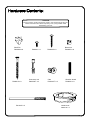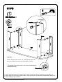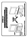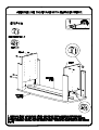
1
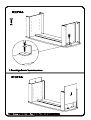
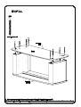
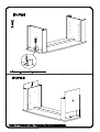
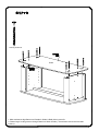
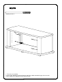
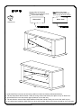
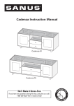
PLATINUM FURNITURE
MODEL PFPL
- Digital TV Stand
Assembly Instructions
BUS5305
BUS5305
Congratulations and thank you for purchasing your new Sanus
Platinum Furniture Product. If you have any questions regarding
this or any other Sanus product, please contact our customer
service department at (800)359-5520, or www.sanus.com. It is
not necessary to contact the retailer with any questions or
problems, as parts can be sent directly to you
We recommend that the unit is assembled on a soft surface
such as carpet. Please record your serial number in the space
provided below and retain this manual for future reference.
Please follow these assembly instructions. This will save you
time, make assembly easier and prevent possible damage to
your new Digital TV Stand. Assistance may be required for
some assembly procedures. Correct assembly is your
responsibility.
This unit was manufactured using ISO 9000 certified systems.
For improvement purposes, design and specifications are subject to
change without notice.
Serial No
CAUTION
There are many small components used in the construction of this unit.
These loose items should be kept away from young children while
assembling your unit.
Shelf Pin
P840048 x 8
P860015 x 8
P816145 x 4
P860121 x 1
Connector rod
P820016T x 8
P860035 x 6
Barrel nut
P840050 x 8
Cam
P820015T x 8
Wooden dowel
P800201 x 8
Cable Ducts
P840170 x 2
Insert wooden dowels into sides as shown.
x8
1. Fasten 8 Connector Rods into small holes in Top as shown.
Intersecting
hole
Important:
*When fitting the rails onto the top, ensure that the grooved
part of the rails are closest to the side edges of the top.
* The larger holes (cam holes) in the rails must always be
closest to the Top.
1. Insert black Barrel Nuts into smaller holes in Rails, ensuring slot in cap is aligned to intersecting hole.
2. Insert silver Cams into larger holes in Rails, ensuring that arrow on Cam points towards intersecting hole.
3. Press fit Rails to Top as shown.
Locking screw x8
Base
1. With assistance align Base onto Dowels in Sides & Rails & then press fit.
2. Fasten large Locking screws through Base into Sides & Rails ( Screw heads should be flush with
surface).
Following steps apply to both flat and curved front designs.
Glide x6
Screw x6
1. Fasten the glides to the base as shown.
Adjusting screw x 4
1. Turn unit over carefully.
2. Screw each Adjusting screw into Side by half of it's visible threaded length, then once this
is done, tighten all 4 Adjusting screws fully into Side.
Curved edge of the glass
shelves must be placed at front
for curved front design .
Glass shelf
Flat edge of the glass
shelves must be placed at
front for the flat front design .
Glass shelf
Shelf Pin x8
1. Insert Shelf Pins into holes at the lower positions of both the Sides (as illustrated above).
2. Tilt and slide Glass Shelf between Rails (ensuring frosted side down) and place on top of Shelf Pins.
3. Insert Shelf Pins into holes at the upper positions of one Side only.
4. Tilt and slide the second Glass Shelf between Side Rails. While holding one end of the shelf on pins
on one side insert remaining Shelf Pins into other side beneath Glass, then lower the shelf on top of the pins.
1. Press fit 2 Cable Ducts into large holes in the Base.
2. You have now completed the assembly of your new Digital TV stand.
NOTE: We recommend that all contents stored in or on this item of furniture be removed before shifting it. The
manufacturers will not be held liable for damage caused when furniture is shifted without first removing its contents.
If furniture is shifted we recommend that it is lifted not dragged.