1
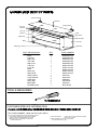
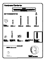
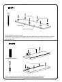
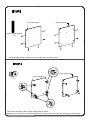
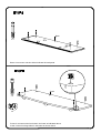
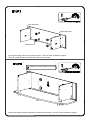
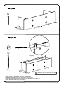
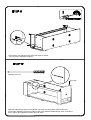
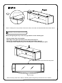
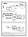
PLATINUM FURNITURE
MODEL PFV59s
Assembly Instructions
- Digital TV Stand
BUS5306
BUS5306
Congratulations and thank you for purchasing your new Sanus
Platinum Furniture Product. If you have any questions regarding
this or any other Sanus product, please contact our customer
service department at (800)359-5520, or www.sanus.com. It is
not necessary to contact the retailer with any questions or
problems, as parts can be sent directly to you
We recommend that the unit is assembled on a soft surface
such as carpet. Please record your serial number in the space
provided below and retain this manual for future reference.
Please follow these assembly instructions. This will save you
time, make assembly easier and prevent possible damage to
your new Digital TV Stand. Assistance may be required for
some assembly procedures. Correct assembly is your
responsibility.
This unit was manufactured using ISO 9000 certified systems.
For improvement purposes, design and specifications are subject to
change without notice.
Serial No
Angle bracket
Glass top
Angle bracket
Thin side
Left side
Long rail
Left front
Back
Right side
Glass shelf
Steel bracket
Base
Thin side
Glide (gray / black)
Right front
PART DESCRIPTION:
Base
Left side
Right side
Thin side
Right front
Left front
Long rail
Back
Glass top
Glass shelf
Steel bracket
Angle bracket
Cable duct
Gray glide
Black glide
Hardware pack
QTY
PART NUMBER
1
1
1
2
1
1
1
1
1
1
1
2
4
3
3
1
M20205A1PO
M20206A1ZS
M20207A1ZS
M20208A1ZS
M20209A1ZS
M20210A1ZS
M20211A1ZS
M20212A1PO
M20213A1PO
M20214A1PO
P816190
P816191A
P840200
P815034A
P815034
MH1181A0
TOOLS REQUIRED:
CUSTOMER SERVICE INFORMATION
THE TOLL FREE NUMBER WITHIN 14 DAYS OF PURCHASE.
TOLL-FREE NUMBER - (800) 359-5520 (USA ONLY)
THE FOLLOWING INFORMATION MUST BE SUPPLIED IN FULL:
1. YOUR NAME, ADDRESS AND TELEPHONE NUMBER.
2. PRODUCT MODEL NAME/NUMBER AND COLOR.
3. DESCRIPTION, PART NUMBER AND QUANTITY
OF REQUIRED PARTS.
-STORE THE UNIT WAS PURCHASED FROM.
-DATE OF PURCHASE.
5. SERIAL NUMBER OF THE UNIT PURCHASED.
(LOCATED ON REAR OF UNIT)
4. PURCHASE DETAILS:
Bump-on
P840022 x 18
B
Front edge
Glide (gray/black)
x6
Back edge
Base (underside)
Fasten 6 glides to the base as shown.
Note that there are 3 gray and 3 black glides. Use gray glides at front of the base if the stand is going to
be placed on a light colored floor. Use Black glides at the front if the stand is going to be placed on a
dark colored floor.
Left front panel
Large wooden dowels x 4
Right front panel
x6
Screw 3 connector rods into holes in left and right front panels as indicated above.
Press fit 2 large wooden dowels into large holes in left and right panels as shown.
Left side panel
Right side panel
Small wooden dowels
x 12
Press fit small wooden dowels into left and right sides as shown above.
Right side panel
Left side panel
x 12
Insert cams into large holes in left and right sides as shown.
Make sure arrows on the cams point towards the corresponding cam holes along the edges of the panels.
Back
x4
Screw 4 connector rods into holes indicated in back panel.
Base
x4
x2
Screw 4 connector rods into holes in the base as indicated above.
Insert 2 cams into large holes in the base as shown above.
Left side panel
Right side panel
Cable duct
Press fit the sides to the back as shown above. Turn the cams clockwise to tighten.
Press fit 4 cable ducts into large holes in the back as shown.
Assistance may be needed for this step.
Press fit the sides and back assembly onto the base as shown. Turn the cams clockwise to tighten.
C
x5
Fasten the back to the base as shown above.
x2
D
Long rail
x2
Assistance may be needed for this step.
Hold the long rail in between the sides as illustrated.
Insert the black barrel nuts into the holes in the long rail.
Ensure the holes in the sides are aligned with the holes in the long rail.
Fasten the sides to the long rail as shown.
Press fit the front panels to the sides and base as shown.
Turn the cams clockwise to tighten.
Adjusting screw x 4
Thin side
Slide thin sides down slots in front panels and back, ensuring silver surfaces face out.
Screw each adjusting screw into sides by half of it's visible threaded length, then once this is
done, tighten all 4 Adjusting screws fully into sides.
Steel bracket
Fit the long steel bracket into the rebate in the long rail and in the grooves in the sides as shown above.
Ensure the bracket is equally distanced from the sides on both ends.
A
x5
Once the bracket is adjusted in the sides, fasten it to the long rail using the screws shown above.
It is important that you hold the long rail against the steel bracket as you tighten the screws.
Bump-on(self adhesive)
x 18
Attach 18 bump-ons to top surface of the back, sides, front rails, and steel bracket where shown above.
Assistance may be needed for this step.
When placing the glass top on the unit, pay attention to the following tips:
* Ensure painted side is facing down.
* Back edge of the glass top must be flush with the back panel.
* Glass top's overhang at the left side must match that of the right side.
* Lift the glass when repositioning it, do not drag it as it could damage your glass.
Back edge of the glass top is flush with back panel.
Front edge
Above is the top view of the cabinet, indicating where the glass top should rest on the cabinet.
A
x4
Fasten the angle brackets to the back as shown above.
Note - the angle brackets are essential for the strength of the stand.
Assistance will be needed for this step.
x6
Insert 2 shelf pins into the bottom holes in the right side. Place a piece of polystyrene (from the pack) onto
the base as shown above (Alternatively you could use a soft rag). Tilt the glass to one side and rest it on top
of the polystyrene.Then carefully push the glass inside the cabinet and rest the right side on the shelf pins.
Then raise the left side of the glass up and insert the remaining of the shelf pins into the left side and back.
Lower the glass onto the shelf pins.
NOTE: We recommend that all contents stored in or on this item of furniture be removed before shifting it. The
manufacturers will not be held liable for damage caused when furniture is shifted without first removing its contents.
If furniture is shifted we recommend that it is lifted not dragged.