1
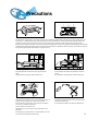
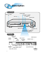
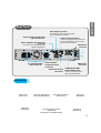
DIGITAL HOME
THEATER SYSTEM
HT-SK6
Instruction Manual
COMPACT
VIDEO
DIGITAL AUDIO
COMPACT
DIGITAL VIDEO
SAMSUNG ELECTRONICS AMERICA, INC.
SERVICE DIVISION
400 Valley Road, Suite 201
Mount Arlington, NJ 07856
1-800-SAMSUNG (1-800-726-7864)
www.samsungusa.com
AH68-01241Q
Safety Warnings
CLASS 1 LASER PRODUCT
KLASSE 1 LASER PRODUKT
LUOKAN 1 LASER LAITE
KLASS 1 LASER APPARAT
PRODUCTO LASER CLASE 1
CAUTION
RISK OF ELECTRIC SHOCK.
DO NOT OPEN
CAUTION:
TO REDUCE THE RISK OF ELECTRIC
SHOCK, DO NOT REMOVE REAR COVER.
NO USER SERVICEABLE PARTS INSIDE.
REFER SERVICING TO QUALIFIED
SERVICE PERSONNEL.
Note to CATV system installer :
This reminder is provided to call the CATV system
installer’s attention to Section 820~40 of the NEC
which provides guidelines for proper grounding and,
in particular, specifies that the cable ground shall be
connected to the grounding system of the building,
as close to the point of cable entry as practical
CLASS 1 LASER PRODUCT
This Compact Disc player is classified as a CLASS 1
LASER product.
Use of controls, adjustments or performance of
procedures other than those specified herein may result
in hazardous radiation exposure.
CAUTION-INVISIBLE LASER RADIATION WHEN OPEN
AND INTERLOCKS DEFEATED, AVOID
EXPOSURE TO BEAM.
This symbol indicates that dangerous voltage which can cause electric shock is present inside
this unit.
This symbol alerts you to important operating and maintenance instructions accompanying
the unit.
WARNING: To reduce the risk of fire or electric shock, do not expose this appliance to rain or moisture.
CAUTION: TO PREVENT ELECTRIC SHOCK, MATCH WIDE BLADE OF PLUG TO WIDE SLOT, FULLY
INSERT.
1
Precautions
Ensure that the AC power supply in your house complies with the identification sticker located on the back of your player. Install your player
horizontally, on a suitable base (furniture), with enough space around it for ventilation (3~4inches). Make sure the ventilation slots are not
covered. Do not stack anything on top of the player. Do not place the player on amplifiers or other equipment which may become hot.
Before moving the player, ensure the disc tray is empty. This player is designed for continuous use. Switching off the DVD player to the stand-by
mode does not disconnect the electrical supply. In order to disconnect the player completely from the power supply, remove the main plug from
the wall outlet, especially when left unused for a long period of time.
During thunderstorms, disconnect AC main plug from the wall
outlet.
Voltage peaks due to lightning could damage the unit.
Do not expose the unit to direct sun radiation or other heat
sources.
This could lead to overheating and malfunction of the unit.
Phones
Protect the player from moisture(i.e. vases) , and excess heat(e.g.fireplace) or
equipment creating strong magnetic or electric fields (i.e.speakers...).
Disconnect the power cable from the AC supply if the player malfunctions.
Your player is not intended for industrial use.
The battery used with this product contain chemicals that are
harmful to the environment.
Do not dispose of batteries in the general household trash.
Use of this product is for personal use only.
Condensation may occur if your player or disc have been stored in cold
temperatures.
If transporting the player during the winter, wait approximately 2 hours until
the unit has reached room temperature before using.
2
Safety Instructions
READ INSTRUCTIONS
All the safety and operating instructions should be
read before the appliance is operated.
RETAIN INSTRUCTIONS
The safety and operating instructions should be
retained for future reference.
HEED WARNINGS
All warnings on the appliance and in the operating
instructions should be adhered to.
FOLLOW INSTRUCTIONS
All operating and use instructions should be
followed.
WATER AND MOISTURE
Do not use this video product near waterfor example, near a bathtub, wash bowl,
kitchen sink, or laundry tub, in a wet basement,
or near a swimming pool, and the like.
OVERLOADING
Do not overload wall outlets and extension cords as
this can result in the risk of fire
or electric shock.
VENTILATION
Slots and openings in the cabinet are provided
for ventilation and to ensure reliable operation of the
video product and to protect it from overheating
these openings must not be blocked or covered.
The openings should never be blocked
by placing the video product on a bed, sofa, rug, or
other similar surface. This video product
should never be placed near or over a radiator or
heat register.
This video product should not be placed
in a built-in installation such as a bookcase
or rack unless proper ventilation is provided
or the manufacturer's instructions have been
followed.
POWER CORD PROTECTION
Power-supply cords should be routed so that
they are not likely to be walked on or pinched
by items placed upon or against them paying
particular attention to cords at plugs,
convenience receptacles, and the point where
they exit from the appliance.
3
CLEANING
Unplug this video product from the wall outlet
before cleaning. Do not use liquid cleaners
or aerosol cleaners. Use a damp cloth for cleaning.
LIGHTNING
For added protection of this video product
receiver during a lightning storm, or when
it is left unattended and unused for long
periods of time, unplug it from the wall outlet
and disconnect the antenna or cable system.
This will prevent damage to the video product
due to lightning and power-line surges.
OBJECT AND LIQUID ENTRY
Never push objects of any kind into this
product through openings as they may touch
dangerous voltage points or short-out parts
that could result in a fire or electric shock.
Never spill liquid of any kind on the video
product.
ACCESSORIES
Do not place this video product on an unstable cart,
stand, tripod, bracket, or table.
The video product may fall, causing serious injury to
a child or adult, and serious damage
to the appliance.
Use only with a cart, stand, tripod, bracket,
or table recommended by the manufacturer,
or sold with the video product. Any mounting
of the appliance should follow the manufacturer's
instructions and should use a mounting accessory
recommended by the manufacturer.
CART
An appliance and cart combination should be moved
with care. Quick stops, excessive force, and uneven
surfaces may cause the appliance and cart
combination to overturn.
POWER SOURCES
This video product should be operated only from the
type of power source indicated
on the marking label. If you are not sure
of the type of supply to your home, consult your
appliance dealer or local power company.
For video products intended to be operated from
battery power, or other sources, refer
to the operating instructions.
POWER LINES
An outside antenna system should not be located in
the vicinity of overhead power lines or other electric
light or power circuits,
or where it can fall into such power lines
or circuits. When installing an outside antenna
system, extreme care should be taken to keep from
touching such power lines or circuits as contact with
them might be fatal.
POLARIZATION
This video product is equipped with a polarized
alternating current line plug (a plug having one blade
wider than the other.) This plug will fit into the power
outlet only one way.
This is a safety feature. If you are unable
to insert the plug fully into the outlet, try reversing the
plug. If the plug should still fail to fit, contact your
electrician to replace your obsolete outlet. Do not
defeat the safety purpose of the polarized plug.
OUTDOOR ANTENNA GROUNDING
•If an outside antenna is connected to the
antenna terminal, be sure the antenna system
is grounded so as to provide some protection
against voltage surges and built-up static
charges.
•In the U.S.A section 810 of the National
Electrical Code, ANSI/NFPA No. 70-1984,
provides information with respect to proper
grounding of the mast and supporting
structure, grounding of the lead-in wire
to an antenna discharge unit, size of grounding
conductors location of antenna discharge unit,
connection to grounding electrodes, and
requirements for the grounding electrode.
See the figure below.
ATTACHMENTS
Do not use attachments not recommended
by the video product manufacturer as they may
cause hazards.
SERVICING
•Do not attempt to service this product yourself
as opening or removing covers may expose
you to dangerous voltage or other hazards.
•Refer all servicing to qualified service personnel.
REPLACEMENT PARTS
When replacement parts are required, be sure the
service technician has used replacement parts
specified by the manufacturer or having the same
characteristics as the original part. Unauthorized
substitutions may result in fire, electric shock or other
hazards.
ANTENNA
LEAD IN WIRE
GROUND
CLAMP
ELECTRIC
SERVICE
EQUIPMENT
ANTENNA
DISCHARGE UNIT
(NEC SECTION. 810-20)
GROUNDING CONDUCTORS
(NEC SECTION 810-21)
GROUND CLAMPS
POWER SERVICE GROUNDING
ELECTRODE SYSTEM
(NEC ART 250, PART H)
SAFETY CHECK
Upon completion of any service or repairs
to this video product, ask the service technician to
perform safety checks to determine that the video
product is in proper operating condition.
DAMAGE REQUIRING SERVICE
Unplug this video product from the wall outlet and
refer servicing to qualified service personnel under the
following conditions.
a. When the power-supply cord or plug is damaged.
b. If liquid has been spilled, or objects have
fallen into the video product.
c. If the video product has been exposed to rain
or water
d. If the video product does not operate normally
by following the operating instructions.
Adjust only those controls that are covered
by the operating instructions as an improper
adjustment of other controls may result
in damage and will often require extensive
work by a qualified technician to restore
the video product to its normal operation.
e. If the video product has been dropped
or the cabinet has been damaged.
f. When the video product exhibits a distinct
change in performance - this indicates
a need for service.
HEAT
This video unit should be situated away from heat
sources such as radiators, stoves, or other products
(including amplifiers) that produce heat.
4
DVD (Digital Versatile Disc) offers fantastic audio and video, thanks to Dolby
VIDEO
1
~ 6
Digital surround sound and MPEG-2 video compression technology. Now you can
enjoy these realistic effects in the home, as if you were in a movie theater or concert
hall.
DVD players and the discs are coded by region. These regional codes must match in
order for the disc to play. If the codes do not match, the disc will not play.
The Region Number for this player is given on the rear panel of the player.
(Your DVD player will only play DVDs that are labeled with identical region codes.)
Do not use the following types of disc!
• LD, CD-G, CD-I, CD-ROM and DVD-ROM cannot be played on this player.
•
If such discs are played, a "WRONG DISC FORMAT" message appears on the TV screen.
DVD discs purchased abroad may not play on this player.
If such discs are played, a "WRONG REGION CODE" message appears on the TV screen.
Copy Protection
• Many DVD discs are encoded with copy protection. Because of this, you should only connect your
•
5
DVD player directly to your TV, not to a VCR. Connecting to a VCR results in a distorted picture
from copy-protected DVD discs.
This product incorporates copyright protection technology that is protected by methods claims of certain
U.S. patents and other intellectual property rights owned by Macrovision Corporation and other rights
owners. Use of this copyright protection technology must be authorized by Macrovision Corporation, and
is intended for home and other limited viewing uses only unless otherwise authorized by Macrovision
Corporation. Reverse engineering or disassembly is prohibited.
Contents
CHAPTER 4.
SETUP
Safety Warnings
Precautions
Safety Instructions
Description
Remote Control
1
2
3
7
9
Setting up the Language Features
System Setup
Speaker Setup
To set up Speaker Balance
Creating Realistic Sound Fields
Dolby Pro Logic II decoder
DSP (Digital Signal Processor) Modes
CHAPTER 2.
Connecting the Speakers
Connect Video to TV
Connecting the FM and AM(MW/LW) Antennas
AUX Connections
Before Using the DVD Player
Controlling a TV with the Remote
P.SCAN(Progressive Scan) Function
11
13
14
15
16
17
17
18
CHAPTER 5.
RADIO OPERATION
Listening to the Radio
Presetting stations
SETUP
Connecting your System to the Power Supply
Adjusting DSP Sound Parameters
32
33
35
37
38
39
41
42
42
OPERATION
To increase Effect level
CONNECTIONS
PREPARATION CONNECTIONS
CHAPTER 1.
PREPARATION
43
44
CHAPTER 3.
OPERATION
MP3-CD Playback
Forward/Reverse Searching
Slow Playback/Checking the Remaining Time
Repeat Playback
Using Disc Menu/Title
Zoom/Angle Functions
Program Playback
Sleep/D.R.C Function
Listening on headphones
CHAPTER 6.
MISCELLANEOUS
Troubleshooting
Cautions on Handling and Storing Discs
Disc Type and Protection
Specifications
Warranty
45
47
48
49
50
MISCELLANEOUS
Selecting the Audio Language/Subtitle Language
19
21
23
24
25
26
27
28
29
31
31
RADIO OPERATION
DVD Playback
6
Description
Front Panel
Function button
Power (
) button
Play/Pause (
) button
Stop ( ) button
Disc Tray
Volume control
Open/Close button
Headphone Jack
Tuning Down & Skip ( ) buttons
Tuning Up & Skip ( ) buttons
Display
LINEAR PCM
indicator
DSP
PBC indicator
P.SCAN
indicator
indicator
TITLE
PROGRAM
indicator
indicator
P . SCAN
L
C
LINEAR PCM DSP TITLE
R
LFE
LS
S
PRGM
STEREO indicator
ST
TUNED
PRO LOGIC
kHZ
MHZ
D I G ITAL
RS
SPEAKER
indicator
DTS Disc indicator
DOLBY DIGITAL indicator
PRO LOGIC indicator
7
PBC
TUNER indicator
System Status Display
RADIO
FREQUENCY
indicator
PREPARATION
Rear Panel
Video Output Connector
Connect the TV's video input jacks (VIDEO
IN) to the VIDEO OUT connector.
External Video Component
Input Connectors
S-Video Output Connector
If the TV is equipped with an S-Video input
connector (S-VIDEO IN), connect it to the
player's S-Video output jack.
External Digital Component Input
Connector
AM Antenna
Connector
Use this to connect external equipment
capable of digital output.
5.1 Channel Speaker
Output Terminals
External Audio
Component Input
Connector
Subwoofer Preout
Connector
FM Antenna
Connector
COMPONENT VIDEO
OUTPUT/INPUT jacks
Connect a TV with component
video inputs to these jacks.
Accessories
Remote Control
(AH59-01101F)
FM Antenna
(AH42-00004A)
Audio Cable (AH39-40001U)
Video Cable (AH39-40001V)
Audio Cable (AH39-40001V)
Subwoofer only
Front/Center Speaker Cord 3EA
(AH39-00375B)
Rear Speaker Cord 2EA (AH39-00375C)
AM Antenna
(AH42-20001P)
User's Manual
(AH68-01241Q)
8
Remote Control Unit
DVD POWER button
TV
TV Power button
DVD button
TV/VIDEO
TUNER button
TV/VIDEO button
Channel
AUX button
TV Channel Selection button
Volume
Open/Close button
TV Volume Control button
Title button
Play/Pause button
Menu button
Stop button
Audio MO/ST(mono/stereo) button
Tuning Preset/CD Skip button
Subtitle button
Tuning Up/Down/CD Search button
Display button
Return button
Direction/Enter button
Volume Control buttons
Speaker output volume control
DSP/DPL II Mode button
Sleep button
Mute button
DSP/DPL II Effect button
Sound Edit button
SPK Mode button
Pro Logic II button
Test Tone button
Number(0~9) buttons
Slow button
Angle button
Repeat button
Clear button
Step button
Zoom button
Setup/P.Scan Adjust button
P.Scan button
Remain button
Repeat A↔B button
Go To button
Program button
D.R.C button
9
Insert Remote Batteries
CAUTION
PREPARATION
1
Remove the battery cover on the back of the remote by pressing
down and sliding the cover in the direction of the arrow.
2
Insert two 1.5V AAA batteries, paying attention to the correct polarities (+
and –).
3
Replace the battery cover.
Follow these precautions to avoid leaking or cracking cells:
• Place batteries in the remote control so they match the polarity:(+) to (+)and (–)to (–).
• Use the correct type of batteries.Batteries that look similar may differ in voltage.
• Always replace both batteries at the same time.
• Do not expose batteries to heat or flame.
Range of Operation of the Remote Control
The remote control can be used up to approximately
23 feet/7 meters in a straight line. It can also be
operated at a horizontal angle of up to 30° from the
remote control sensor.
30
To open the remote control cover,
push the top of the cover, then slide
downward.
30
7~10m
10
Connecting the Speakers
Connect the supplied speaker system using the supplied speaker cords.
- Make all connections with the power turned off to the unit to protect the speakers.
1
Check the location of the terminals on the main unit and on the rear of the
speakers before connecting the Front, Rear, and Center Speakers.
2
Use the supplied audio cord to connect the SUBWOOFER PREOUT on the
rear of the main unit to the LINE IN on the rear of the speaker.
- Connect the red cord to the red(+)terminal and the black cord to the black(-) terminal.
- Make sure the positive (+) and negative (-) speaker wires are not mixed.
•
After installation is complete, tie up or taping down long, loose electrical cords.
Ideal Speaker Placement
Left front
speaker
Center speaker
Right front
speaker
Subwoofer
Front Speakers
Set the front speakers so that their tweeters (high-range) are
aligned at about ear level and at a horizontal angle of 45° to the
prime listening position.
Center Speaker
Left rear
speaker
Right rear
speaker
Ideally the center speaker should be positioned with its top
surface flush with the front speakers. However, you may place
the speaker either on top or near the bottom of your TV set.
Vibration caused by the center speaker can disrupt the picture
if it is placed directly on the television. Put the center speaker
on a rack or shelf.
Rear Speakers
Set the rear speakers further back, parallel to the walls,
at 60 to 90 centimeters (2 to 3 feet) above prime listening
position ear level.
If the space behind the listening position is insufficient
(i.e., too close to the wall), place the rear speakers facing
each other on either side.
Subwoofer Speaker
Place the subwoofer on the floor near the TV or mount it
on a rack, free from vibration and instability.
• Please refer to the KLIPSCH Operation Manual for details on using the speakers.
11
1
Loosen the speaker terminal by
turning it counterclockwise.
2
Insert the speaker wire into
the terminal.
3
Tighten the speaker terminal
by turning it clockwise.
1
2
3
CONNECTIONS
Subwoofer
Right rear speaker Left rear speaker
Center speaker
LINE IN
R
(—)
(—)
(+)
(—)
L/LFE
(+)
(+)
Audio Cable (supplied)
(—)
(+)
Right front speaker
1
Press and hold the
terminal tab.
2
Insert the speaker cord.
3
Release your finger.
1
(—)
(+)
Left front speaker
2
Red
3
Black
12
Connect Video to TV
TV
Composite
Video
*
S-Video
Component
Video
Depending on your TV, Component Video input connectors may be marked as DVD Video input connectors.
Composite Video (Good Quality)
Connect the supplied video cable from the VIDEO OUT jack on the back panel of the
system to the VIDEO IN jack on your television.
S-Video (Better Quality)
If you television is equipped with an S-Video input, connect an S-Video cable (not supplied)
from the S-VIDEO OUT jack on the back panel of the system to the S-VIDEO IN jack on
your television.
Component Video (Best Quality)
If your television is equipped with Component Video inputs, connect a component video
cable (not supplied) from the Pr, Pb and Y jacks on the back panel of the system to the
corresponding jacks on your television.
•
13
When the Progressive scan mode is selected, the VIDEO and S-VIDEO outputs do not feed
any signals. See page 18 to select Progressive Scan.
Connecting the FM and AM(MW/LW) Antennas
1
2
3
If AM reception is
poor, connect an
outdoor AM
antenna(not
supplied).
AM Loop Antenna
(supplied)
CONNECTIONS
ANTENNA
If FM reception is poor,
connect an outdoor FM antenna
(not supplied).
FM Antenna (supplied)
Snap the tabs on the loop into the
slots of the base to assemble the
AM loop antenna.
Cooling fan (See “About Cooling Fan” below.)
FM antenna connection
1. Connect the FM antenna supplied to the FM 75
COAXIAL terminal as temporary measure.
2. Slowly move the antenna wire around until you
find a location where reception is good, then
fasten it to a wall or other rigid surface.
• If reception is poor, connect an outdoor antenna.
Before attaching a 75 coaxial cable (with a standard
type connector), disconnect the supplied FM antenna.
(About the cooling fan)
A cooling fan is mounted on the rear panel of the center unit to
prevent abnormal temperature inside the center unit, thus assuring
normal operation. The cooling fan automatically starts rotating to
supply external cool air to the inside of the center unit when the
internal temperature exceeds the specified limit.
AM(MW/LW) antenna connection
1. Connect the AM loop antenna supplied
to the AM and
terminals.
2. If reception is poor, connect an outdoor
single vinyl-covered wire to the AM
terminal. (Keep the AM loop antenna
connected).
For safety, observe the following carefully.
• Make sure there is good ventilation around the center unit. Poor
ventilation could overheat and cause damage.
• DO NOT block the cooling fan and the ventilation openings or
holes. (If they are blocked by a newspaper or cloth, etc., the heat
may not be able to escape.)
14
AUX Connections
External Digital
Components
TV
For connection to external
equipment with digital output.
Example: CD recorders, MD (Mini Disc) D/A
converters or other components equipped
DIGITAL OUT
with digital output jacks
VIDEO IN
To view pictures from
external input (AUX 1 ,
AUX 2 ), first connect
the VIDEO IN jack and
then connect the VIDEO
OUT jack.
(not supplied)
Optical Cable
Audio Cable (Red/White)
If the external analog
component has only one
output jack, you may connect
either L or R.
Video Cable
External Analog
Components
CAUTION
R
L
VIDEO OUT
Connect to external equipment with
analog output.
Example: VCR, TV, etc.
• Always connect the video and
To Play External Digital/Analog Equipment
Press AUX on the remote control to select DIGITAL IN, AUX1, or AUX2.
Press Function on the main unit to select DIGITAL IN, AUX1, or AUX2.
• Each time the button is pressed the mode switches as follows: FM ➞ AM ➞ DVD ➞
DIGITAL IN ➞ AUX 1 ➞ AUX 2.
15
audio connection cables to the
equivalent colored jack.
Before Using the DVD Player
Your DVD player is capable of playing DVD, VCD, and CD discs.
User instructions may vary depending on the type of disc. Read the instructions
carefully before use.
1
2
before
use
Select a video mode by
pressing the TV/VIDEO
button.
Press the DVD button
to select the DVD input
function.
TV/VIDEO
DVD
TV
• The “WAIT” message that appears on the display for about 4~5 seconds when turning on
the power or selecting a DVD function indicates a stabilization period for optimizing the
condition of your DVD player. While the message is being displayed, other buttons
remain inactive.
•
When the power is not turned on, press down the Stop (
over 5 seconds.
The product will be initialized to its optimum state.
•
Some operational features such as the Speaker mode, Test tone, Volume, etc.
will not be displayed on the TV screen.
) button on the main unit for
TV Broadcast System
• This device is designed to work with the NTSC video format.
• For normal playback, the video format a DVD disc is recorded in must
coincide with your TV's video format.
16
CONNECTIONS
Turn on the power
Prepa- to your DVD player
rations and TV.
3
Controlling a TV with the Remote
You can operate your TV by adjusting the DVD remote signal .
1
2
3
Turn on the TV.
Point the DVD’s remote at the TV.
TV
While holding the
code for your brand.
button down, enter the
• If there is more than one code listed in the table,
enter one at a time to determine which code works.
example : For SAMSUNG 1TVs
While holding down the
enter
.
4
TV
button,
Code
Brand
Code
Brand
01
02
03
04
05
06
07
08
09
10
11
12
13
14
15
SAMSUNG 1
SHARP 2
SONY
MAGNAVOX
SANYO 1
LG 2
RCA
LG 1
TOSHIBA
HITACHI
JVC
PANASONIC 1
MITSUBISHI 2
SAMSUNG 2
SAMSUNG 3
16
17
18
19
20
21
22
23
24
25
26
27
28
29
SHARP 1
ZENITH
LG 3
DAEWOO 8
SANYO 2
EMERSON
SHARP 3
SAMSUNG 4
MATSUSHITA
NOBLEX
TELEFUNKEN
NEWSAN
LOEWE
RCA2
If the TV turns off, setup is complete.
• The remote may not be able to
control every model TV of the
brands listed.
Connecting your System to the Power Supply
The AC Cord must be plugged into an appropriate socket.
Before plugging your system into an AC outlet, you must check the voltage.
1. Plug the AC Cord on the rear of the system into an appropriate outlet.
2. Press the On/Standby button to switch your DVD Player system on.
17
P.SCAN(Progressive Scan) Function
Unlike a regular Interlace Scan in which two fields of picture information are alternated to
create the entire picture (odd scan lines, then even scan lines), Progressive Scan uses
one field of information (all lines displayed in one pass) to create a clear and detailed
picture without visible scan lines. To enjoy a progressive scan video, connect a TV or
monitor that supports a progressive scan input to this device.
CONNECTIONS
While the player is in the Stop mode, hold the P.SCAN
button down for longer than 1 second.
• The selection switches back and forth between "P.SCAN" and "I.SCAN"
each time the button is held down for a minimum of 1 second.
• The previous mode is indicated in the display first, followed by the
selected mode in about a second.
P.Scan Adj (Progressive Scan Adjusting)
This function allows you to optimize the picture quality when it becomes poor due to screen distortion or
discs containing erroneous data.
Press the Setup/P .Adj button. (Play mode only)
• Each time the Setup/P .Adj button is pressed, the following appears on the TV screen:
What is Progressive (or Non-Interlaced) Scanning?
Interlaced Scan (1 FRAME = 2 FIELDS)
In interlaced-scan video, a frame consists of two
interlaced fields (odd and even), where each field
contains every other horizontal line in the frame.
The odd field of alternating lines is displayed first, and
then the even field is displayed to fill in the alternating
gaps left by the odd field to form a single frame.
One frame, displayed every 1/30th of a second, contains
two interfaced fields, thus a total of 60 fields are
displayed every 1/60th of a second each.
The interlaced scanning method is intended for capturing
a still object.
Progressive Scan (FULL FRAME)
The progressive scanning method scans one full frame of
video consecutively down the screen, line by line.
As opposed to the interlaced scanning process by which a
video image is drawn in a series of passes, you get an
entire image drawn at one time.
The progressive scanning method is desirable for dealing
with moving objects. A camera that has the ability to
capture moving objects is called a "full frame shutter
camera".
• This function works only on TVs equipped with component video inputs (Y, Pr, Pb) that
support Progressive Video. (It does not work on TVs with conventional component inputs,
i.e., non-progressive scan TVs.)
• Depending on the brand and model of your TV, this function may not work.
18
DVD Playback
1
Press the Open/Close( ) button
to open the disc tray.
2
Insert a disc.
VIDEO
• Place a disc gently into the tray with the
disc’s label facing up.
3
Press the Open/Close( ) button
again to close the disc tray.
• Playback starts automatically.
Stopping Playback
Pausing Playback
Press the Play/Pause (
playback.
) button during
• To resume, press the Play/Pause (
) button during playback.
• During playback, when the Stop (
)
button again.
Depending on the disc, the initial disc
information screen may look different
from disc to disc.
19
Press the Stop (
)button is pressed,
the position is stored in the memory, and
STOP is
shown on the display.
When the Play/Pause (
) button or Return button is
pressed subsequently , playback resumes from the
position at which it was stopped.
• If the Stop ( ) button is pressed a second time, the
resume play memory function is canceled, and
STOP is shown on the display. When the Play/Pause
(
)button is pressed, playback starts from the
beginning.
Display
Using the On-Screen Display
Press the Display button on the remote.
Display
T1/2
VIDEO
DVD indicator
C 1/8
00:00:00
TITLE indicator
CHAPTER indicator TITLE ELAPSED
indicator
VIDEO
ENG
ENG 1/3
SUBTITLE LANGUAGE
indicator
AUDIO LANGUAGE
indicator
OFF
OPERATION
Display
1/1
ANGLE indicator
REPEAT indicator
DISC TYPE indicator
Display
The On-Screen Display disappears.
Mute
What is a Title?
Turning the sound off temporarily?
A movie contained in a
DVD disc.
Press the Mute button during playback.
What is a Chapter?
Each Title on a DVD
disc is divided into
several smaller sections
called "chapters".
• This operation may be useful when you need
to greet guests or answer the telephone.
If the player is left for more than 3 minutes
in pause mode, it will stop.
20
MP3-CD Playback
This system has a built-in MP3 decoder.
You can play back MP3 tracks (files)recorded on CD-Rs, CD-RWs, and CD-ROMs.
What is MP3? MP3 is an abbreviation of Motion Picture Experts Group (or MPEG) Audio Layer 3.
MP3 is simply a file format with a data compression ratio of 1:10 (128 Kbps*). That means,by using
MP3 format, one CD-R or CD-RW can contain 10 times as much data volume as a regular CD.
Starting Playback
• It is recommended you turn on your TV when playing back an MP3-CD.
1
Press the Open/Close( ) button
to load a disc.
2
Press the Play/Pause(
) button.
• After detecting the disc, playback starts.
• The on-screen bar and the contents
recorded on the MP3-CD will be shown
on the TV if it is turned on.
To stop during playback
Press the Stop (
) button.
CD-R MP3 DISC
• Only CD-R discs with MP3 files in ISO 9660 or Joliet format can be played.
• The file name of the MP3 file may not be longer than 8 characters and should contain no blank spaces or special
characters.
• Use discs recorded with a compression/decompression data rate greater than 128Kbps.
• Only files with the ".mp3" and ".MP3" extensions can be played.
• Only a consecutively written Multisession disc can be played. If there is a blank segment in the Multisession disc,
the disc can be played only up to the blank segment.
• If the disc is not closed, it will take longer to begin playback and not all of the recorded files may be played.
• For files encoded in Variable Bit Rate (VBR) format, i.e. files encoded in both low bit rate and high bit rate (e.g.,
32Kbps ~ 320Kbps), the sound may skip during playback.
21
Depending on the recording mode, some MP3-CDs cannot be played.
Operations Using the On-Screen Display
Turn on your TV when playing back an MP3 disc.
When the loaded MP3 disc is recognized, the following
on-screen display appears on the TV screen.
(The contents of this on-screen display vary according to
the disc — the way MP3 tracks were recorded on the
disc.)
Button
ENTER,
To do
Start playback or go into a directory.
▲/ ▼
Select a track or directory.
CD-R/RW playback compatibility
• Your DVD player can also play CD-R and CD-
OPERATION
RW discs recorded in digital audio format.
When recording your own CD-R or CD-RW
discs, make sure that the recording session is
properly terminated, or they will not be
playable. (Depending on disc properties and
recording quality, some CD-R/RW may not be
playable.)
• CD-RW has a lower reflection rate than CD-R
media and consequently it will take a longer to
read CD-R discs.
• CD-RW discs recorded at high speed tend to
be difficult for the DVD player to read. If the
recording speed for the CD-RW disc is not
predetermined, write it at low speed.
Repeat
Repeating Playback
On an MP3 disc, Repeat A↔B cannot be used.
You can enjoy only repeat play.
• Each time you press the button, repeat mode
changes as follows:
Press the REPEAT button.
The indication corresponding to the selected mode
appears on the TV screen.
REPEAT:RANDOM
: All tracks recorded on the disc will be played once in random order.
REPEAT:ONE
: Current track will be repeated.
REPEAT:DIR
: Tracks in the current directory will be repeated.
REPEAT:DISC
: All tracks on the disc will be repeated.
REPEAT OFF
: Repeat play is canceled.(Normal play is resumed.)
22
Forward/Reverse Searching
During playback, you can search quickly through a chapter or track for a specific scene
or tune.
button is pressed
Each time the
button is pressed
▲
▲
Each time the
button.
▲
▲
and
▲
▲
Press the
▲
▲
Multi-Speed Playback
X2
X2
X4
X4
X8
X8
PLAY
PLAY
and
▲
▲
Press the
▲
▲
Skipping through a Chapter
button.
• Each time the button is pressed during playback, it moves to the next
or previous chapter and plays it.
SEARCH
SEARCH
Step
Playing Frame by Frame
Press the Step button.
• The picture moves forward one frame each time the button is pressed.
23
No sound is heard during
high-speed playback, slow
playback, and step motion.
Slow Playback/Checking the
Remaining Time
Playing Slowly
Slow
Press the Slow button.
Each time the Slow button is pressed
SLOW 1/2
SLOW 1/4
The slow playback speed changes
and the selections (1/2X, 1/4X, 1/8X,
1/16X and normal play) are repeated.
OPERATION
PLAY
Remain
Checking the Remaining Time
Press the Remain button.
• For checking the total and remaining time of a
title or chapter being played.
Each time the Remain button is pressed
TITLE TIME
TRACK TIME
REMAIN TIME : TITLE
REMAIN TIME : TRACK
CHAPTER TIME
DISC TIME
REMAIN TIME : CHAPTER
REMAIN TIME : DISC
24
Repeat Playback
Repeat playback allows you to repeat a chapter, title, or track.
Repeat
Playing Repeatedly
Press the Repeat button.
Each time the Repeat button is pressed
• Repeat playback operation is not possible with version 2.0 VCD discs if PBC is turned on.
To operate this feature, press the MENU button, and then select "PBC OFF".
A↔B Repeat Playback
1
2
Press the Repeat A↔B button at the
beginning (A) of the segment you want to
review.
Press the Repeat A↔B button again at
the end (B) of the segment you want to
review.
• The segment will begin repeating.
To return to normal playback
Press the Repeat A<–>B button again.
25
Repeat
A B
Using Disc Menu/Title
Menu
To Select the Disc Menu
You can use the menus for the audio language,
subtitle language, profile, etc. DVD menu contents
differ from disc to disc.
1
2
▲
Press the Menu button during
playback.
3
Press the Enter button.
▲
Use the Up/Down (▲ / ▼ ) or
Left/Right( / ) button to
access the different features.
• The Menu Screen appears.
• When playing VCD version
• The selected item will play.
OPERATION
2.0, you can operate it using
PBC On/Off function.
Title
Using the Title Menu
For DVDs containing multiple titles, you can
view the title of each movie.
Depending on the disc, this function may either
not work at all, or may work differently.
Go To
To move directly to a title, chapter, or time
Press the Go To button.
Press Number(0~9) buttons or the
Left/Right ( / ) button.
▲
2
• Each time the button is pressed, it repeats as shown below.
▲
1
• Each the buttons are pressed the desired
scene is located and then played.
VIDEO
TITLE
T1/2
C 1/8
00:00:00
VIDEO
T1/2
CHAPTER
C 1/8
00:00:00
VIDEO
TIME
T1/2
C 1/8
:
00:00:00
:
• Depending on the disc, the Title function
may not work.
26
Selecting the Audio Language/Subtitle Language
Audio
Selecting the Audio Language
MO/ST
Press the Audio button.
• Depending on the number of languages recorded on a DVD disc, a different audio language
(ENGLISH, SPANISH, FRENCH, etc.) is selected each time the button is pressed.
ENG
VIDEO
ENG 1/3
OFF
1/1
SPA 2/3
FRE 3/3
• Depending on the disc, DTS or DIGITAL PRO LOGIC can be selected.
Subtitle
Selecting the Subtitle Language
Press the Subtitle button.
• Depending on the number of languages recorded on a DVD disc, a different subtitle
•
language (ENGLISH, SPANISH, FRENCH etc.) is selected each time the button is
pressed.
To make the subtitles disappear, select "OFF".
VIDEO
ENG 1/3
ENG 1/1
OFF
1/1
SPA 2/3
FRE 3/3
OFF
• If the word
•
27
INVALID appears on the TV screen while buttons are being
operated, that operation is not possible with that particular disc.
Depending on the disc, the audio or subtitle language function may not work.
Zoom/Angle Functions
To enlarge an image
Zoom
Press the Zoom button.
• Images can be enlarged 2x and 4x.
• During DVD playback, press the Zoom button
2
▲
▲
to zoom in 2X/4X/normal, in that order.
/ / ▲ / ▼ to move the enlarged
portion you want to watch.
• Press
OPERATION
• Only 2X zoom operation is possible during VCD playback.
Angle
Selecting the desired Screen Angle
Press the Angle button.
• This function only works with discs on which multiple angles have been recorded.
• During playback, press the Angle button to select the desired angle: 1/3, 2/3, 3/3,
normal, in that order.
OFF
1/3
2/3
3/3
28
Program Playback
Use this function with video and music CDs to play the tracks in a particular order.
Program
To Program Tracks in a particular order
2
3
Press the Program button.
Press the Enter button, then
use the Number buttons to
select the desired title.
PROGRAM MENU SELECT : ENTER
TITLE CHAPT
1
2
3
4
5
PREVIOUS
PLAY :
TITLE CHAPT
6
7
8
9
10
NEXT
FINISH : PROGRAM
▲
/
PROGRAM MENU SELECT : ENTER
TITLE CHAPT
1
1
2
3
4
5
PREVIOUS
PLAY :
4
Press the Enter button.
• The selected track number is
programmed and the cursor
moves to the next number.
PROGRAM MENU SELECT : ENTER
TITLE CHAPT
1
1
2
2
3
4
5
PREVIOUS
PLAY :
TITLE CHAPT
6
7
8
9
10
NEXT
FINISH : PROGRAM
To Leave the Programming Mode
29
/ ▲ / ▼ ) button.
TITLE CHAPT
6
7
8
9
10
NEXT
FINISH : PROGRAM
5
At this time, you can continue
programming if you want to.
• You can also use the Up/Down/
Left/Right (
/
▲
Left/Right (
▲
• You can also use the Up/Down/
Press the Enter button, then use
the Number buttons to select the
desired chapter.
▲
1
/ ▲ / ▼ ) button.
PROGRAM MENU SELECT : ENTER
TITLE CHAPT
1
2
1
2
3
4
5
PREVIOUS
PLAY :
TITLE CHAPT
6
7
8
9
10
NEXT
FINISH : PROGRAM
To Playback the
Tracks in
Programmed Order
• When programming more than
10 tracks, select EXT and
then press the Enter button.
The program selection screen
where you can program up to
10 additional tracks appears.
Press the Play/Pause
(
) button.
PROGRAM MENU SELECT : ENTER
TITLE CHAPT
1
2
1
1
2
2
1
7
3
2
3
4
2
4
5
PREVIOUS
PLAY :
6
7
8
9
10
TITLE CHAPT
4
1
6
2
3
4
5
5
1
2
NEXT
FINISH : PROGRAM
Press either the Program or Stop (
) button.
To Change the Program
1
2
3
Press the Clear button and
then press the Number
buttons.
• The cursor moves to the next
• You can also use the Left/Right
number when the Enter button
is pressed again.
/
) button.
OPERATION
4
(
▲
Press the Enter button to
select the title or chapter to be
changed.
▲
Press the Up/Down ( ▲ / ▼ )
button to select the track
number to be changed.
5
Press the Enter button.
Repeat steps 1-4 above to
change the program.
• The cursor moves to the
number below.
To delete the entire Program
• Press the Stop (
) button twice during playback.
• Press the Stop (
) button once when in the Stop mode.
• Press the Open/Close (
) button on the main unit.
The disc tray will open and then close.
The program will then be deleted.
When you have entered a
wrong number
Clear
You can program or change
particular tracks for VCD or CD
discs in the same manner.
Press the Clear button.
• When you want to delete a selection during
programming, select the track (or chapter, or title) to be
deleted and then press the Clear button.
30
Sleep/D.R.C Function
Sleep
To set up Sleep
Press the Sleep button.
• Each time the button is pressed the selection
toggles as follows: SLEEP 10 ➔ SLEEP 20
➔ SLEEP 30 ➔ SLEEP 60 ➔ SLEEP 90
➔ SLEEP 120 ➔ SLEEP 150 ➔ OFF.
What is the
Sleep function?
You can set the sleep time so that
the unit powers off automatically
after a preset period of time.
To Review Sleep Setting
• Press the Sleep button.
•
The remaining time for the selected Sleep time is displayed on the front panel.
Pressing the button once again changes the Sleep time from the last setting.
Activating Dynamic Range Compression
D.R.C
You can enjoy a powerful sound even at a low volume level by compressing the
dynamic range (difference between the maximum and minimum sounds).
From the remote control ONLY:
Press the D.R.C button.
• Each time you press the button,the dynamic range
compression mode alternates between on and off.
Select “D.R.C.ON ” while watching the DVD at night.
(You can obtain a powerful sound at a low volume.)
• This function takes effect only when Dolby Digital or
DTS Digital Surround is activated.
D I G ITAL
• When the Stop button is pressed, DRC is switched to Off.
Listening on headphones
Use headphones (not supplied) for private listening pleasure.
Connect the headphones to the HEADPHONE jack of the front panel.
• No sound is produced from the speakers.
• To prevent hearing damage, do not raise the volume level excessively when using headphones.
HEADPHONE jack
31
Setting up the Language Features
Using the DVD player's Setup function, you can customize the Menu
Language, Subtitle Language, and Disc Menu Language.
To set up the language feature
1
2
Press the Setup/P.Adj button from the stop
mode.
Press the Up/Down ( ▲ / ▼ ) button to select
the desired item.
LANGUAGES
SYSTEM
ENGLISH
AUDIO
CHINESE
CHINESE
CHINESE
SUBTITLE
MENU LANGUAGE
: Move
LANGUAGES
SYSTEM
OSD LANGUAGE
ENGLISH
AUDIO
CHINESE
CHINESE
CHI NESE
SUBTITLE
MENU LANGUAGE
Setup : Exit
: Move
Setup : Exit
OSD LANGUAGE
(PLAYER MENU LANGUAGE)
AUDIO
(AUDIO LANGUAGE)
SUBTITLE
MENU LANGUAGE
(SUBTITLE LANGUAGE)
If the Setup/P.Adj button is
pressed during the
language setup, it returns to
the stop mode again.
(DISC MENU LANGUAGE)
4
▲
Press the Enter button or Right (
SYSTEM
) button.
Press the Up/Down ( ▲ / ▼ ) button to select
the desired language and then press the Enter
button.
LANGUAGES
SYSTEM
OSD LANGUAGE
ENGLISH
OSD LANGUAGE
ENGLISH
ENGLISH
AUDIO
CHINESE
CHINESE
ENGLISH
AUDIO
CHINESE
CHINESE
CHINESE
FRENCH
SUBTITLE
MENU LANGUAGE
: Move
Setup : Exit
SETUP
3
LANGUAGES
OPERATION
OSD LANGUAGE
SUBTITLE
MENU LANGUAGE
: Move
GERMAN
Setup
: Exit
JAPANESE
To End the Language Features Setup
• Press the Setup/P.Adj button again.
32
System Setup
You can use the DVD player's Setup function to select the TV screen ratio,
rating limit, or digital output mode.
To Set up the System
1
2
LANGUAGES
▲
Press the Left/Right ( / )
button to select the system.
SYSTEM
LANGUAGES
OSD LANGUAGE
ENGLISH
TV SCREEN
AUDIO
CHINESE
CHINESE
CHINESE
RATING LEVEL
DIGITAL OUTPUT
SUBTITLE
MENU LANGUAGE
: Move
Press the Up/Down ( ▲ / ▼ )
button to select the desired
item.
▲
From the stop mode, press
the Setup/P.Adj button.
3
Setup : Exit
: Move
SYSTEM
LANGUAGES
TV SCREEN
4:3 LB
OFF
BITSTREAM
RATING LEVEL
DIGITAL OUTPUT
Setup : Exit
: Move
4
RATING LEVEL
DIGITAL OUTPUT
: Move
▲
TV SCREEN
SYSTEM
4:3 LB
OFF
BITSTREAM
Setup : Exit
To End the System Setup
• Press the Setup/P.Adj button again.
33
4:3 LB
OFF
BITSTREAM
Setup : Exit
5
Press the Enter button or Right (
LANGUAGES
SYSTEM
) button.
Press the Up/Down ( ▲ / ▼ ) button to select the
desired sub-item and then press the Enter
button.
LANGUAGES
SYSTEM
TV SCREEN
4:3LB
LB
4:3
OFFPS
4:3
16:9
RATING LEVEL
DIGITAL OUTPUT
: Move
Setup : Exit
Adjusting the TV Aspect Ratio (Screen Size)
The horizontal to vertical screen size ratio of conventional TVs is 4:3, while that of wide screen and high
definition TVs is 16:9. This ratio is called the aspect ratio. When playing DVDs recorded in different screen
size, you should adjust the aspect ratio to fit your TV or monitor.
✱ For a standard TV, select either "4:3LB" or "4:3PS" option according to
personal preference. Select "16:9" if you have a wide screen TV.
4:3LB
(4:3 Letterbox)
LANGUAGES
SYSTEM
TV SCREEN
4:3LB
LB
4:3
OFFPS
4:3
16:9
RATING LEVEL
DIGITAL OUTPUT
: Move
: Select this to play a 16:9 picture in the
letter box mode on a conventional TV.
•Black bars will appear at the top and bottom of the
screen.
4:3PS
: Select this to play a 16:9 picture in the pan
(4:3 Pan&Scan) & scan mode on a conventional TV.
Setup : Exit
•You can see the central portion of the screen only
(with the sides of the 16:9 picture cut off).
16:9
: Select this to view a 16:9 picture in the
full-screen mode on your wide screen TV.
•You can enjoy the wide screen aspect.
• If a DVD is in the 4:3 ratio, you cannot view it in wide screen.
• Since DVD discs are recorded in various image formats, they will look different
depending on the software, the type of TV, and the TV aspect ratio setting.
SETUP
RATING LEVEL
The Rating Level function works in conjunction with DVDs which have been assigned
a rating, to help control the types of DVDs that your family watches.
LANGUAGES
TV SCREEN
RATING LEVEL
DIGITAL OUTPUT
: Move
SYSTEM
4:3 LB
OFF
BITSTREAM
Setup : Exit
LANGUAGES
SYSTEM
TV SCREEN
4:3 LB
RATING LEVEL
DIGITAL OUTPUT
BITSTREAM
: Move
2. Use the number(0~9) buttons to input
a 4-digit password.
• The player’s password is set to "7890" by
SYSTEM
TV SCREEN
4:3 LB
RATING LEVEL
DIGITAL OUTPUT
Setup : Exit
When the rating level
password has been forgotten
While the player is in the stop
mode, hold the Stop ( ) button
down on the main unit for more than
5 seconds.
• "INITIAL" appears on the display and
default.
Setup : Exit
LANGUAGES
: Move
1. Select RATING LEVEL, then press the
Enter button.
•
all default settings will return to
Factory Preset.
Press the Power button.
3. Use the Up/Down (▲ / ▼ ) button to select either RATING LEVEL or
NEW PASSWORD, and then press the Enter button.
• There are up to 8 rating levels on a disc.
• If LEVEL 6 is selected, a disc which contains rating LEVEL 7 and above cannot
•
be played.
If you select NEW PASSWORD, the screen changes and enables you to enter
the new password.
34
Speaker Setup
SPK Mode
Setting up Speaker Mode and Delay Time
2
Press the Left/Right (
the desired item.
/
▲
Press the SPK Mode button.
▲
1
) button to select
• Each time the button is pressed, a different mode selection is
displayed on the front panel display as shown below.
S
p
e
a
k
e
r
M
o
d
e
Front speaker: Small
Center speaker: Small
Center speaker: Not Used
Rear speaker: Small
Rear speaker: Not Used
Subwoofer: Use
Setting up Delay Time from 00~05ms
Delay
Time
Center Speaker Delay Time
Setting up Delay Time from 00~15ms
Rear Speaker Delay Time
• SMALL: When this setting is selected, low frequencies of below 200 Hz are assigned to
the subwoofer only.
• USE: Select when using speakers.
• NONE: Select this when no speakers are installed.
The display changes depending on the current audio output mode
(DSP, PRO LOGIC, 3-STEREO, STEREO, etc.).
35
Setting up the Speaker Delay Time
When 5.1CH Surround Sound is played, you can enjoy the best sound if the distance between you and each
speaker is the same. Since the sounds arrive at the listening position at different times depending on the placement
of speakers, you can adjust this difference by adding a delay effect to the sound of the Center Speaker and
Surround Speakers.
Ideal CENTER SPEAKER placement
Ideal SURROUND
SPEAKER placement
It is desirable to place all speakers within this circle.
Df: The distance from FRONT SPEAKER
Dc: The distance from CENTER SPEAKER
Ds: The distance from SURROUND SPEAKER
• Setting REAR (SURROUND) SPEAKERS
If the distance of Df is equal to the distance of Ds
in the figure, set the mode as 0ms. Otherwise,
change the setting according to the table.
Distance between Df and Dc
20 Inches
40 Inches
5 feet
6 feet 6.6 inches
SETUP
• Setting CENTER SPEAKER
If the distance of Dc is equal to or longer than the
distance of Df in the figure, set the mode as 0ms.
Otherwise, change the setting according to the
table.
Delay Time
1.3 ms
2.6 ms
3.9 ms
5.3 ms
Distance between Ds and Dc
Delay Time
6 feet 6.6 inches
13 feet 3.3 inches
20 feet
5.3 ms
10.6 ms
15.9 ms
Speaker delay time setting is a professional sound volume adjustment method for audio
enthusiast. For home use, refer to "Setting up the Ideal Speaker Positions" on page 11
to install speakers in appropriate locations.
36
To set up Speaker Balance
Sound Edit
To set up Speaker Balance
Use the Left/Right ( / ) button to raise or
lower the output level of the chosen
speaker(s).
▲
2
▲
1
Press the Sound Edit button. Each time the
button is pressed, the selection switches as
shown below.
Example: 5.1CH Sound Setup
L
C
OFF, range of – 6 ~ 0
R
LFE
LS
S
D I G ITAL
RS
Front Speakers: L level, R level
L
C
S
OFF, range of – 6 ~ 0
R
LFE
LS
D I G ITAL
RS
Rear Speakers: L level, R level
L
C
S
range of – 6 ~ – 00 ~ +6
R
LFE
LS
D I G ITAL
RS
Center Speaker
L
C
S
range of – 6 ~ – 00 ~ +6
R
LFE
LS
D I G ITAL
RS
Rear Speakers
L
C
S
range of – 6 ~ – 00 ~ +6
R
LFE
LS
D I G ITAL
RS
Subwoofer Speaker
The display changes depending on the current audio output
mode (DSP, PRO LOGIC, 3-STEREO, STEREO, etc.).
Speaker Setting Methods
Test Tone
Press the Test Tone button.
• The test signal will be sent to the Left Front ➞ Center ➞ Right
L
Test Tone
LS
• Press the Test Tone button again.
37
R
SUB
WOOFER
Front ➞ Right Rear ➞ Left Rear ➞ Subwoofer in that order.
To End the Speaker Setup
C
While in DSP or PRO LOGIC mode, TEST TONE may
operate differently for VCDs or CDs.
RS
Creating Realistic Sound Fields
You can use the following surround modes to reproduce a realistic sound field.
• Digital Multichannel Surround —Dolby Digital and DTS Digital Surround
• Dolby Pro Logic II
Dolby Digital and DTS Digital Surround
To enjoy surround effectively, all the speakers need to be connected and activated.
Dolby Digital
Used to reproduce multichannel sound tracks of the software encoded with Dolby Digital (
).
Dolby Digital encoding method (discrete 5.1 channel digital audio format)records and digitally compresses the left front
channel,right front channel,center channel,left rear channel,right rear channel,and Subwoofer channel signals (total 6 channels,but
the Sub channel is counted as channel 0.1).
In addition,Dolby Digital enables stereo rear sounds,and sets the cutoff frequency of the rear treble at 20 kHz,compared to 7 kHz
for Dolby Pro Logic.These facts result in better sound quality than Dolby Pro Logic.
When the system detects Dolby Digital signals,the DOLBY DIGITAL indicator lights up on the display.
DTS Digital Surround
Used to reproduce multichannel sound tracks of the software encoded with DTS Digital Surround (
).
DTS Digital Surround is another discrete 5.1 channel digital audio format available on CD,LD,and DVD software.
Compared to Dolby Digital,audio compression rate is relatively low.
This fact allows DTS Digital Surround format to add breadth and depth to the reproduced sounds.As a result,DTS Digital
Surround features natural,solid and clear sound.
Dolby Pro Logic II
• Dolby Pro-Logic II is a new multi-channel playback format developed by Dolby Laboratories using feedback logic
steering technology and offering improvements over conventional Dolby Pro Logic circuits.
• Dolby Pro Logic II can be used to decode not only sources recorded in Dolby Surround (
) but also
regular stereo sources into five channels (front left, front right, center, surround left and surround right) to achieve
surround sound.
• Whereas with conventional Dolby Pro Logic the surround channel playback frequency band was limited, Dolby Pro
Logic II offers a wider band range.
In addition, the surround channels were monaural (the surround left and right channels were the same) with previous
Dolby Pro Logic, but with Dolby Pro Logic II they are stereo.
* Sources recorded in Dolby Surround
These are sources in which three or more channels of surround have been recorded as two channels of signals
using Dolby Surround encoding technology.
Dolby Surround is used for the sound tracks of movies recorded on DVDs, LDs and video cassettes to be played on
stereo VCRs, as well as for the stereo broadcast signals of FM radio, TV, satellite broadcasts and cable TV.
Decoding these signals with Dolby Pro Logic makes it possible to achieve multi-channel surround playback.
The signals can also be played on ordinary stereo equipment, in which case they provide normal stereo sound.
Manufactured under license from Dolby Laboratories. “Dolby,”
“Pro Logic,” and the double-D symbol are trademarks of Dolby
Laboratories. Confidential Unpublished Works. ©1992–1997
Dolby Laboratories, Inc. All rights reserved.
Manufactured under license from Digital Theater Systems, Inc.
US Pat. No. 5,451,942 and other world-wide patents issued
and pending. “DTS” and “DTS Digital Surround” are
trademarks of Digital Theater Systems, Inc. ©1996 Digital
Theater Systems, Inc. All rights reserved.
38
SETUP
When the system detects DTS Digital Surround signals, the DTS indicator lights up on the display.
Dolby Pro Logic II decoder
Dolby Pro Logic II
Dolby Pro Logic II is a new format for playing multichannel audio signals that offers improvements over
conventional Dolby Pro Logic. It can be used to decode not only sources recorded in Dolby Surround, but
also regular stereo sources into five channels (front left/right, center and surround left/right). In addition,
various parameters can be set according to the type of source and the contents, so you can adjust the
sound field with greater precision.
1
Press the Function button on the front panel to select the desired function.
• Select from FM ➞ AM ➞ DVD ➞ DIGITAL IN ➞ AUX 1 ➞ AUX 2.
2
Press the Pro Logic II button.
3
Press the DSP/DPL II Mode button.
• Each time the Pro Logic II button is pressed. • Each time the DSP/DPL II Mode button is pressed.
L
R
PRO LOGIC
PRO LOGIC II : Left, Center, Right,
Subwoofer and
Surround(Left, Right)
Channels
L
R
L
R
PRO LOGIC
L
R
PRO LOGIC
L
R
PRO LOGIC
L
R
PRO LOGIC
STEREO : Left, Right and Subwoofer Channels
Pro Logic II Mode
Select one of the modes (“Music”, “Cinema”, “Pro Logic” or “MATRIX”).
• The Music mode is recommended when listening to CDs or watching DVDs with mostly
musical content.
• The Cinema mode is best when watching movies.
• The Pro Logic mode offers the same surround processing as original Pro Logic and is
best used when the source contents are not of optimum quality.
• The Matrix mode is useful for when the audio is mono.
39
Effect
Dolby Pro Logic II Effect Function
This function works only in the DPL II M (Dolby Pro Logic II Music) Mode.
Use the Left/Right (
adjustments.
/
▲
Press the DSP/DPL II Effect button.
2
▲
1
) button to make
• Each time the DSP/DPL II Effect button is pressed.
Select “0” or “1”
The control can
be set in 8 steps
from 0 to 7.
• Panorama Mode
This mode extends the front stereo image to include the surround speakers for an
exciting “wraparound” effect with side wall imaging.
• Center Width Control
This control adjusts the center image so it may be heard only from the center speaker;
only from the left/right speakers as a phantom image; or from all three front speakers to
varying degrees.
• Dimension Control
This control gradually adjusts the soundfield either towards the front or towards the rear.
• When playing a DVD encoded in two or more channels, DOLBY PRO LOGIC II mode
cannot be selected.
40
SETUP
The control can
be set in 7 steps
from 0 to 6.
DSP(Digital Signal Processor) Modes
DSP modes have been designed to simulate different acoustic environments.
The sound heard in a hall, theater, pavilion, dance club, or live club consists of direct
and indirect sound —early reflections and reflections from behind.
Direct sounds reach the listener directly without any reflection.
Indirect sounds are delayed by the distance of the ceiling and walls.
These indirect sounds are an important element of the acoustic surround effect.
Press the DSP/DPLII Mode button.
• This function works only in the STEREO Mode.
• The following DSP modes are provided with this unit:
➠
HALL
Provides a clear vocal and simulates the feeling of a concert hall.
➠
THEATER
Simulates the feeling of a theater.
➠
PAVILION
Simulates the spacious feeling of a pavilion with a high ceiling.
➠
DANCE CLUB Simulates the sound of a dance club with a throbbing bass beat.
➠
LIVE CLUB
Simulates the feeling of a live music club with a low ceiling.
• These DSP modes can be used to add acoustic surround effects while reproducing
•
stereo analog or linear PCM digital signals.
When one of the DSP modes is selected,the DSP indicator lights up on the display.
DSP modes available according to the input signal format
41
O : Possible, X : Not possible
To increase Effect level
Effect
To increase Effect level
Press the DSP/DPL II Effect button.
• The effect level can be set in steps from 1 to 4 EFFECT1 ➔
•
What is a Effect?
EFFECT2 ➔ EFFECT3 ➔ OFF(DEFAULT).
Each time the button is pressed the selection moves to the next
effect.
The higher the number, the stronger the DSP surround effect will be.
This sets the strength of
the DSP mode.
• This function works only in the DSP Mode.
Adjusting DSP Sound Parameters
You can fine-adjust DSP modes more minutely by changing
three parameters—room, liveness, and reverberation.
SETUP
1
Press the DSP/DPL II Mode button.
3
00 F 00
Normal
indication
(canceled)
00 R 00
REVERB
REAR
LIVE
▲
Press the Sound Edit button.
• Each time you press the button, the
indication on the display changes as follows:
▲
2
Press the Left/Right ( / ) button to
adjust the DSP sound parameter.
SW
ROOM
ROOM : To adjust the resonance based on the room size.
The larger this value is, the more effective the
resonance is (from 04 to 16 by 2 steps).
LIVE (Liveness) : To adjust the liveness. The larger this
value is, the more liveness is obtained
(from 04 to 16 by 2 steps).
REVERB (Reverberation) : To adjust the reverberation time
of the sound (from 0.0 msec to
1.6 msec by 0.2 msec steps).
• This function works only in the DSP Mode.
42
Listening to the Radio
You can listen to the chosen band (FM, AM broadcast stations) by using either the
automatic or manual tuning operation.
2
1
Remote
Control
Unit
Press the Tuner(Band)
button.
• The selection toggles back
and forth between "FM" and
"AM" each time the
Tuner(Band) button is
pressed.
Select a broadcast station.
Auto Station 1
When the
button is pressed, a preset
broadcast station is selected.
Auto Station 2
Hold in the
button. Automatic searching
begins, and then stops when a station is tuned in.
Manual Station Press the
button to tune to the chosen
station. The frequency changes incrementally in either
direction each time the corresponding button is pressed.
2
1
Main
Unit
Press the Function button to
select the desired band (FM,
AM).
Select a broadcast station.
Auto Station 1
Press the Stop (
) button to select the PRESET
mode. Then press the
button to select a
station stored in the preset. See the instructions on the
next page to preset stations.
Auto Station 2
Press the Stop (
) button to select the MANUAL
mode on the front panel. Then hold in the
button to make the unit begin automatically searching for
broadcast stations.
Manual Station Press the Stop (
) button to select the MANUAL mode
on the front panel. Press the
button to tune
to the desired station. The frequency changes
incrementally in either direction each time the
corresponding button is pressed.
Audio
To Listen in Mono/Stereo
MO/ST
Press the MO/ST button. (FM only)
• The selection toggles back and forth between “STEREO” and “MONO”
each time the MO/ST button is pressed.
• In a poor reception areas, select Mono mode for a clear, interference-free
broadcast.
43
Presetting stations
You can store up to:
• FM
• AM(MW)
15 FM stations
15 AM stations
Frequency Modulation
Medium Wave
Example: Presetting FM 89.1 in the memory
2
3
Use the
and
button to tune to 89.1
Select MANUAL by pressing
the Stop ( ) button on the
main unit.
Press the Tuner(Band) button
and select the FM band.
▲
▲
▲
▲
1
• The selection toggles back and forth between “FM” and “AM”
each time the Tuner(Band) button is pressed.
L
R
L
R
L
R
MHZ
4
MHZ
5
▲
▲
PRGM
L
▲
▲
If you want to save 89.1 to another
preset location(FM2~FM15), press
or
, then press
Program to save it to that location.
Press the Program button on
the remote control, FM1 will
flash. If you want to save 89.1
to FM1, press Program again.
6
To preset other stations,
follow steps 1~5 again.
PRGM
R
L
R
MHZ
MHZ
RADIO OPERATION
L
R
MHZ
To tune in a preset station
See the previous page.
44
Troubleshooting
Problem
The disc tray does not
open.
Check
• Is the disc installed with the label side facing up?
• Is the power cord plugged securely into the power outlet?
• Turn off the power to the unit by pressing the Power (
) button
and turn it back on.
Disc does not play.
Playback does not start
immediately when the
Play/Pause button is pressed.
• Check the region number of the DVD.
• DVD discs purchased abroad may not be playable.
• This player cannot play CD-ROMs, DVD-ROMs, etc.
• Check the rating level of the DVD.
• Check whether the disc has any scratch marks or is deformed.
• No sound is heard during high-speed playback, slow playback,
and step motion playback modes.
No sound is produced.
• Are the speakers properly connected? Is the speaker Setup
correctly customized?
• Is the disc severely damaged?
The disc may be dirty. Wipe off fingerprints or dirt.
Sound can be heard only
from a few speakers and
not all six.
• When listening to a CD or radio, sound is output to the front
•
speakers only (L/R). Select the “PRO LOGIC” option by pressing
the Pro Logic button on the remote control unit to use all six
speakers.
Check whether your DVD disc is 5.1 CH compatible.
Picture does not appear; sound
is not produced; the disc tray
opens 2-5 seconds later.
• Was the player moved suddenly from a cold place to a warm one?
Sound quality is
irregular.
• Are the speaker cables loose?
• Is there any dirt or debris at the end of the speaker connector?
Dolby Digital 5.1 Channel
Surround Sound is not
being reproduced.
• Does the disc being played show the “Dolby Digital 5.1CH” mark ?
45
When condensation forms inside the player, remove the disc
and let the player stand for 1 or 2 hours with the power on.
(You can use the player after the condensation disappears.)
•
5.1-channel sound is reproduced only if the disc is recorded with
5.1 channel sound.
Is the DVD player connected to the proper speakers?
Problem
Check
• Is the TV power turned on?
• Are the video cables properly connected?
• The disc revolves but no
• Is it the player in PAUSE mode?
picture appears.
• Is there any dirt on the disc, or is the disc damaged?
• Picture shows interference • It may not be possible to play some DVD discs due to poor
manufacture.
and quality is poor.
• When a dark scene changes to a bright scene during playback, the
screen may flicker vertically. Some disturbance is normal.
• Is the remote control being used within the appropriate distance
Remote control unit does
not operate.
•
•
Audio or subtitle language
does not operate.
The Menu button is
pressed but the Menu
screen does not appear.
The screen ratio cannot
be changed.
The desired radio station
cannot be tuned in.
and angle of operation for the unit?
Are there any obstacles between the remote control unit and the
remote control sensor?
Are the batteries dead? Is it time to replace the batteries with new
ones?
• The audio or subtitle language features does not operate with
DVDs that do not include multiple audio or subtitle languages.
• Is the remote control being used within the appropriate distance
and angle of operation for the unit?
• Are the batteries dead?
• Does the disc have a Menu?
• You can play 16:9 wide DVDs in 16:9 WIDE mode, 4:3 LETTER
BOX mode or 4:3 PAN-SCAN mode; but 4:3 encoded DVDs only
show in 4:3 ratio. Refer to the DVD disc jacket and then select the
appropriate function.
• Is the antenna installed properly?
• When the antenna's input signal is weak, install an external FM
The system is
malfunctioning (the
system does not work or
no sound).
• While the player is in the stop mode, hold the Stop (
) button
down on the main unit for over 5 seconds."INITIAL" appears on the
display and all settings will return to the Factory Preset condition.
The RESET function erases all settings; do not use this
function unless necessary.
46
MISCELLANEOUS
antenna in an area with good reception quality.
Cautions on Handling and Storing Discs
Small scratches on the disc may reduce sound and picture quality or cause breaks
in playback. Be especially careful not to scratch discs when handling them.
Handling and Storing Discs
When you get fingerprints or dirt on the
disc, clean it with a mild detergent diluted
in water and wipe with a soft cloth.
• When cleaning, wipe gently from the inside to the
outside of the disc.
Condensation may form if warm air comes into
contact with cold parts inside the player. When
condensation forms inside the player, the
player may not operate correctly. If this occurs,
remove the disc and let the player stand for 1
or 2 hours with the power on.
Disc Storage
Do not keep in direct
sunlight
Keep in a cool
ventilated area
• Do not allow the discs to become contaminated
•
47
with dirt.
Do not load cracked discs or discs that are
scratched.
Keep in a clean
Protection jacket.
Store vertically.
Disc Type and Protection
Usable Discs
Disc Types
Marks
Recording
Types
Disc Size
5 inch
DVD
VIDEO
Audio + Video
3 1/2 inch
COMPACT
VIDEO-CD
DIGITAL VIDEO
Dolby Digital
disc
DIGITAL AUDIO
DTS Disc
Approx. 240 min. (Single-sided)
Approx. 480 min. (Double-sided)
Approx. 80 min. (Single-sided)
Approx. 160 min. (Double-sided)
5 inch
74 min.
3 1/2 inch
20 min.
5 inch
74 min.
3 1/2 inch
20 min.
Audio + Video
COMPACT
AUDIO-CD
Max. Playing Time
Audio
Digital Audio
disc
Stereo disc
NTSC broadcast
system in USA,
Canada, Japan,
South Korea, etc..
MP3 disc
MISCELLANEOUS
48
Specifications
G
E
N
E
R
A
L
T
F U
N
M E
Power Consumption
170W
Weight
18.30 Ib
Dimensions (W x H x D)
17 x 3 x 14 inches
Operating Temperature Range
41°F ~ 95°F
Operating Humidity Range
10% ~ 75%
Usable Sensitivity
10dB
S/N Ratio
60dB
R
Distortion
0.5%
T
Usable Sensitivity
54dB
S/N Ratio
40dB
Distortion
2%
A U
M N
E
R
VIDEO
Component Video
INPUT
Composite Video
V
I
D
E
O
O
U
T
P
U
T
A
M
P
L
I
F
I
E
R
49
Y:1.0Vp-p(75Ω load), Pr:0.70Vp-p(75Ω load)
Pb:0.70Vp-p(75Ω load)
1.0Vp-p(75Ω load)
Y:1.0Vp-p(75Ω load)
Component Video
Pr:0.70Vp-p(75Ω load)
Pb:0.70Vp-p(75Ω load)
Luminance Signal: 1.0Vp-p(75Ω load)
S-VIDEO
Color Signal: 0.286Vp-p(75Ω load)
Front speaker output
100W x 2(4Ω) / 75W x 2(8Ω), Distortion 10%
Center speaker output
100W (4Ω) / 75W (8Ω), Distortion 10%
Rear speaker output
100W x 2(4Ω) / 75W x 2(8Ω), Distortion 10%
Frequency range
20Hz~20KHz
S/N Ratio
75dB
Channel separation
50dB
Input sensitivity
(AUX)500mV
SAMSUNG DVD PLAYER
LIMITED WARRANTY TO ORIGINAL PURCHASER
This SAMSUNG brand product, as supplied and distributed by Samsung Electronics America, Inc. (SAMSUNG) and delivered new, in the original
carton to the original consumer purchaser, is warranted by SAMSUNG against manufacturing defects in materials and workmanship for a limited
warranty period of:
One (1) Year Parts and Labor*
(*90 Days Parts and Labor for Commercial Use)
This limited warranty begins on the original date of purchase, and is valid only on products purchased and used in the United States. To receive
warranty service, the purchaser must contact SAMSUNG for problem determination and service procedures. Warranty service can only be
performed by a SAMSUNG authorized service center. The original dated bill of sale must be presented upon request as proof of purchase to
SAMSUNG or SAMSUNG's authorized service center. Transportation of the product to and from the service center is the responsibility of the
purchaser.
SAMSUNG will repair or replace this product, at our option and at no charge as stipulated herein, with new or reconditioned parts or products if
found to be defective during the limited warranty period specified above. All replaced parts and products become the property of SAMSUNG and
must be returned to SAMSUNG. Replacement parts and products assume the remaining original warranty, or ninety (90) days, whichever is
longer.
SAMSUNG’s obligations with respect to software products distributed by SAMSUNG under the SAMSUNG brand name are set forth in the
applicable end user license agreement. Non-SAMSUNG hardware and software products, if provided, are on an “AS IS” basis. Non-SAMSUNG
manufacturers, suppliers, publishers, and service providers may provide their own warranties.
This limited warranty covers manufacturing defects in materials and workmanship encountered in normal, and except to the extent otherwise
expressly provided for in this statement, noncommercial use of this product, and shall not apply to the following, including, but not limited to:
damage which occurs in shipment; delivery and installation; applications and uses for which this product was not intended; altered product or
serial numbers; cosmetic damage or exterior finish; accidents, abuse, neglect, fire, water, lightning or other acts of nature; use of products,
equipment, systems, utilities, services, parts, supplies, accessories, applications, installations, repairs, external wiring or connectors not supplied
and authorized by SAMSUNG, or which damage this product or result in service problems; incorrect electrical line voltage, fluctuations and surges;
customer adjustments and failure to follow operating instructions, cleaning, maintenance and environmental instructions that are covered and
prescribed in the instruction book; product removal or reinstallation; reception problems and distortion related to noise, echo, interference or other
signal transmission and delivery problems. SAMSUNG does not warrant uninterrupted or error-free operation of the product.
Some states do not allow limitations on how long an implied warranty lasts, or the exclusion or limitation of incidental or consequential damages,
so the above limitations or exclusions may not apply to you. This warranty gives you specific legal rights, and you may also have other rights
which vary from state to state.
To obtain warranty hardware service, please contact SAMSUNG at:
SAMSUNG CUSTOMER CARE CENTER
400 Valley Road, Suite 201, Mt. Arlington, NJ 07856, Tel: 973-601-6000, Fax: 973-601-6001
1-800-SAMSUNG (1-800-726-7864) and www.SAMSUNGUSA.com
50
MISCELLANEOUS
THERE ARE NO EXPRESS WARRANTIES OTHER THAN THOSE LISTED AND DESCRIBED ABOVE, AND NO WARRANTIES WHETHER
EXPRESS OR IMPLIED, INCLUDING, BUT NOT LIMITED TO, ANY IMPLIED WARRANTIES OF MERCHANTABILITY OR FITNESS FOR A
PARTICULAR PURPOSE, SHALL APPLY AFTER THE EXPRESS WARRANTY PERIODS STATED ABOVE, AND NO OTHER EXPRESS
WARRANTY OR GUARANTY GIVEN BY ANY PERSON, FIRM OR CORPORATION WITH RESPECT TO THIS PRODUCT SHALL BE BINDING
ON SAMSUNG. SAMSUNG SHALL NOT BE LIABLE FOR LOSS OF REVENUE OR PROFITS, FAILURE TO REALIZE SAVINGS OR OTHER
BENEFITS, OR ANY OTHER SPECIAL, INCIDENTAL OR CONSEQUENTIAL DAMAGES CAUSED BY THE USE, MISUSE OR INABILITY TO
USE THIS PRODUCT, REGARDLESS OF THE LEGAL THEORY ON WHICH THE CLAIM IS BASED, AND EVEN IF SAMSUNG HAS BEEN
ADVISED OF THE POSSIBILITY OF SUCH DAMAGES. NOR SHALL RECOVERY OF ANY KIND AGAINST SAMSUNG BE GREATER IN
AMOUNT THAN THE PURCHASE PRICE OF THE PRODUCT SOLD BY SAMSUNG AND CAUSING THE ALLEGED DAMAGE. WITHOUT
LIMITING THE FOREGOING, PURCHASER ASSUMES ALL RISK AND LIABILITY FOR LOSS, DAMAGE OR INJURY TO PURCHASER AND
PURCHASER’S PROPERTY AND TO OTHERS AND THEIR PROPERTY ARISING OUT OF THE USE, MISUSE OR INABILITY TO USE THIS
PRODUCT SOLD BY SAMSUNG NOT CAUSED DIRECTLY BY THE NEGLIGENCE OF SAMSUNG. THIS LIMITED WARRANTY SHALL NOT
EXTEND TO ANYONE OTHER THAN THE ORIGINAL PURCHASER OF THIS PRODUCT, IS NONTRANSFERABLE AND STATES YOUR
EXCLUSIVE REMEDY.