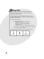
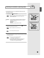
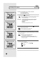
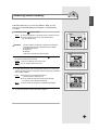
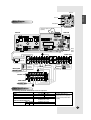
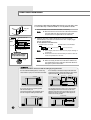
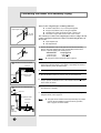
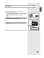
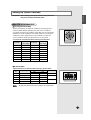
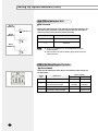
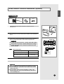
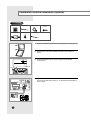
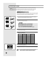
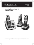
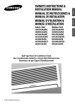
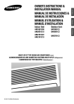
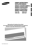
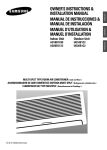
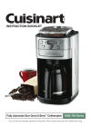
1
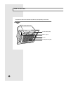
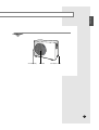
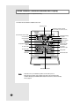
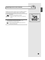
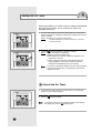
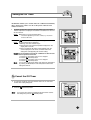
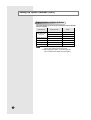
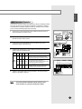
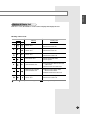
Indoor Unit
Outdoor Unit
ACC2400C
ACC2800C
UCC2400C
UCC2800C
Cassette-type Air Conditioner (Cool)
Aire acondicionador Tipo Casete (Refrigeración)
Climatiseur de type Cassette (Refroidissement)
E S F DB68-02173A(2)
ENGLISH
OWNER’S INSTRUCTIONS &
INSTALLATION MANUAL
MANUAL DE INSTRUCCIONES &
MANUAL DE INSTALACIÓN
MANUEL D’UTILISATION &
MANUEL D’INSTALLATION
Before Starting
The wired remote controller, wireless remote controller and Centralized controller of the
air conditioner are optional accessories. And your Owner’s Instructions is for all of them.
So that before using this instruction, ensure your option(s).
Safety Precautions
WARNING
DANGER
CAUTION
E-2
◆ If the power supply cord of this air conditioner is damaged,
it must be replaced by the manufacturer or its authorized
service personnel only in order to avoid a safety hazard.
◆ Do not attempt to install this air conditioner by yourself.
◆ This unit contains no user-serviceable parts. Always consult authorized
service personnel for repairs.
◆ When moving, consult authorized service personnel for disconnection
and installation of the unit.
◆ Do not become over-exposed to cold air by staying in the direct path of
the airflow of the air conditioner for extended periods of time.
◆ Do not insert fingers or objects into the outlet port or intake grilles.
◆ Do not start and stop air conditioner operation by disconnecting the
power supply cord and so on.
◆ Take care not to damage the power supply cord.
◆ In the event of a malfunction (burning smell, etc.), immediately stop
operation, turn off the electrical breaker, and consult authorized
service personnel.
◆ Provide occasional ventilation during use.
◆ Do not direct air flow at fireplaces or heating apparatus.
◆ Do not climb on, or place objects on, the air conditioner.
◆ Do not hang objects from the indoor unit.
◆ Do not set flower vases or water containers on top of air conditioners.
◆ Do not expose the air conditioner directly to water.
◆ Do not operate the air conditioner with wet hands.
◆ Do not pull power supply cord.
◆ Turn off power source when not using the unit for extended periods.
◆ Check the condition of the installation stand for damage.
◆ Do not place animals or plants in the direct path of the air flow.
◆ Do not drink the water drained from the air conditioner.
◆ Do not use in applications involving the storage of foods, plants or
animals, precision equipment, or art works.
◆ Do not apply any heavy pressure to radiator fins.
◆ Operate only with air filters installed.
◆ Do not block or cover the intake grille and outlet port.
◆ Ensure that any electronic equipment is at least one metre away from
either the indoor or outdoor units.
◆ Avoid installing the air conditioner near a fireplace or other heating
apparatus.
◆ When installing the indoor and outdoor unit, take precautions to prevent
access to infants.
◆ Do not use inflammable gases near the air conditioner.
ENGLISH
Contents
◆ PREPARING YOUR AIR CONDITIONER
■ Before Starting . . . . . . . . . . . . . . . . . . . . . . . . . . . . . . . . . . . . . .2
■ Safety Precautions . . . . . . . . . . . . . . . . . . . . . . . . . . . . . . . . . . .2
■ View of the Unit . . . . . . . . . . . . . . . . . . . . . . . . . . . . . . . . . . . . . .4
■ Wired Remote Controller-Buttons and Display . . . . . . . . . . . . . .6
■ Wireless Remote Controller-Buttons and Display . . . . . . . . . . . .7
■ Centralized Controller . . . . . . . . . . . . . . . . . . . . . . . . . . . . . . . . .8
■ The Indicators on the Unit (For Wireless Remote Controller Only) . . . . . .9
■ Getting Start . . . . . . . . . . . . . . . . . . . . . . . . . . . . . . . . . . . . . . .10
■ Inserting the Wireless Remote Controller Batteries . . . . . . . . . .11
USING WIRED REMOTE CONTROLLER
◆ OPERATING YOUR AIR CONDITIONER
■ Selecting the Automatic Operating Mode . . . . . . . . . . . . . . . . .13
■ Cooling Your Room . . . . . . . . . . . . . . . . . . . . . . . . . . . . . . . . . .14
■ Removing Excess Humidity . . . . . . . . . . . . . . . . . . . . . . . . . . .15
■ Airing Your Room . . . . . . . . . . . . . . . . . . . . . . . . . . . . . . . . . . .16
■ Adjusting the Air Flow Direction . . . . . . . . . . . . . . . . . . . . . . . .17
◆ PROGRAMMING YOUR AIR CONDITIONER
■ Setting the On Timer . . . . . . . . . . . . . . . . . . . . . . . . . . . . . . . . .18
■ Setting the Off Timer . . . . . . . . . . . . . . . . . . . . . . . . . . . . . . . . .19
USING WIRELESS REMOTE CONTROLLER
◆ OPERATING YOUR AIR CONDITIONER
■ Selecting the Automatic Operating Mode . . . . . . . . . . . . . . . . .21
■ Cooling Your Room . . . . . . . . . . . . . . . . . . . . . . . . . . . . . . . . . .22
■ Removing Excess Humidity . . . . . . . . . . . . . . . . . . . . . . . . . . .23
■ Airing Your Room . . . . . . . . . . . . . . . . . . . . . . . . . . . . . . . . . . .24
■ Adjusting the Air Flow Direction . . . . . . . . . . . . . . . . . . . . . . . . .25
◆ PROGRAMMING YOUR AIR CONDITIONER
■ Setting the On Timer . . . . . . . . . . . . . . . . . . . . . . . . . . . . . . . . .26
■ Setting the Off Timer . . . . . . . . . . . . . . . . . . . . . . . . . . . . . . . . .27
USING CENTRALIZED CONTROLLER
■
Using the Centralized Controller . . . . . . . . . . . . . . . . . . . . . . . .28
◆ RECOMMENDATIONS FOR USE
■ Operating Recommendations . . . . . . . . . . . . . . . . . . . . . . . . . .29
■ Temperature and Humidity Ranges . . . . . . . . . . . . . . . . . . . . . .29
■ Cleaning Your Air Conditioner . . . . . . . . . . . . . . . . . . . . . . . . . .30
■ Bio-Pure Filter Installation(Optional) . . . . . . . . . . . . . . . . . . . . .31
■ Solving Common Problems . . . . . . . . . . . . . . . . . . . . . . . . . . .32
◆ SPECIFICATIONS . . . . . . . . . . . . . . . . . . . . . . . . . . . . . . . . . . . . . .33
◆ INSTALLATION MANUAL . . . . . . . . . . . . . . . . . . . . . . . . . . . . . . . . .34
E-3
View of the Unit
The figures are shown in this instruction may differ from yours depending on the model.
Indoor Unit
Air flow blades(outlet)
Refer to page 9
Air inlet
Air filter(under the grille)
E-4
ENGLISH
Outdoor Unit
Air inlet(Rear)
Air outlet
Connection valve
E-5
Wired Remote Controller-Buttons and Display
The wired remote controller is an optional accessory.
The wired remote controller is installed on the wall.
Operating mode
Centralized controller indicator
(In case of installing the Centralized controller)
Communication error indicator
On Timer setting
Temperature setting
Fan speed
Off Timer setting
Air flow direction
Test indicator
Filter Sign indicator
On/Off & Timer
Set/Cancel button
Temperature adjustment
buttons
On Timer button
On/Off indicator
Fan speed
adjustment button
Off Timer button
Swing button
Test button
Filter Reset button
Mode selection button
Note
E-6
- Test button is for your installation specialist. You must NOT press it.
- After cleaning the air filter, press the filter reset button. Then the wired remote
controller will display the FILTER SIGN indicator when the time to clean the air filter;
refer to page 30.
Wireless Remote Controller-Buttons and Display
ENGLISH
The wireless remote controller is an optional accessory.
Operating mode
Temperature setting
Mode selection button
Temperature adjustment
buttons
Filter Reset button
Fan speed
Air flow direction
Fan speed adjustment
button
Swing button
On Timer setting
On Timer button
Off Timer setting
Off Timer button
Battery discharge indicator
On/Off & Timer
Set/Cancel button
Note
After cleaning the air filter, press the filter reset button.
E-7
Centralized Controller
The centralized controller is an optional accessory.
The centralized controller is installed on the wall.
Operating lamp
All On button
All Off button
On/Off indicators
On/Off buttons
Index
Note
E-8
Operating lamp comes on when at least one air conditioner connected to the
centralized controller is operating.
The Indicators on the Unit
(For Wireless Remote Controller Only)
ENGLISH
The receiver & display unit is an optional accessory for the wireless remote controller.
Timer indicator
Remote control sensor
On/Off button
On/Off indicator
Filter Sign indicator
E-9
Getting Start
You have just purchased a cassette type air conditioner and it has been
installed by your installation specialist.
Your Owner’s Instructions contain much valuable information on using your
air conditioner. Please take the time to read them as they will help you take full
advantage of the unit’s features.
The booklet is organized as follows.
◆ The following figures are shown on pages from 4 to 9 :
- Indoor and outdoor units
- Wired remote controller (buttons and display)
- Wireless remote controller (buttons and display)
- Centralized controller
- The indicators on the unit (For wireless remote controller only)
◆ In the main part of the document, you will find a series of step-by-step
procedures for each function available.
The illustrations in the step-by-step procedures use three different symbols:
PRESS
E-10
PUSH
HOLD DOWN
ENGLISH
Inserting the Wireless Remote Controller Batteries
You must insert or replace the remote controller batteries when :
◆ You purchase the air conditioner
◆ The remote controller does not work correctly
Note
◆ Use two AAA, LR03 1.5V batteries.
◆ Do not use old batteries or different kinds of batteries together.
◆ Batteries may be completely discharged after 12 months, even
if they have not actually been used.
1
Push the battery cover on the rear of the remote controller with your
thumb in the direction of the arrow and remove it.
2
Insert the two batteries, taking care to respect the polarities :
◆ + on the battery with + on the remote controller.
◆ - on the battery with - on the remote controller.
3
Close the cover by sliding it back until it clicks into place.
E-11
U s i n g Wi re d
Remote
C o n t ro l l e r
This chapter indicates how to operate and program
your air conditioner with the wired remote controller.
The wired remote controller is an optional accessory.
E-12
ENGLISH
Selecting the Automatic Operating Mode
In the Automatic mode, the room temperature and the fan speed are
controlled automatically.
1
If necessary, press
(ON/OFF) button.
Result: : ◆ The On/Off indicator on the wired remote controller comes on.
◆ The air conditioner runs in the mode selected when
◆ the unit was last used.
IMPORTANT
The air conditioner is fitted with a protection mechanism to
prevent the unit from being damaged when it is started
immediately after being:
◆ Plugged in
◆ Stopped
lt will start up normally after three minutes.
2 To select the AUTO mode, press the Mode button until
is displayed
at the top of the wired remote controller.
Result: : ◆ The air conditioner runs in AUTO mode.
Note
3
You can change modes at any time.
To adjust the temperature, press the Temperature buttons one or more times
until the required temperature is displayed. Possible temperatures are between
65OF and 86OF inclusive.
Result:
◆ Each time you press Temperature buttons:
- The temperature is adjusted by 1OF.
◆ The air conditioner starts cooling, provided that the room
temperature is higher than the selected temperature:
- The quantity of air is adjusted automatically.
E-13
Cooling Your Room
You must select the COOL mode if you wish to adjust the :
◆ Cooling temperature
◆ Fan speed when cooling
1
If necessary, press
◆ The On/Off indicator on the wired remote controller comes on.
◆ The air conditioner runs in the mode selected when
◆ the unit was last used.
Result:
IMPORTANT
2
3
The air conditioner is fitted with a protection mechanism to
prevent the unit from being damaged when it is started
immediately after being:
◆ Plugged in
◆ Stopped
lt will start up normally after three minutes.
To select the COOL mode, press the Mode button until
the top of the wired remote controller.
Result:
◆ The air conditioner runs in COOL mode.
Note
You can change modes at any time.
is displayed at
To adjust the temperature, press the Temperature buttons one or more times
until the required temperature is displayed. Possible temperatures are between
65OF and 86OF inclusive.
Result:
4
(ON/OFF) button.
◆ Each time you press Temperature buttons:
- The temperature is adjusted by 1OF.
◆ The air conditioner starts cooling, provided that the room
◆ temperature is higher than the selected temperature ; the fan
◆ will, however, operate.
Select the fan speed by pressing the Fan button one or more times until
the intended value is displayed :
Automatic(rotated :
➔
➔
)
Low
Medium
High
5
E-14
To control the direction of the air flow, refer to page 17.
ENGLISH
Removing Excess Humidity
If the atmosphere in your room is very humid or damp, you can
remove excess humidity without lowering the room temperature
too much.
1
If necessary, press
◆ The On/Off indicator on the wired remote controller comes on.
◆ The air conditioner runs in the mode selected when
◆ the unit was last used.
Result:
IMPORTANT
2
Note
4
The air conditioner is fitted with a protection mechanism to
prevent the unit from being damaged when it is started
immediately after being:
◆ Plugged in
◆ Stopped
It will start up normally after three minutes.
To select the DRY mode, press the Mode button until
the top of the wired remote controller.
Result:
3
(ON/OFF) button.
is displayed at
◆ The air conditioner runs in DRY mode.
You can change modes at any time.
To adjust the temperature, press the Temperature buttons one or more times
until the required temperature is displayed. Possible temperatures are between
65OF and 86OF inclusive.
Result:
◆ Each time you press Temperature buttons:
- The temperature is adjusted by 1OF.
◆ The air conditioner starts removing the excess humidity.
The quantity of air is adjusted automatically.
Note
In the dry mode, the fan speed is controlled automatically.
To control the direction of the air flow, refer to page 17.
E-15
Airing Your Room
If the atmosphere in your room is stale, you can air it using the
FAN feature.
1
If necessary, press
Result:
(ON/OFF) button.
◆ The On/Off indicator on the wired remote controller comes on.
◆ The air conditioner runs in the mode selected when the unit
was last used.
2
To select the FAN mode, press the Mode button until
the top of the wired remote controller.
Result:
3
◆ The air conditioner runs in FAN mode.
Select the fan speed by pressing the Fan button one or more times until
the intended value is displayed:
Low
Medium
High
4
E-16
is displayed at
To control the direction of the air flow, refer to page 17.
ENGLISH
Adjusting the Air Flow Direction
Depending on the position of the indoor unit, you can adjust the position of
the air flow blades, thus increasing the efficiency of the air conditioner.
1
Press the Swing button.
Result: The blades are moving between up and down.
IMPORTANT
2
When the air conditioner is first turned on, the blades are
moved.
To stop the blades, press the Swing button again.
To set to the required position, press the Swing button again.
When the blades are in the required position.
Note
You can also adjust by the hands the blades which are not
operated by the Swing button.
E-17
Setting the On Timer
The On Timer enables you to switch on the air conditioner automatically
after a given period of time. You can set the period of time from
30 minutes to 24 hours.
1
To set the operating time, press the On Timer button one or more times
until the required time is displayed. Possible time is between 0.5 hour and
24 hours inclusive.
Result:
2
◆ Each time you press On Timer button:
- The time is adjusted by 0.5 hour to 5 hours, by 1 hour from
6 hours to 24 hours.
Press the
(Set/Cancel) button to complete the setting.
Result: ◆ The remaining time is displayed.
◆ Blinking of the timer indicator stops.
◆ The selected mode and the temperature disappear on the
display after 5 seconds.
◆ The air conditioner will switch on automatically when the
counter displayed on the remote controller reaches the
setting time as disappearing the On timer setting.
Note
You can see or change the setting mode and/or the temperature
by pressing the Mode button or the Temperature buttons after
setting the On timer.
To Cancel the On Timer
1
To cancel the On Timer, press the On Timer button one or more times
until the On timer setting disappears.
2
Press the
Note
E-18
(Set/Cancel) button.
If you want to turn on the air conditioner before the timer reaches
the setting time, press the (ON/OFF) button.
ENGLISH
Setting the Off Timer
The Off Timer enables you to switch off the air conditioner automatically
after a given period of time. You can set the period of time from 30
minutes to 24 hours.
1
To set the operating time, press the Off Timer button one or more times
until the required time is displayed. Possible time is between 0.5 hour and
24 hour inclusive.
Result:
2
◆ Each time you press Off Timer button:
- The time is adjusted by 0.5 hour to 5 hours, by 1 hour from
6 hours to 24 hours.
Press the
(Set/Cancel) button to complete the setting.
Result: ◆ The remaining time is displayed.
◆ Blinking of the timer indicator stops.
◆ The selected mode and the temperature disappear on the
display after 5 seconds.
◆ The air conditioner will switch off automatically when the
counter displayed on the remote controller reaches the
setting time as disappearing the Off timer setting.
Example If you would like to turn the air conditioner on after 2 hours
and to operate it for 2 hours:
1. Press the On Timer button until ‘2.0 Hr’ is displayed.
2. Press the
(Set/Cancel) button.
3. Press the Off Timer button until ‘4.0 Hr’ is displayed.
4. Press the
(Set/Cancel) button.
Note
You can see or change the setting mode and/or the temperature
by pressing the Mode button or the Temperature buttons after
setting the Off timer.
To Cancel the Off Timer
1
To cancel the Off Timer, press the Off Timer button one or more times
until the timer setting disappears.
2
Press the
Note
(Set/Cancel) button.
If you want to turn off the air conditioner before the timer reaches
the setting time, press the (ON/OFF) button.
E-19
Using
W i re l e s s
Remote
C o n t ro l l e r
This chapter indicates how to operate and program
your air conditioner with the wireless remote controller.
The wireless remote controller is an optional accessory.
E-20
ENGLISH
Selecting the Automatic Operation Mode
In the Automatic mode, the room temperature and the fan speed are
controlled automatically.
1
If necessary, press
(ON/OFF) button.
Result: : ◆ The On/Off indicator on the unit comes on.
◆ The air conditioner runs in the mode selected when
the unit was last used.
◆ The indoor unit beeps.
IMPORTANT
The air conditioner is fitted with a protection mechanism to
prevent the unit from being damaged when it is started
immediately after being:
◆ Plugged in
◆ Stopped
lt will start up normally after three minutes.
2 To select the AUTO mode, press the Mode button until
is displayed
at the top of the wireless remote controller.
Result: : ◆ The indoor unit beeps.
◆ The air conditioner runs in AUTO mode.
Note
3
You can change modes at any time.
To adjust the temperature, press the Temperature buttons one or more times
until the required temperature is displayed. Possible temperatures are between
65OF and 86OF inclusive.
Result:
◆ Each time you press Temperature buttons:
- The temperature is adjusted by 1OF.
◆ The air conditioner starts cooling, provided that the room
temperature is higher than the selected temperature:
The quantity of air is adjusted automatically.
E-21
Cooling Your Room
You must select the COOL mode if you wish to adjust the :
◆ Cooling temperature
◆ Fan speed when cooling
1
If necessary, press
Result:
IMPORTANT
2
3
◆ The On/Off indicator on the unit comes on.
◆ The air conditioner runs in the mode selected when the
unit was last used.
◆ The indoor unit beeps.
The air conditioner is fitted with a protection mechanism to
prevent the unit from being damaged when it is started
immediately after being:
◆ Plugged in
◆ Stopped
lt will start up normally after three minutes.
To select the COOL mode, press the Mode button until
at the top of the wireless remote controller.
Result:
◆ The indoor unit beeps.
◆ The air conditioner runs in COOL mode.
Note
You can change modes at any time.
◆ Each time you press Temperature buttons:
- The temperature is adjusted by 1OF.
- The indoor unit beeps.
◆ The air conditioner starts cooling, provided that the room
◆ temperature is higher than the selected temperature ; the fan
◆ will, however, operate.
Select the fan speed by pressing the Fan button one or more times until
the intended value is displayed :
Automatic(rotated :
➔
➔
)
Low
Medium
High
5
E-22
is displayed
To adjust the temperature, press the Temperature buttons one or more
times until the required temperature is displayed. Possible temperatures
are between 65OF and 86OF inclusive.
Result:
4
(ON/OFF) button.
To control the direction of the air flow, refer to page 25.
ENGLISH
Removing Excess Humidity
If the atmosphere in your room is very humid or damp, you can
remove excess humidity without lowering the room temperature
too much.
1
If necessary, press
Result:
IMPORTANT
2
3
4
◆
◆
◆
◆
(ON/OFF) button.
The On/Off indicator on the unit comes on.
The air conditioner runs in the mode selected when
the unit was last used.
The indoor unit beeps.
The air conditioner is fitted with a protection mechanism to
prevent the unit from being damaged when it is started
immediately after being:
◆ Plugged in
◆ Stopped
lt will start up normally after three minutes.
To select the DRY mode, press the Mode button until
at the top of the wireless remote controller.
Result:
◆ The indoor unit beeps.
◆ The air conditioner runs in DRY mode.
Note
You can change modes at any time.
is displayed
To adjust the temperature, press the Temperature buttons one or more
times until the required temperature is displayed. Possible temperatures
are between 65OF and 86OF inclusive.
Result:
◆ Each time you press Temperature buttons:
- The temperature is adjusted by 1OF.
- The indoor unit beeps.
◆ The air conditioner starts removing the excess humidity.
The quantity of air is adjusted automatically.
Note
In the dry mode, the fan speed is controlled automatically.
To control the direction of the air flow, refer to page 25.
E-23
Airing Your Room
If the atmosphere in your room is stale, you can air it using the
FAN feature.
1
If necessary, press
Result:
2
◆ The On/Off indicator on the unit comes on.
◆ The air conditioner runs in the mode selected when
◆ the unit was last used.
◆ The indoor unit beeps.
To select the FAN mode, press the Mode button until
the top of the wireless remote controller.
Result:
Result:
Note
3
(ON/OFF) button.
◆ The indoor unit beeps.
◆ The air conditioner runs in FAN mode.
You can change modes at any time.
Select the fan speed by pressing the Fan button one or more times until
the intended value is displayed:
Low
Medium
High
4
E-24
is displayed at
To control the direction of the air flow, refer to page 25.
ENGLISH
Adjusting the Air Flow Direction
Depending on the position of the indoor unit, you can adjust the position of
the air flow blades, thus increasing the efficiency of the air conditioner.
1
Press the Swing button.
◆ The blades are moving between up and down.
◆ The indoor unit beeps.
Result:
Result:
IMPORTANT
2
When the air conditioner is first turned on, the blades are moved.
To stop the blades, press the Swing button again.
To set to the required position, press the Swing button again.
When the blades are in the required position.
Note
You can also adjust by the hands the blades which are not
operated by the swing button.
E-25
Setting the On Timer
The On Timer enables you to switch on the air conditioner automatically
after a given period of time. You can set the period of time from 30
minutes to 24 hours.
1
To set the operating time, press the On Timer button one or more times
until the required time is displayed. Possible time is between 0.5 hour and
24 hour inclusive.
Result:
2
◆ Each time you press On Timer button:
- The time is adjusted by 0.5 hour to 5 hours, by 1 hour from
6 hours to 24 hours.
Press the
(Set/Cancel) button to complete the setting.
Result: ◆ The remaining time is displayed.
◆ Blinking of the timer indicator stops.
◆ The selected mode and the temperature disappear on the
display after 5 seconds.
◆ The air conditioner will switch on automatically when the
counter displayed on the remote controller reaches the
setting time as disappearing the On timer setting.
Note
You can see or change the setting mode and/or the temperature
by pressing the Mode button or the Temperature buttons after
setting the On timer.
To Cancel the On Timer
1
To cancel the On Timer, press the On Timer button one or more times
until the timer setting disappears.
2
Press the
Note
E-26
(Set/Cancel) button.
If you want to turn on the air conditioner before the timer reaches
the setting time, press the
(ON/OFF) button.
ENGLISH
Setting the Off Timer
The Off Timer enables you to switch off the air conditioner automatically
after a given period of time. You can set the period of time from 30
minutes to 24 hours.
1
To set the operating time, press the Off Timer button one or more times
until the required time is displayed. Possible time is between 0.5 hour and
24 hour inclusive.
Result:
2
◆ Each time you press Off Timer button:
- The time is adjusted by 0.5 hour to 5 hours, by 1 hour from
6 hours to 24 hours.
Press the
(Set/Cancel) button to complete the setting.
Result: ◆ The remaining time is displayed.
◆ Blinking of the timer indicator stops.
◆ The selected mode and the temperature disappear on the
display after 5 seconds.
◆ The air conditioner will switch off automatically when the
counter displayed on the remote controller reaches the
setting time as disappearing the Off timer setting.
Example If you would like to turn the air conditioner on after 2 hours
and to operate it for 2 hours:
1. Press the On Timer button until ‘2.0 Hr’ is displayed.
2. Press the
(Set/Cancel) button.
3. Press the Off Timer button until ‘4.0 Hr’ is displayed.
4. Press the
(Set/Cancel) button.
Note
You can see or change the setting mode and/or the temperature
by pressing the Mode button or the Temperature buttons after
setting the Off timer.
To Cancel the Off Timer
1
To cancel the Off Timer, press the Off Timer button one or more times
until the timer setting disappears.
2
Press the
Note
(Set/Cancel) button.
If you want to turn off the air conditioner before the timer reaches
the setting time, press the
(ON/OFF) button.
E-27
Using the Centralized Controller
The centralized controller is an optional accessory.
Up to sixteen air conditioners can be turned on or off by connecting to the
centralized controller. However, you cannot adjust the cooling temperature
or set the timer with it. If you also have the wired remote controller,
CENTRALIZED CONTROL is displayed at the top of the remote controller.
1
To turn on the all of air conditioners connected to the centralized controller,
press the
(All ON) button.
2
To turn on/off a specific air conditioner, press the
Result:
3
E-28
(ON/OFF) button.
◆ The On/Off indicator comes on when the air conditioner is
operating.
To turn off the all of air conditioners connected to the centralized controller,
press the
(All OFF) button.
ENGLISH
Operating Recommendations
Here are a few recommendations that you should follow when operating
your air conditioner.
Topic
Recommendation
Power failure
If a power failure occurs while the air conditioner is operating,
the unit will be switched off. When the power returns, the air
conditioner restarts in the previous operation mode.
Temperature and Humidity Ranges
The following table indicates the temperature and humidity ranges,
within which the air conditioner can be used.
If the air conditioner is used at...
Then...
High temperature
The automatic protection feature may be
triggered and the air conditioner stopped.
Low temperature
A water leakage or some other
malfunction may happen if the heat
exchanger freezes.
High humidity levels
Water may condense on and drip from
the surface of the indoor unit if it is used
for a long periods.
Mode
Outdoor Temperature
Indoor Temperature
Cooling
23°F to 109°F approx.
70°F to 90°F approx.
Drying
70°F to 109°F approx.
70°F to 90°F approx.
❇
Indoor Humidity
80% or less
-
If the cooling operation is used at over 91°F(indoor temperature)
then, does not a full capacity.
E-29
Cleaning Your Air Conditioner
To get the best possible use out of your air conditioner, you must clean
it regularly to remove the dust that accumulates on the air filter.
IMPORTANT
1
Open the front grille by pushing the tabs on the grille.
IMPORTANT
2
Before cleaning your air conditioner, ensure that you have
switched off the electric circuit breaker used for the unit.
You must give attention when disassembling the front
grille and must check the safety clips have been
installed. If you do not check them, the front grille will
drop suddenly and you will be hurt.
Remove the front grille.
2-1 Remove the safety clips.
2-2 Open the front grille about 45° and pull it forward.
Safety Clip
3
Pull out the air filter.
4
Remove all dust on air filter with a vacuum cleaner or a brush. In case of
serious dust accumulation, put the air filter in warm detergent water and
shake it vertically.
Note
5
Dry the air filter.
6
When you have finished, insert the filter into the front grille.
7
Clean the unit with a vacuum cleaner or a brush once a month.
8
Reinstall the front grille and the safety clips.
Note
Note
Wired Remote Controller
E-30
When you have installed the Bio-Pure filter, do not allow
any liquids to contact the filter. It may lose its properties.
Wireless Remote Controller
You can use all 4 points of the indoor unit for installing the front
grille and the safety clips depending on your requirement.
After cleaning the air conditioner, press the Filter Reset button.
ENGLISH
Bio-Pure Filter Installation (Optional)
The air conditioner can be fitted with a Bio-Pure filter to remove minute dust
particles. The service life of the filter is approximately three months
depending on the time during which the air conditioner is used.
1
Remove the vinyl packing from the filter.
Note
Do not remove the packing from a bio-pure filter until you wish
to use the filter, as it will lose its properties.
2
Open the front grille by pulling the tabs on the grille.
3
Remove the front grille.
3-1 Remove the safety clips.
3-2 Open the front grille about 45° and pull it forward.
4
Pull out the air filter.
5
Locate the bio-pure filter on the center of air filter.
6
Secure the bio-pure filter with four screws.
7
Reinstall the air filter, the front grille and the safety clips.
E-31
Solving Common Problems
Before contacting the after-sales service, perform the following simple
checks. They may save your time and expense of an unnecessary call.
Problem
Explanation/Solution
The air conditioner does not ◆ Check that the breaker used for the air conditioner is switched on.
operate at all
Wired Remote Controller
The air conditioner does not ◆
is displayed on the wired remote controller. In this case,
operate with the remote
turn the air conditioner off and contact your dealer.
controller
Wired Remote Controller
When turning on/off the
air conditioner, it is not
turned on/off immediately.
◆ In case of using the wired remote controller for a group, the air
conditioners connected to the remote controller are turned on/off in
order. Thus, it takes some time(up to 32 seconds).
Wireless Remote Controller
The air conditioner does not ◆ Check that there are no obstacles between you and the remote
operate with the remote
control sensor.
controller
◆ Check the wireless remote controller batteries (Refer to page 11).
◆ Check that you are close enough to the remote control sensor.
(seven metres/yards/23ft or less).
Wireless Remote Controller
No beep is heard when you ◆ Check that you are pointing the remote controller at the remote
control sensor of the receiver & display unit.
press
(ON/OFF) on the
remote controller
◆ Replace the remote controller batteries if necessary.
◆ If there is a strong light around the air conditioner, a
three-wavelength light, a neon sign, etc., for example, the air
conditioner may not be operated with a remote controller. If this
happens, use the remote controller close by the remote control
sensor.
The air conditioner does
not cool
◆ Check that the correct operating mode has been selected.
◆ The room temperature may be too low or too high.
◆ Dust may be blocking the air filter guard; refer to page 30
for cleaning instructions.
◆ Check that there is no obstacle in front of the outdoor unit.
E-32
ENGLISH
Specifications
MODEL
Performance
Ratings
Refrigeration
Lines
Dimensions
& Weight
ACC2800C
23000
28000
10.0
10.0
Btu/h
Capacity Cooling
SEER
Moisture Removal
Pts/h
5
6
Air FLOW(Cooling, HIGH)
CFM
565
600
dB
46/58
49/61
Power source
∅,V, Hz
1∅, 208-230V~, 60Hz
1∅, 208-230V~, 60Hz
Min.Ampacity
A
12.0
13.0
Cooling Watts
W
2400
2800
Flare
Flare
Sound Rating-(In/Out)
Electrical
Data
ACC2400C
Connections
Liquid Line O. D.
in
1/4
1/4
Suction Line O.D.
in
5/8
5/8
Factory Pre-charge
ft
16
16
Max. Line length
ft
100
100
Max. Height Difference
ft
50
50
ACC2400C
INDOOR UNIT
WXHXD
in
33 x 9 x 33
Net Weight
Ibs
64
1
16
OUTDOOR UNIT
1
16
33161 x 9 161 x 33161
68
UCC2400C
WXHXD
in
34 x 25 x 12
Net Weight
Ibs
145
✳ Standard rating conditions
ACC2800C
1
16
5
8
Cooling
1
8
UCC2800C
34 85 x 31 18 x 12163
3
16
168
Outdoor
Indoor
DB
WB
DB
WB
°F
80
67
95
75
°C
26.7
19.4
35.0
23.9
E-33
INSTALLATION
MANUAL
Indoor Unit Dimensions
Unit : mm(inch)
Water Supply Intake
1
699(27 2 )
1
840(33 16 )
(Outer Dimensions)
1
1
25 (1)
9
90(316 )
5
110(416 )
1
230(916 )
7
290(11 16 )
260(10 4 )
(Cutting Dimension of Ceiling)
)
Dimensions)
(Space of Suspension Bolts)
(Space of Suspension Bolts)
766(30 16 )
E-34
156(6 8 )
11
246(916 )
1
3
(Dimensions of Front Panel)
(Cutting Dimensions of Ceiling)
5
880(34 8
)
840(33 16 ) (Outer
5
880(34 8
3
15
126(416 )
11
145 (516 )
3
950(37 8 )
146(5 4 )
Gas refrigerant port
Fixing bracket
Drain tube outlet
7
200 (7 8 )
Liquid refrigerant port
ENGLISH
Contents
◆ PREPARING THE INSTALLATION
■ Deciding on Where to Install the Air Conditioner . . . . . . . . . . . .36
■ Air Conditioner and Accessories . . . . . . . . . . . . . . . . . . . . . . . .38
◆ INSTALLING THE INDOOR UNIT
■ Indoor Unit Installation . . . . . . . . . . . . . . . . . . . . . . . . . . . . . . . .39
■ Purging the Unit . . . . . . . . . . . . . . . . . . . . . . . . . . . . . . . . . . . .40
■ Connecting the Connection Cord . . . . . . . . . . . . . . . . . . . . . . .40
■ Drain Hose Installation . . . . . . . . . . . . . . . . . . . . . . . . . . . . . . .42
■ Connecting the Indoor Unit Assembly Piping . . . . . . . . . . . . . .44
■ Cutting/Flaring the Pipes . . . . . . . . . . . . . . . . . . . . . . . . . . . . . .45
◆ INSTALLING THE OUTDOOR UNIT
■ Connecting the Cables to the Outdoor Unit . . . . . . . . . . . . . . .46
■ Checking Correct Grounding . . . . . . . . . . . . . . . . . . . . . . . . . . .47
■ Fixing the Unit in Position . . . . . . . . . . . . . . . . . . . . . . . . . . . . .48
◆ COMPLETING THE INSTALLATION
■ Connecting Up and Removing Air in the Circuit . . . . . . . . . . . .49
■ Performing Leak Tests . . . . . . . . . . . . . . . . . . . . . . . . . . . . . . . .50
■ Insulation . . . . . . . . . . . . . . . . . . . . . . . . . . . . . . . . . . . . . . . . . .51
■ Installing the Front Panel . . . . . . . . . . . . . . . . . . . . . . . . . . . . . .52
◆ INSTALLING THE OPTIONAL ACCESSORIES
■ Setting up Option Switches . . . . . . . . . . . . . . . . . . . . . . . . . . . .53
■ Wired remote controller Installation (Optional) . . . . . . . . . . . . .57
■ Centralized controller Installation (Optional) . . . . . . . . . . . . . . .58
■ Receiver & display unit Installation (Optional) . . . . . . . . . . . . . .60
■ Bio-Pure Filter Installation (Optional) . . . . . . . . . . . . . . . . . . . . .61
◆ OTHERS
■ Controlling a Group . . . . . . . . . . . . . . . . . . . . . . . . . . . . . . . . . .62
■ Checking and Testing Operations . . . . . . . . . . . . . . . . . . . . . . .64
■ Troubleshooting . . . . . . . . . . . . . . . . . . . . . . . . . . . . . . . . . . . . .66
■ Explaining Operations to the Owner . . . . . . . . . . . . . . . . . . . . .68
E-35
Deciding on Where to Install the Air Conditioner
When deciding on the location of the air conditioner with the owner, the following restrictions
must be taken into account.
General
Do NOT install the air conditioner in a location where it will come into contact with the following elements:
◆ Combustible gases
◆ Saline air
◆ Machine oil
◆ Sulphide gas
◆ Special environmental conditions
If you must install the unit in such conditions, first consult your dealer.
Indoor Unit
◆ There must be no obstacles near the air inlet and outlet.
◆ Choose a space of ceiling that enables the pipes and cables to be easily connected to the outdoor unit and
the recommended length of 5m/16ft 5in to be respected (“L” m/ft maximum-“L”:indicated in the diagram on the
page opposite). Proper drain hose passage should also be considered.
◆ Install the indoor unit on a ceiling that can support its weight.
◆ Maintain sufficient clearance around the indoor unit, as indicated in the diagram on the page opposite.
◆ Make sure that the water dripping from the drain hose runs away correctly and safely.
Outdoor Unit
◆ The outdoor unit must NEVER be placed on its side or upside down, as the compressor lubrication oil will run
into the cooling circuit and seriously damage the unit.
◆ Choose a location that is dry and sunny, but not exposed to direct sunlight or strong winds.
◆ Do not block any passageways or thoroughfares.
◆ Choose a location where the noise of the air conditioner when running and the discharged air do not disturb
any neighbours.
◆ Choose a position that enables the pipes and cables to be easily connected to the indoor unit. Recommended
length between indoor and outdoor unit is 5m/16ft 5in (“L” m/ft maximum).
◆ Install the outdoor unit on a flat, stable surface that can support its weight and does not generate any
unnecessary noise and vibration.
◆ Position the outdoor unit so that the air flow is directed towards the open area.
◆ Maintain sufficient clearance around the outdoor unit, as indicated in the diagram on the page opposite.
◆ If the outdoor unit is installed at a height, ensure that its base is firmly fixed in position; the maximum height
difference between indoor and outdoor unit is “H” m/ft (“H” indicated in the diagram on the page opposite.).
◆ Make sure that the water dripping from the drain hose runs away correctly and safely.
CAUTION
◆ You have just purchased a cassette-type air conditioner and it has to be
installed by your installation specialist.
◆ This device must be installed according to the national electrical rules.
E-36
ENGLISH
Respect the clearances and maximum lengths indicated in the diagram below when installing the unit.
Liquid Refrigerant tube
Gas Refrigerant tube
“H” m/ft maximum
Model
300mm(12inc
h)
minimum
L
h)
inc
12
(
m
0m um
30 inim
m
350mm
(14inch)
minimum
✴ The appearance of the outdoor unit
h)
inc
12 m
(
m u
0m im
30 min
may be different from the diagram
depending on the model.
Unit : mm(inch)
1500mm(5ft)
minimum
230mm(3/4ft)
255 (10)
Space requirement when installing the indoor unit
11
17 ( 16 )
13
1000mm(3ft) minimum
H
✴✴24✴✴ 30m/ 15m/
✴✴28✴✴ 100ft 50ft
Drain hose
20 ( 16 )
E-37
Air Conditioner and Accessories
The following accessories are supplied with the air conditioner. The quantities are indicated in parentheses.
Basic Accessories
Owner’s Instructions &
Installation Manual (1)
Pattern Sheet(1)
Insulation
Cover Drain(1)
Insulation
Cover Pipe(2)
Insulation
Cover Band(1)
Insulation Pipe 5/8"(1)
Insulation Drain
Pipe(1)
Cable-Tie(5)
Flexible Hose(1)
TH M4 X 12 Tapped
Screw(4)
Pad Stopper(1)
Insulation Drain Sub (1)
Bolt(4)
<Front Panel>
Flare Nuts 1/4 (1)
Flare Nuts 5/8 (1)
Rubber Leg (4)
S
OWNER'S INSTRUCTION
INSTRUCCIONES
MANUAL DE L'USO
PER
ISTRUZIONIINSTRUÇÕES
MANUAL DE
N
MANUEL D'UTILISATIO
ANWEISUNG
GEBRAUCHS
Air ConditionerSplit
Splut-type Room
doméstico sistema
ad unità Separate
Aire acondicionado
d'aria per ambienti
Condizionatorede ar condicionado tipo Split
Aparelho
type séparé
Climatiseur de
Geteilte raumklimaanlage
Optional Accessories
Wired Remote
Controller(1)
Cable-Tie(2)
Cable Clamp(5)
TH M4 X 16 Tapped
Screw(7)
Battery(2)
FH M4 X 16 Tapped
Screw(2)
Remote Controller
Holder(1)
Centralized Controller(1)
Cable-Tie(2)
Cable Clamp(5)
TH M4 X 16 Tapped
Screw(7)
Transmitter(1)
Spacer Support(4)
Cable-Tie(2)
Bio-Pure Filter(1)
TH M4 X 10 Tapped
Screw(4)
Air blocking Kit(1)
Wireless Remote
Controller(1)
Note
E-38
Receiver & Display
Unit(1)
◆ Refrigeration pipes and their insulating materials, power cables are not supplied.
ENGLISH
Indoor Unit Installation
1
Place the pattern sheet on the ceiling at the spot where you want to
install the indoor unit.
Note
◆ Since the diagram is made of paper, it may shrink or stretch
slightly due to temperature or humidity. For this reason,
before drilling the holes maintain the correct dimensions
between the markings; refer to page 34.
2
3
Install the suspension bolts depending on the ceiling type.
IMPORTANT Ensure that the ceiling is strong enough to support
the weight of the indoor unit.
Before hanging the unit, test the strength of each
attached suspension bolt.
4
Concrete
Insert bolt anchors, use existing ceiling supports or construct a suitable
support as shown in figure.
Insert
Hole in anchor
Hole in plug
Suspension bolt(M8)-field supply
Ceiling support
Screw eight nuts to the suspension bolts making space for hanging
the indoor unit.
IMPORTANT You must install the suspension bolts more than four
when installing the indoor unit.
5
Hang the indoor unit to the suspension bolts between two nuts.
Note
◆ Tubing must be laid and connected inside the ceiling when
suspending the unit. If the ceiling is already constructed, lay
the tubing into position for connection to the unit before
placing the unit inside the ceiling.
6
Screw the nuts to suspend the unit. Cut a pad stopper and place it on the
bracket at this time.
7
Adjust the unit to the appropriate position considering the installation area for the front
panel.
7-1 Place the pattern sheet on the indoor unit.
7-2 Adjust a space between the ceiling and the indoor unit by using the gauge
of dimensions.
7-3 Fix the indoor unit securely after adjusting level of the unit by using a leveler.
7-4 Remove the pattern sheet, connect the other cables and install the front panel.
Pad stopper
Bracket
Unit:mm(inch)
13
Indoor Unit
11
20 ( 16 )
Ceiling
17 ( 16 )
Gauge of
Dimensions
E-39
Purging the Unit
On delivery, the indoor unit is loaded with an inert nitrogen gas.
All this gas must therefore be purged before connecting the assembly
piping. To purge the inert gas, proceed as follows.
Unscrew the caps at the end of each pipe.
Result:
Note
All inert gas escapes from the indoor unit.
◆ To prevent dirt or foreign objects from getting into the pipes
during installation, do NOT remove the caps completely until
you are ready to connect the piping.
Connecting the Connection Cord
The indoor unit is powered from the outdoor unit via the connection cord.
1
Remove the screws on the electrical component box and remove the
cover plates.
2
Route the connection cord through the conduit hole of side of the indoor
unit and connect the cable to terminals as shown in page 41.
3
Route the other end of the cable to the outdoor unit through the ceiling &
the hole on the wall.
4
Reassemble the electrical component box cover, carefully tightening the
screws.
5
For further details on how to plug the other end of the connection cord
into the outdoor unit, refer to page 46.
Cable Clamp
E-40
ENGLISH
Main PCB
Sub PCB
Wiring Diagram
Terminal block
Receiver & Display Unit
(Optional)
SUB PCB
MAIN PCB
CN9
CN7
SW1
SW2
CN20 Connector
DIP Switch
Rotary
Digital
Switch
Indoor Unit
Transmitter
(Optional)
Centralized
Controller
(Optional)
MAIN POWER
Ventilator
Motor
Communication
Float
Switch
Power
EARTH
Wired
Remote
Controller
(Optional)
208-230V~, 60Hz
Outdoor Unit
MAIN POWER
208-230V~, 60Hz
Cable Specifications
The following electrical characteristics must be respected.
MODEL
Power
Sub switch
Fuse
Min. size of electric Wires
from/to the indoor/outdoor unit
Size of electric input wires
20m(6
9
16
ft) or less
3
8
50m(16 ft) or less
ACC2400C
ACC2800C
1Ø - 208-230V~, 60Hz
25A
30A
25A
30A
H07RN-F, 4G, 1.0mm2
Note
The power cables are not
supplied with the air conditioner.
The user should purchase them
separately.
H07RN-F, 3G, 2.5mm2
H07RN-F, 3G, 4.0mm2
E-41
Drain Hose Installation
Care must be taken when installing the drain hose for the indoor unit
to ensure that any condensate water is correctly drained outside.
Drain tube
outlet
1
Insert the flexible hose to the drain tube outlet, if necessary.
Note
Insulation drain sub
Indoor
Unit
2
Band(Not supplied)
◆ Attach the drain hose to the drain tube outlet with the adhesives
to prevent water leaks, then secure the hose with a band
etc..(The band is not supplied with the air conditioner.)
Install the drain hose so that its length can be as short as possible.
Internal diameter of the drain hose should be the same or slightly bigger
than the external diameter.
◆ Inner diameter of the drain hose
Flexible hose is connected
Flexible hose is not connected
Adhesives
32mm/1
Insulation drain pipe
Insulation cover drain
Note
CAUTION
Must fit tightly against
body without any gap.
No gap
3
1
4
inch(Outer diameter)
27mm/1inch(Outer diameter)
◆ Give a slightly slant to the drain hose for proper drainage of
condensate.
◆ Secure the drain hose with the band joint and the cable-tie
not to be separated from the unit.
Wrap the drain hose with the insulation drain as shown in figure and secure it.
Note
◆ When connecting the drain hose without the flexible hose,
you should attach it to the drain tube outlet with adhesives
and tapes to prevent water leaks.
CAUTION
Check that the indoor unit is level with the ceiling by using the leveler.
If it is necessary to increase the height of the drain hose
somewhat, the portion directly after 30cm/1ft. If it is raised
higher than 50cm/1 85 ft , there can be water leaks.
300mm (12")or less
1~1.5m (3~5ft)
5
550mm (1 8 ft) or less
Air bleeder
5
200mm ( 8 ft)
Band joint
Flexible hose
Ceiling
Do not give the hose and upward gradient
after the connection port.
This will cause water to flow backwards when
the unit is stopped, resulting in water leaks.
Ceiling
Do not apply force to the piping on the unit side when
connecting the drain hose. The hose should not be
allowed to hang loose from its connection to the unit.
Fasten the hose to a wall, frame or other support as
close to the unit as possible.
Support pieces
Upward gradient
1~1.5m(3~5ft)
1/100 or more
Ceiling
E-42
7
750mm (216 ft) or less
Do not install air bleeding tubes, as this may
cause water to spray from the drain tube outlet.
Ceiling
ENGLISH
Testing the drainage
You should test the drainage after completing the installation.
Prepare a little water about 2.0 liter.
1
Remove two screws on the cover drain pump and pull out the cover.
Cover drain pump
2
Pour water into the indoor unit as shown in figure.
Note
3
Confirm that the water flows out through the drain hose.
Note
4
◆ If you do not pour water inside the water supply intake,
water may spill from the indoor unit.
◆ You can check the drainage only when the air conditioner is
turned on.
Reassemble the cover drain pump and the screws.
E-43
Connecting the Indoor Unit Assembly Piping
There are two refrigerant pipes of differing diameters:
◆ A smaller one(6.35mm, 1/4") for the liquid refrigerant
Liquid refrigerant port
◆ A larger one(15.88mm, 5/8") for the gas refrigerant
◆ The thickness of tube should not less than 1.0mm(1/16").
A
Gas refrigerant port
◆ The inside of copper tube must be clean & has no dust.
The connection procedure for the refrigerant pipes varies according to the exit
position of the pipes from the indoor unit, as seen when facing the indoor in
the “A” side.
◆ Liquid refrigerant port
◆ Gas refrigerant port
1
Remove the protection caps on the pipes and connect the assembly
pipes to each pipe, tightening the nuts, first manually and then with a
wrench, a spanner applying the following torque.
Outer Diameter
6.35 mm (1/4")
15.88 mm (5/8")
Note
a. When the indoor unit is above the outdoor
unit
Oil trap(Must be installed
every 6m/20ft)
b. When the outdoor unit is above the indoor
unit
Outdoor unit
Oil trap(Must be installed
every 6m/20ft)
Indoor unit
Radius
5cm (2")
Oil trap
(suction tube)
E-44
◆ If the pipes must be shortened refer to page 45.
2
Must use insulator which is thick enough to cover the refrigerant tube to
protect the condensate water on the outside of pipe falling onto the floor
and the efficiency of the unit will be better.
3
Cut off any excess foam insulation.
4
Be sure that there must be no crack or wave on the bended area.
5
It would be necessary to double the insulation thickness(10mm/ 38 " or
more) to prevent condensation even on the insulator when if the installed
area is warm and humid.
6
Shape an oil trap as shown in figure. The oil trap must be formed every
level difference of 6m(20ft).
7
For further details on connecting up to the outdoor unit and purging the
refrigerant circuit, refer to page 49.
Indoor unit
Outdoor unit
Torque (kgf•cm)
160(11 35 ft•lb)
400(29 ft•lb)
Note
◆ The pipes will be insulated and fixed permanently into position
once the whole installation has been tested for gas leaks;
refer to page 53 for further details.
ENGLISH
Cutting/Flaring the Pipes
Connect the pipe within 30m(100ft) and cutting pieces will not be gone
into the pipe as being clean to pipe section.
1
Make sure that you have the required tools available (pipe cutter, reamer,
flaring tool and pipe holder).
2
If you wish to shorten the pipes, cut it with a pipe cutter, taking care to
ensure that the cut edge remains at a 90° angle with the side of the pipe.
Refer to the illustrations below for examples of edges cut correctly and
incorrectly.
O
90
Oblique
Rough
Burr
3
To prevent any gas from leaking out, remove all burrs at the cut edge of the
pipe, using a reamer.
4
Slide a flare nut on to the pipe and modify the flare.
Outer Diameter(D)
6.35 mm (1/4")
15.88 mm (5/8")
5
Depth (A)
1.3 mm(5/100")
2.2 mm(9/100")
Check that the flaring is correct, referring to the illustrations below for
examples of incorrect flaring.
Inclined
Damaged Surface
Cracked
Uneven Thickness
6
Align the pipes and tighten the flare nuts first manually and then with
a wrench, applying the following torque.
Outer Diameter
Torque(kgf•cm)
6.35 mm (1/4")
160(11 35 ft•lb)
15.88 mm (5/8")
400(29 ft•lb)
7
For further details on how to connect up to the outdoor unit and purge
the circuit, refer to page 49.
CAUTION
◆ In case of welding the pipe, you must weld with nitrogen
gas blowing.
E-45
Connecting the Cables to the Outdoor Unit
Two electric cables must be connected to the outdoor unit.
◆The connection cord connecting the indoor unit to the outdoor unit
◆The power cable connecting the auxiliary circuit breaker to the
outdoor unit
1
Remove the terminal board cover on the side of the outdoor unit.
2
Connect the connection cord(1, 2, 3, ) and power cable(L1, L2) to
terminals through the conduit hole as shown in the diagram.
3
Connect the power cable to the auxiliary circuit breaker.
An all pole disconnection from the power supply must be incorporated in the
fixed wiring(≥3mm/ 18 ").
4
Replace the terminal board cover, carefully tightening the screw.
Indoor Unit
Conduit hole
EARTH
Power
Communication
Outdoor Unit
Power Cable
Auxiliary circuit
breaker
Wiring Diagram
CAUTION
◆ Keep the power cable and the connection cord in a steel
pipe to protect them against liquids, outside impacts
and so on.
E-46
ENGLISH
Checking Correct Grounding
If the power distribution circuit does not have an earth or the ground does
not comply with specifications, an grounding electrode must be installed.
The corresponding accessories are NOT supplied with the air conditioner.
Select an grounding electrode that complies with the specifications given
in the illustration.
2
Determine a suitable location for the grounding electrode:
◆ In damp hard soil rather than loose sandy or gravel soil that has a
higher grounding resistance
◆ Away from underground structures or facilities, such as gas pipes,
water pipes, telephone lines and underground cables
◆ At least two metres away from a lightening conductor grounding
electrode and its cable
Note
◆ The grounding wire for the telephone line cannot be used
to ground the air conditioner.
3
Finish wrapping insulating tape around the rest of the pipes leading to the
outdoor unit.
4
Install a green/yellow coloured grounding wire (Ø1.6 mm/ 16 ", section
3
2 mm2/ 1000 in2 or greater):
◆ If the grounding wire is too short, connect an extension lead, in a
mechanical way and wrapping it with insulating tape (do not bury the
connection)
◆ Secure the grounding wire in position with staples
50cm ( 2ft )
30cm (1ft )
1
1
Note
◆ If the grounding electrode is installed in an area of heavy
traffic, its wire must be connected securely.
5
Carefully check the installation, by measuring the grounding resistance
with an ground resistance tester. If the resistance is above required level,
drive the electrode deeper into the ground or increase the number of
grounding electrodes.
6
Connect the grounding wire to the electrical component box inside of the
outdoor unit.
E-47
Fixing the Unit in Position
The outdoor unit must be installed on a rigid and stable base to avoid any
increase in the noise level and vibration, particularly if the outdoor unit is to
be installed close to a neighbour. If it is to be installed in a location exposed to
strong winds or at a height, the unit must be fixed to an appropriate support
(wall or ground).
1
Position the outdoor unit so that the air flow is directed towards the
outside.
2
Attach the outdoor unit to the appropriate support using anchor bolts.
3
If the outdoor unit is exposed to strong winds, install shield plates around
the outdoor unit, so that the fan can operate correctly.
3
340mm(13 8 ")
660mm (26")
E-48
ENGLISH
Connecting Up and Removing Air In the Circuit
2
The outdoor units is loaded with sufficient R-22 refrigerant for 5 m(16 5 ft) of
piping. The air in the indoor unit and in the pipe must be purged. If air
remains in the refrigeration pipes, it will affect the compressor, reduce to
cooling capacity and could lead to a malfunction. Refrigerant for air purging
is not charged in the outdoor unit. Use Vacuum Pump as shown at the figure.
Adding Refrigerant
Refrigerant must be added if the piping measures more than 5 m(16 25 ft) in
length (maximum of “A” m/ft). The quantity of additional refrigerant is
variable according to the installation situation. Thus, make sure the outdoor
unit situation before adding refrigerant. This operation can only be performed
by a qualified refrigeration specialist.
☛
If you have used...
2
5
1
2
Then...
A
30m
(100ft)
B
a
b
40g
50g
(0.43oz) (0.54oz)
More than 5 m(16 ft)
of the pipes
“B” of refrigerant (R-22) must be
added for each extra metre.
ACC2400C
ACC2800C
Less than 5 m(16 25 ft)
of piping
The purge time is normal
For details about the installation
situation(a or b), refer to page 44.
Connect each assembly pipe to the appropriate valve on the outdoor unit
and tighten the flare nut.
Referring to the illustration opposite, tighten the flare nut on section B first
manually and then with a wrench, applying the following torque.
Outer Diameter
6.35 mm (1/4")
15.88 mm (5/8 ")
Outdoor unit
Indoor unit
A
Gas pipe side
C
B
Liquid pipe side
D
Torque (kgf•cm)
160(11 35 ft•lb)
400(29 ft•lb)
3
Connect the charging hose of low pressure side of manifold gauge to the
packed valve having a service port as shown at the figure.
4
Open the valve of the low pressure side of manifold gauge counter
clockwise.
5
Purge the air from the system using vacuum pump for about 10 minutes.
◆ Close the valve of the low pressure side of manifold gauge clockwise.
◆ Make sure that pressure gauge show -0.1MPa(-76cmHg) after about
10 minutes. This procedure is very important in order to avoid gas leak.
◆ Turn off the vacuum pump.
◆ Remove the hose of the low pressure side of manifold gauge
maintaining a vacuum.
6
Model
Set valve cork of both liquid side and gas side of packed valve to the
open position.
7
Mount the valve stem nuts and the service port cap to the valve, and
tighten them at the torque of 183kgf•cm(13ft•lb) with a torque wrench.
8
Check for gas leakage.
◆ At this time, especially check for gas leakage from the 3-way valve’s
stem nuts(A port), and from the service port cap.
Vacuum
pump
A(gas)
B(liquid)
3-way valve
E-49
Performing Leak Tests
Before completing the installation (insulation of the hose and piping),
you must check that there are no gas leaks.
A
To check for gas leaks on the...
Then, using a leak detector,
check the...
Indoor unit
Flare nuts at the end of sections
A and B.
Outdoor unit
Valves on sections C and D.
B
D
C
E-50
ENGLISH
Insulation
Once you have checked that there are no leaks in the system,
you can insulate the piping and hose.
1
To avoid condensation problems, place heat-resistant polyethylene foam
separately around each refrigerant pipe.
Note
2
No gap
◆ Always make the seam of pipes face upwards.
heat-resistant
polyethylene foam
Wind insulating tape around the pipes and drain hose.
Insulation
cover pipe
Insulation Pipe
5/8"
Body
3
Finish wrapping insulating tape around the rest of the pipes leading to the
outdoor unit.
Be sure to overlap
the insulation
CAUTION
Must fit tightly against
body without any gap.
E-51
Installing the Front Panel
1
Open the electrical component box cover removing the screws.
2
Connect the cables of the front panel to the PCB as shown in figure.
3
Close the electrical component box cover and secure the screws.
4
Install the front panel using two hooks on the both sides of the indoor
unit.
5
Secure the front panel to the indoor unit using the bolts(4EA).
Front Panel
Front panel fixing holes
Eye
Hook and Eye
Note
Air blocking
kit
E-52
◆ When user’s optional accessory is a wireless remote controller, you
have to install the receiver & display unit; refer to page 60.
◆ There are four kinds of air blocking kits. Fill up the air outlet(s) with
one or more kits depending on the situation, then install the
insulation to block air completely.
Setting Up Option Switches
ENGLISH
IMPORTANT : Before setting up the option switches, always make sure
that you have turned off the main power.
Main PCB in the Indoor Unit
Rotary Digital Switch(SW1)
A user can operate up to sixteen air conditioners by using the wired
remote controller. Before controlling more than one air conditioner,
you should connect the air conditioner each other. And you must assign
addresses to the air conditioners. For further details on connecting air
conditioners, refer to page 62. If the user would like to control only
one air conditioner, make sure that the arrow is at “0” position.
Turn the arrow to the desired position referring to the table below.
Switch No.
Number of
indoor unit(s)
Switch No.
Number of
indoor unit(s)
0
One
8
Nine
1
Two
9
Ten
2
Three
A
Eleven
3
Four
B
Twelve
4
Five
C
Thirteen
5
Six
D
Fourteen
6
Seven
E
Fifteen
7
Eight
F
Sixteen
DIP Switch(SW2)
Adjust the switch to the desired position referring to the table below.
Switch
No.
Option Item
Switch Position
ON
OFF
1
Ventilator Fan
Not installed
Installed
2
Drain Pump
Installed
Not installed
3
Float Switch
Installed
Not installed
4
Filter Cleaning Cycle
1,000 hours
2,000 hours
5
Indoor Fan Motor Speed Normal
Note
Note
Not supplied
High speed
◆ Make sure that the No.2 and No.3 switches are at “ON” position.
E-53
Setting Up Option Switches (Cont.)
Sub PCB in the Indoor Unit
CN20 Connector
Unit A
(Address 0)
CN20 Connector
Remove the CN20 connector in the sub PCB, if necessary, referring to the
table below. (This procedure is needed only when the user would like to
control a group by using the wired remote controller.)
Unit B
(Address 1)
Address
Situation of the CN20 Connector
0
Connected
1-F
Removed
Unit C
(Address 2)
Note
◆ Up to 16 air conditioners can be controlled with one wired
remote controller.
◆ If the user does not want to control a group, do not remove the
CN20 Connector.
PCB in the Wired Remote Controller
Dip Switch(DS01)
Adjust the DIP switch No.2 and/or No.4 to the desired position referring to
the table below.
Switch
No.
E-54
Option Item
1
Type of unit
2
Number of air conditioner(s) controlled
by the wired remote controller
3
Unit of temperature
4
Using wireless remote controller
Switch Position
ON
OFF
Cooling only
Heat pump
Group
controlling
One indoor unit
controlling
O
F
Can be used
O
C
Cannot be used
ENGLISH
Centralized Controller
DIP Switch(DS01)
Adjust the DIP switch to the desired position referring to the table below.
Switch
No.
1
2
3
4
Meaning
The air conditioner is operated by the controller
OFF OFF OFF OFF adjusted last among the wired remote controller,
wireless remote controller and centralized controller.
Switch
OFF OFF OFF ON
Position
A user can use wired/wireless remote controller when
the centralized controller is switched on.
And he/she cannot use the remote controller(s) when
the centralized controller is switched off.
The air conditioner(s) can be controlled by only the
OFF OFF ON OFF centralized controller. The user cannot use the
wired/wireless remote controller in this case.
◆ You cannot install the centralized controller when the wired
remote controller for a group has already been installed.
Note
Transmitter
Rotary Digital Switch(DS01)
A user can turn on/off up to sixteen air conditioners by using the centralized
controller. To use the controller, you must assign addresses to the air conditioners.
For further details on connecting air conditioners, refer to page 63.
If the user would like to control only one air conditioner, make sure that
the arrow is at “0” position.
Turn the arrow to the desired position referring to the table below.
Switch No.
Number of
indoor unit(s)
Switch No.
Number of
indoor unit(s)
0
One
8
Nine
1
Two
9
Ten
2
Three
A
Eleven
3
Four
B
Twelve
4
Five
C
Thirteen
5
Six
D
Fourteen
6
Seven
E
Fifteen
7
Eight
F
Sixteen
E-55
Setting Up Option Switches (Cont.)
Original Position of Option Switches
The option switches are preset by the manufacturer. Refer to the table
below, if necessary.
Option Place
Main PCB in the
indoor unit
State
Rotary Digital Switch(SW1)
0
DIP Switch(SW2)
ON
Jumper Wire(SW05)
SHORT
Sub PCB in the indoor unit
CN20 Connector
Connected
Wired Remote Controller
DIP Switch(DS01)
OFF
Centralized Controller
DIP Switch(DS01)
OFF
Transmitter
Rotary Digital Switch(DS01)
0
Note
E-56
Component No.
◆ Before setting up the options, always make sure
that you have switched off the main power.
◆ After adjusting the options, you should supply the
power. Otherwise, the options will not be applied.
ENGLISH
Wired Remote Controller Installation (Optional)
Accessories
Wired Remote
Controller(1)
Cable-Tie(2)
Cable Clamp(5)
TH M4 X 16 Tapped
Screw(7)
1
Disassemble the wired remote controller by using two grooves
on the top of it.
2
Secure the rear cover of the wired remote controller on the wall with two
screws.
3
Connect the R1, R2 and R3 terminals in the wired remote controller to
each R1, R2 and R3 terminals on the electrical component box.
Indoor Unit
CAUTION
◆ Do NOT keep the wired remote controller cables with a 220V
cable because the remote controller cables have low voltage.
◆ Do NOT input 220V power to the R1, R2 and R3 in the wired
remote controller.
Note
4
Cable Specifications
Cable type
Double-insulation, 3G
Size of cables
0.3mm2~0.75mm2
Max. length of electric wires from the
indoor unit to the wired remote controller
100m(109 yd)
Wired
Remote
Controller
Reassemble the wired remote controller.
CAUTION
◆ The optional kits must be installed by an installation specialist.
◆ Before installing the optional kits, ensure that you have turned
off the main power.
◆ All optional kits cables should be installed according to the
national wiring rules and you must install them in the wall not
to be touched by users.
E-57
Centralized Controller Installation (Optional)
Accessories
Centralized Controller(1)
Cable-Tie(2)
Cable Clamp(5)
Transmitter(1)
Spacer Support(4)
Cable-Tie(2)
TH M4 X 16 Tapped
Screw(7)
1
Open the centralized controller cover by using two grooves on the top of it.
2
Secure the rear cover of the centralized controller on the wall with two
screws.
3
Secure the transmitter with four spacer supports into the electrical
component box.
4
Connect the cable from the PCB to the transmitter.
And connect another cable from the O1, O2 terminals to the transmitter as
shown in figure.
Electrical component box
Transmitter
Sub PCB
E-58
Main PCB
ENGLISH
5
Connect the O1 and O2 terminals of the centralized controller to the O1 and
O2 terminals on the electrical component box as shown in figure.
CAUTION
◆ Do NOT keep the centralized controller cables with a 220V cable
because the centralized controller cables have low voltage.
Note
Cable Specifications
Cable type
Double-insulation,
2G(Shield Cable)
Size of cables
0.75mm2~1.25mm2
Centralized
Controller
208-230V~, 60Hz
Max. length of electric wires from the
indoor unit to the centralized controller
6
Connect the power cables.
Note
7
1000m(1094 yd)
Cable Specifications
Cable type
Double-insulation,
2G
Power Supply
Size of cables
0.75mm ~1.25mm
208-230V~, 60Hz
2
2
Reassemble the centralized controller.
CAUTION
◆ The optional kits must be installed by an installation specialist.
◆ Before installing the optional kits, ensure that you have turned
off the main power.
◆ All optional kits cables should be installed according to the
national wiring rules and you must install them in the wall not
to be touched by users.
E-59
Receiver & Display Unit Installation (Optional)
Accessories
Wireless Remote
Controller(1)
Battery(2)
FH M4 X 16 Tapped
Screw(2)
Remote Controller
Holder(1)
Receiver & Display
Unit(1)
In case of using the wireless remote controller, you must install the
receiver & display unit to the front panel before fixing the panel.
1
Disassemble four screws on the place where you would like to install the
receiver & display unit, inside the front panel.
2
Remove the part of the front panel.
3
Secure the receiver & display unit with the screws,
then install the insulation.
4
Connect the end of the connector wire to the receiver & display unit and
connect the other end of the wire to the electrical component box as
shown in figure.
Receiver
& Display
Unit
CAUTION
◆ Optional kits must be installed by an air conditioner
specialist.
◆ Before installing the optional kits, ensure that you have
turned off the main power.
E-60
ENGLISH
Bio-Pure Filter Installation (Optional)
The air conditioner can be fitted with a Bio-Pure filter to remove minute dust
particles. The service life of the filter is approximately three months
depending on the time during which the air conditioner is used.
1
Remove the vinyl packing from the filter.
Note
Do not remove the packing from a bio-pure filter until you wish
to use the filter, as it will lose its properties.
2
Open the front grille by pulling the tabs on the grille.
3
Remove the safety clips to open the grille completely.
4
Pull out the air filter.
5
Locate the bio-pure filter on the center of the air filter.
6
Secure the bio-pure filter with four screws.
7
Reinstall the filter and the front grille.
E-61
Controlling a Group
∗ You should adjust the option switches in the electrical component box or on the PCB of the wired remote
controller.
∗ Before setting up the option switches, always make sure that you have turned off the main power.
∗ After adjusting the options, you should supply the power. Otherwise, the options will not be applied.
With Wired Remote Controller
A user can operate up to sixteen air conditioners by using the wired remote controller.
In this case, the air conditioner can be controlled by only one wired remote controller
connected to the indoor unit and cannot be controlled by the others.
Unit A
1
Connect the R1, R2 and R3 terminals in the wired remote controller to
each R1, R2 and R3 terminals in any indoor unit “A”.
Unit B
2
Connect the R1 and R3 terminals in the indoor unit “A” to the R1 and R3
terminals in another indoor unit “B”.
CAUTION
When connecting the cables, you must keep these :
◆ The R1 terminals must be connected to the R1s.
◆ The R3 terminals must be connected to the R3s.
◆ Do not connect the R2 terminals to anywhere.
If you connect R2 terminals, the PCB will be damaged.
Unit C
CN20 Connector
3
Connect the R1 and R3 terminals of “B” to any indoor unit “C” and connect
the others as the same way.
4
Adjust the rotary digital switch in the main PCB to the desired position
referring to the table below.
Number of
indoor unit(s)
Switch No.
Number of
indoor unit(s)
0
One
8
Nine
1
Two
9
Ten
2
Three
A
Eleven
3
Four
B
Twelve
4
Five
C
Thirteen
5
Six
D
Fourteen
6
Seven
E
Fifteen
7
Eight
F
Sixteen
5
Remove the CN20 connectors on the sub PCBs except the unit connected
with remote controller(Address 0).
6
Adjust the DIP switch No. 2 in the wired remote controller to “ON” position.
Note
E-62
Switch No.
You cannot install the centralized controller when the wired
remote controller for a group has already been installed.
ENGLISH
With Centralized Controller
A user can turn on/off up to sixteen air conditioners by using the centralized controller.
In this case, the user can turn on/off all air conditioners or a specific air conditioner
connected with the centralized controller. And each air conditioner can be controlled
by its own remote controller(s) depending on the setting.
1
Connect the O1 and O2 terminals in the centralized controller to the O1
and O2 terminals in the indoor unit “A”.
2
Connect the O1 and O2 terminals in the indoor unit “A” to the O1 and O2
terminals in another indoor unit “B”.
3
Connect the O1 and O2 terminals of “B” to any indoor unit “C” and
connect the others as the same way.
4
Adjust the DIP switch(DS01) in the centralized controller to the desired
position referring to the table below.
Switch
No.
1
2
3
4
Meaning
Centralized
Controller
The air conditioner is operated by the controller
OFF OFF OFF OFF adjusted last among the wired remote controller,
wireless remote controller and centralized controller.
Switch
OFF OFF OFF ON
Position
A user can use wired/wireless remote controller when
the centralized controller is switched on.
And he/she cannot use the remote controller(s) when
the centralized controller is switched off.
Unit A
Unit B
Unit C
The air conditioner(s) can be controlled by only the
OFF OFF ON OFF centralized controller. The user cannot use the
wired/wireless remote controller in this case.
5
Adjust the rotary digital switch on the transmitter to the desired position
referring to the table on page 55.
Note
Centralized
controller
You cannot install the centralized controller when the wired
remote controller for a group has already been installed.
E-63
Checking and Testing Operations
To complete the installation, perform the following checks and tests to
ensure that the air conditioner is operating correctly.
Review all the following elements in the installation:
◆ Piping connection tightness to detect any gas leakages
◆ Connecting wiring
◆ Heat-resistant insulation of the piping
◆ Drainage
◆ Earthing wire connection
◆ Correct operations(follow the steps below)
Wired Remote Controller
1
Supply the power and switch on the air conditioner.
2
Press Test button more than 3 seconds without selecting any mode.
Result: The air conditioner runs in COOL mode for 3 minutes.
Note
3
Check that user's option(s) and the outdoor unit operate properly.
Note
Do not attempt to select the operating mode or to adjust the
temperature. It may switch the outdoor unit off.
4
Press the Swing(
properly.
5
The air conditioner will switch it off automatically after 3 minutes.
Note
E-64
If the error code is displayed, fix the error referring to page 66.
And supply the power, restart testing.
) button and check that the air flow blades work
If the air conditioner does not work because of switching off the
thermistor sensor caused by the room temperature,
you can operate the air conditioner by using Test button.
ENGLISH
Wireless Remote Controller
1
Supply the power and switch on the air conditioner.
2
Remove the remote controller batteries.
3
Insert the batteries pressing the On Timer and Off Timer buttons at the
same time.
4
Stop pressing the buttons after inserting the batteries.
5
Press the
(ON/OFF) button.
Result: The air conditioner runs in COOL mode for 3 minutes.
Note
6
If the error code is displayed, fix the error referring to page 67.
And supply the power, restart testing.
Check that user’s option(s) and the outdoor unit operate properly.
Note
Do not attempt to select the operating mode or to adjust the
temperature. It may switch the outdoor unit off.
7
Press the Swing(
properly.
) button and check that the air flow blades work
8
The air conditioner will switch it off automatically after 3 minutes.
E-65
Troubleshooting
Wired Remote Controller
If the error occurs,
and the error code are displayed on the wired remote controller.
The error code blinks for 5 seconds and it disappears. If you would like to see the error
code after disappearing it, press the Test button.
Meaning of Error Code
The error code is composed of two-digit figures or letters. The first means an indoor unit
address and the second means an error code.
Error Code
Checking area
∗1
Indoor unit thermistor
sensor error
◆ Indoor unit thermistor sensor
◆ PCB of the indoor unit
∗5
Indoor unit pipe thermistor
sensor error
◆ Indoor unit pipe thermistor sensor
◆ PCB of the indoor unit
∗6
Outdoor unit thermistor
sensor error
◆ Outdoor unit thermistor sensor
◆ PCB of the outdoor unit
∗9
Float switch error
◆ Drain pump, Float switch
◆ Drain system
◆ DIP switch(SW2) of the indoor unit
(The No.2 and No.4 switches must be
at “ON” position.)
∗A
A Indoor and Outdoor
communication error
◆ Communication cables of indoor and
outdoor units
◆ PCB of indoor and outdoor units
∗C
Wired remote controller
communication error
◆ Wired remote controller cables,
Wired remote controller
◆ Main/Sub PCB of the indoor unit
∗D
Outdoor pipe thermistor
sensor error
◆ Outdoor pipe thermistor sensor
◆ PCB of the outdoor unit
Example
E-66
Meaning
“39” means the address “3” indoor unit has a trouble with a float switch.
ENGLISH
Receiver & Display Unit
If the error occurs, the indicators on the receiver & display unit displays the error.
Meaning of Error Code
Indicators
Meaning
Checking area
Timer Operating Filter
▲
▲
▲
▲
: OFF
▲
▲
Indoor unit thermistor
sensor error
◆ Indoor unit thermistor sensor
◆ PCB of the indoor unit
Indoor unit pipe thermistor
sensor error
◆ Indoor unit pipe thermistor sensor
◆ PCB of the indoor unit
Outdoor unit thermistor
sensor error
◆ Outdoor unit thermistor sensor
◆ PCB of the outdoor unit
Float switch error
◆ Drain pump, Float switch
◆ Drain system
Indoor and Outdoor
communication error
◆ Communication cables of indoor and
outdoor units
◆ PCB of indoor and outdoor units
Wired remote controller
communication error
◆ Wired remote controller cables,
Wired remote controller
◆ Main/Sub PCB of the indoor unit
Outdoor pipe thermistor
sensor error
◆ Outdoor thermistor pipe sensor
◆ PCB of the outdoor unit
: Blinking ▲ ▲ : Blinking at once
: Blinking alternately
E-67
Explaining Operations to the Owner
Before leaving the premises on which you have installed the air conditioner,
you should explain the following operations to the owner, making reference
to the appropriate pages in the owner’s instruction booklet.
1
How to start and stop the air conditioner.
2
How to select the operating mode and adjust the temperature and fan
settings.
3
How to set the timers.
4
How to remove and clean the air filter.
Once the owner is happy with the basic operations, hand over the owner’s instruction
booklet and this installation manual for storage in a handy and safe place.
E-68
Memo
E-69
THIS AIR CONDITIONER IS MANUFACTURED BY:
ESTE AIRE ACONDICIONADO HA SIDO FABRICADO POR:
CE CLIMATISEUR EST FABRIQUE PAR:
ELECTRONICS
Printed in Korea