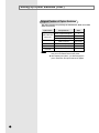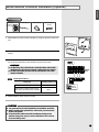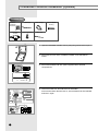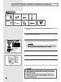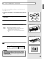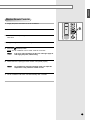
1
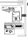
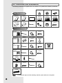
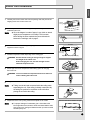
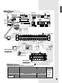
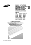
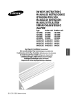
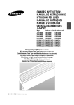
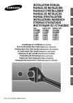
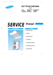
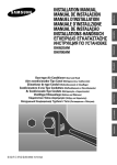
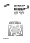
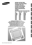
IDH1800E IDH2400E IDH3200E DH18ZA1(A2) DH24ZA1(A2) DH32ZA1(A2) UBH1800E UBH2400E UDH3200E DH18ZAX DH24ZAX DH32ZAX ENGLISH ESPAÑOL RUSSIAN E§§HNIKA Duct-type Air Conditioner (Cool and Heat) Aire acondicionador Tipo Canal (Refrigeración y Calefacción) Condizionatore d’aria Tipo Conduttura (Raffreddamento e Riscaldamento) Ar Condicionado Tipo Conduto (Refrigeração e Aquecimento) Climatiseur de type Conduit (Refroidissement et Chauffage) Ventiltype Klimaanlage (Kühlen und Wärmen) KÏÈÌ·ÙÈÛÙÈÎfi T‡Ô˘ AÂÚ·ÁˆÁÔ‡ (æ‡Í˘ Î·È £¤ÚÌ·ÓÛ˘) äÓ̉ˈËÓÌ ͇̇θÌÓ„Ó ÚËÔ‡ (éı·ʉÂÌËÂ Ë Ó·Ó„Â‚) ITALIANO ADH1800E ADH2400E ADH3200E DH18ZA1(A2) DH24ZA1(A2) DH32ZA1(A2) PORTUGUÊS Indoor unit Outdoor unit FRANÇAIS Type DEUTSCH INSTALLATION MANUAL MANUAL DE INSTALACION MANUALE PER L’INSTALLZIONE MANUAL DE INSTALAÇÕES MANUEL D’INSTALLATION GEBRAUCHSANWEISUNG E°XEIPI¢IO E°KATA™TA™H™ àçëíêìäñàü èé ìëíÄçéÇäÖ E S I P F D G R DB98-04155A(1) E-2 ENGLISH Contents ◆ PREPARING THE INSTALLATION ■ Deciding on Where to Install the Air Conditioner . . . . . . . . . . . . .4 ■ Air Conditioner and Accessories . . . . . . . . . . . . . . . . . . . . . . . . .6 ◆ INSTALLING THE INDOOR UNIT ■ Indoor Unit Installation . . . . . . . . . . . . . . . . . . . . . . . . . . . . . . . . .7 ■ Purging the Unit . . . . . . . . . . . . . . . . . . . . . . . . . . . . . . . . . . . . .8 ■ Connecting the connection cord . . . . . . . . . . . . . . . . . . . . . . . . .8 ■ Drain Hose Installation . . . . . . . . . . . . . . . . . . . . . . . . . . . . . . .10 ■ Drain Pump Installation (Optional) . . . . . . . . . . . . . . . . . . . . . . .11 ■ Connecting the Indoor Unit Assembly Piping . . . . . . . . . . . . . .12 ■ Cutting/Flaring the Pipes . . . . . . . . . . . . . . . . . . . . . . . . . . . . . .13 ◆ INSTALLING THE OUTDOOR UNIT ■ Connecting the Cables to the Outdoor Unit . . . . . . . . . . . . . . .14 ■ Checking Correct Grounding . . . . . . . . . . . . . . . . . . . . . . . . . . .15 ■ Connecting the Drain Hose to the Outdoor Unit . . . . . . . . . . . .16 ■ Fixing the Unit in Position . . . . . . . . . . . . . . . . . . . . . . . . . . . . .16 ◆ COMPLETING THE INSTALLATION ■ Connecting Up and Removing Air in the Circuit . . . . . . . . . . . .17 ■ Performing Leak Tests . . . . . . . . . . . . . . . . . . . . . . . . . . . . . . . .18 ■ Insulation . . . . . . . . . . . . . . . . . . . . . . . . . . . . . . . . . . . . . . . . . .19 ■ Increasing Fan Speed . . . . . . . . . . . . . . . . . . . . . . . . . . . . . . . .20 ◆ INSTALLING THE OPTIONAL ACCESSORIES ■ Setting Up Option switches . . . . . . . . . . . . . . . . . . . . . . . . . . . .21 ■ Wired Remote Controller Installation (Optional) . . . . . . . . . . . .25 ■ Centralized controller Installation (Optional) . . . . . . . . . . . . . . .26 ■ Wireless Remote Controller Installation (Optional) . . . . . . . . . .28 ■ Air Filter Installation (Optional) . . . . . . . . . . . . . . . . . . . . . . . . .29 ■ Controlling a Group . . . . . . . . . . . . . . . . . . . . . . . . . . . . . . . . . .30 ◆ OTHERS ■ Checking and Testing Operations . . . . . . . . . . . . . . . . . . . . . . .32 ■ Troubleshooting . . . . . . . . . . . . . . . . . . . . . . . . . . . . . . . . . . . . .34 ■ Explaining Operations to the Owner . . . . . . . . . . . . . . . . . . . . .36 ◆ TECHNICAL SPECIFICATIONS E-3 Deciding on Where to Install the Air Conditioner When deciding on the location of the air conditioner with the owner, the following restrictions must be taken into account. General Do NOT install the air conditioner in a location where it will come into contact with the following elements: ◆ Combustible gases ◆ Saline air ◆ Machine oil ◆ Sulphide gas ◆ Special environmental conditions If you must install the unit in such conditions, first consult your dealer. Indoor Unit ◆ There must be no obstacles near the air inlet and outlet. ◆ Choose a space of ceiling that enables the pipes and cables to be easily connected to the outdoor unit and the recommended length of 20 metres to be respected (“L” metres maximum-“L” indicated in the diagram on the page opposite). Proper drain hose passage should also be considered. ◆ Install the indoor unit on a ceiling that can support its weight. ◆ Maintain sufficient clearance around the indoor unit, as indicated in the diagram on the page opposite. ◆ Make sure that the water dripping from the drain hose runs away correctly and safely. Outdoor Unit ◆ The outdoor unit must NEVER be placed on its side or upside down, as the compressor lubrication oil will run into the cooling circuit and seriously damage the unit. ◆ Choose a location that is dry and sunny, but not exposed to direct sunlight or strong winds. ◆ Do not block any passageways or thoroughfares. ◆ Choose a location where the noise of the air conditioner when running and the discharged air do not disturb any neighbours. ◆ Choose a position that enables the pipes and cables to be easily connected to the indoor unit. Recommended length between indoor and outdoor unit is 20 metres.(“L” metres maximum) ◆ Install the outdoor unit on a flat, stable surface that can support its weight and does not generate any unnecessary noise and vibration. ◆ Position the outdoor unit so that the air flow is directed towards the open area. ◆ Maintain sufficient clearance around the outdoor unit, as indicated in the diagram on the page opposite. ◆ If the outdoor unit is installed at a height, ensure that its base is firmly fixed in position; the maximum height difference between indoor and outdoor unit is “H” metres(“H” indicated in the diagram on the page opposite.). ◆ Make sure that the water dripping from the drain hose runs away correctly and safely. CAUTION ◆ You have just purchased a duct-type air conditioner and it has been installed by your installation specialist. ◆ This device must be installed according to the national electrical rules. E-4 ENGLISH Respect the clearances and maximum lengths indicated in the diagram below when installing the unit. Liquid Refrigerant tube Gas Refrigerant tube ;;;;;;;; ;;;;;;;; ;;;;;;;; ;;;;;;;; “H”metres maximum Model L H ❊❊18❊❊ ❊❊24❊❊ ❊❊32❊❊ 30 30 30 15 15 15 Drain hose cm 10 10cm 35cm cm 15 ;;;;; ;;;; ;;;;; ;;;; ;;;;; Inspection access 450X450 400mm 270mm min. 1256mm 5mm min. Electrical component box 250mm 260mm Space requirement when installing the indoor unit 165mm 650mm air outlet duct flange Refrigerant connection port You must have 5mm or more space between the ceiling and the bottom of indoor unit. Otherwise, the noice from the vibration of indoor unit may bother the user. Space requirement when installing the air filter Rear of the indoor unit 165mm 165mm N o t e ◆ The air filter can be installed to the bottom or rear of the indoor unit. E-5 Air Conditioner and Accessories The following accessories are supplied with the air conditioner. The quantities are indicated in parantheses. Flare Nuts 3/8 (1) Basic Accessories Owner’s Instructions(1) NS NES OWNER'S INSTRUCTIO INSTRUCCIO MANUAL DE PER L'USO ISTRUZIONIINSTRUÇÕES MANUAL DE N MANUEL D'UTILISATIO ANWEISUNG GEBRAUCHS Air ConditionerSplit Splut-type Room doméstico sistema ad unità Separate Aire acondicionado d'aria per ambienti Condizionatorede ar condicionado tipo Split Aparelho type séparé Climatiseur de Geteilte raumklimaanlage Installation Manual(1) Insulation Drain B(1) Cable-Tie(4) Drain Plug(1) Air ConditionerSplit Splut-type Room doméstico sistema ad unità Separate Aire acondicionado d'aria per ambienti Condizionatorede ar condicionado tipo Split Aparelho type séparé Climatiseur de Geteilte raumklimaanlage Insulation outlet(1) Insulation inlet(1) Insulation Drain Pipe(1) ;; Pattern Sheet(1) NS NES OWNER'S INSTRUCTIO INSTRUCCIO MANUAL DE PER L'USO ISTRUZIONIINSTRUÇÕES MANUAL DE N MANUEL D'UTILISATIO ANWEISUNG GEBRAUCHS Flare Nuts 5/8 (1) Rubber Leg (4) ;;;; ;;;; ;;;; ;;;; ;;;; ;;;; Insulation Drain A(1) Insulation Cover Pipe(2) Nut(12) M4 X 12 Tapped Screw(4) Optional Accessories Wired Remote Controller(1) KR-H50110 Wireless Remote Controller(1) KR-H40100 Receiver & Display Unit(1) KRE-H2000 Cable-Tie(2) Cable Clamp(5) M4 X 16 Tapped Screw(7) Battery(2) M4 X 16 Tapped Screw(2) Remote Controller Holder(1) Cable-Tie(2) Cable Clamp(5) M4 X 16 Tapped Screw(7) Wire Kit KWE-A110 Length : 10m Centralized Controller(1) KR-H60110 Cable-Tie(2) Cable Clamp(5) Transmitter(1) KT-A00 Spacer Support(4) Cable-Tie(2) Drain Pump and Float Switch(1) KDP-075S0 M4 X 12 Tapped Screw(4) Cable-Tie(2) M4 X 16 Tapped Screw(7) Cable Clamp(2) Air Filter(1) KF-D0B0 Note E-6 ◆ Refrigeration pipes and their insulating materials, power cables are not supplied. ENGLISH Indoor Unit Installation 1 Carefully remove the indoor unit from the packing case and pull out the shipping block on the motor of the unit. Shipping block Place the pattern sheet on the ceiling at the spot where you want to install the indoor unit. Note ◆ Since the diagram is made of paper, it may shrink or stretch 2 slightly due to temperature or humidity. For this reason, before drilling the holes maintain the correct dimensions between the markings; refer to page 5. Concrete 3 Insert bolt anchors. Use existing ceiling supports or construct a suitable support as shown in figure. Insert Hole in anchor Hole in plug 4 Install the suspension bolts depending on the ceiling type. Suspension bolt(M8)-field supply IMPORTANT Ensure that the ceiling is strong enough to support the weight of the indoor unit. Before hanging the unit, test the strength of each attached suspension bolt. 5 Ceiling support Screw eight nuts to the suspension bolts making space for hanging the indoor unit. IMPORTANT You must install the suspension bolts more than four when installing the indoor unit. 6 Hang the indoor unit to the suspension bolts between two nuts. Note ◆ Tubing must be laid and connected inside the ceiling when suspending the unit. If the ceiling is already constructed, lay the tubing into position for connection to the unit before placing the unit inside the ceiling. 7 Screw the nuts to suspend the unit. 8 Adjust level of the unit by using measurement plate for all 4 sides. Note When the drain hose is installed to the right. ◆ For proper drainage of condensate, give a 3mm slant to the left or right side of the unit which will be connected with the drain hose, as shown in the figure. Make a tilt when you wish to install the drain pump, too. 3mm Drain tube outlet E-7 Purging the Unit On delivery, the indoor unit is loaded with an inert nitrogen gas. All this gas must therefore be purged before connecting the assembly piping. To purge the inert gas, proceed as follows. Unscrew the caps at the end of each pipe. Result: All inert gas escapes from the indoor unit. Note ◆ To prevent dirt or foreign objects from getting into the pipes during installation, do NOT remove the caps completely until you are ready to connect the piping. Connecting the Connection Cord The indoor unit is powered from the outdoor unit via the connection cord. 1 Remove the screw on the electrical component box and remove the cover plate. 2 Route the connection cord through the side of the indoor unit and connect the cable to terminals as shown in page 9. Note ◆ When connecting the cables, you must pass them through the cable clamp to fix them securely. Cable Clamp E-8 3 Route the other end of the cable to the outdoor unit through the ceiling & the hole on the wall. 4 Reassemble the electrical component box cover, carefully tightening the screw. 5 For further details on how to plug the other end of the connection cord into the outdoor unit, refer to page 14. ENGLISH Wiring Diagram CN20 Connector MAIN PCB SUB PCB DIP Switch SW2 CN7 Rotary Digital Switch SW1 Jumper Wire CN9 Receiver & Display Unit (Optional) Indoor Unit Transmitter (Optional) Ventilator Motor Power Float Switch Wired Remote Controller (Optional) Centralized Controller (Optional) Drain Pump MAIN POWER 220-240V~, 50Hz EARTH Communication Float Switch Drain Pump (Optional) Outdoor Unit MAIN POWER 220-240V~, 50Hz Cable Specifications The following electrical characteristics must be respected. MODEL ADH1800E/ADH2400E, DH18ZA1(A2)/DH24ZA1(A2) ADH3200E, DH32ZA1(A2) Power 1Ø, 220V-240V~, 50Hz Sub switch 30A Fuse 30A Min. size of electric Wires 2 H07RN-F, 4G, 1.0mm2 H07RN-F, 4G, 1.0mm from/to the indoor/outdoor unit 20m or less H07RN-F, 3G, 2.5mm2 H07RN-F, 3G, 4.0mm2 Size of electric 50m or less input wires H07RN-F, 3G, 4.0mm2 H07RN-F, 3G, 6.0mm2 Note The power cables are not supplied with the air conditioner. The user should purchase them separately. E-9 Drain Hose Installation Care must be taken when installing the drain hose for the indoor unit to ensure that any condensate water is correctly drained outside. The drain hose can be installed to the right or left side of the base pan. 1 Remove the rubber cap located on the side of the base pan depending on the situation. 2 Install the drain hose so that its length can be as short as possible. Internal diameter of the drain hose should be the same or slightly bigger than the external diameter. Cable-Tie Insulation drain pipe Drain hose Cable-Tie Insulation drain B Note Insulation drain A CAUTION Must fit tightly against body without any gap. 3 ◆ Give a 3mm slant to the drain hose for proper drainage of condensate ; refer to page 7. ◆ Secure the drain hose with the cable-tie not to be separated from the unit. Wrap the drain hose with the insulation drain pipe, the insulation drain A as shown in figure and secure them. And wrap the other drain tube outlet with the insulation drain B provided. CAUTION When not installing the drain pump When installing the drain pump Do not give the hose and upward gradient after the connection port. This will cause water to flow backwards when the unit is stopped, resulting in water leaks. If it is necessary to increase the height of the drain hose somewhat, the portion directly after 75cm. If it is raised higher than 75cm, there can be water leaks. ;;; ;;; Upward gradient 75cm or less Ceiling ;; Do not apply force to the piping on the unit side when connecting the drain hose. The hose should not be allowed to hang loose from its connection to the unit. Fasten the hose to a wall, frame or other support as close to the unit as possible. Support pieces Ceiling E-10 Ceiling ENGLISH Testing the drainage Prepare a little water about 5 liter. 1 Pour water into the base pan in the indoor unit as shown in figure. 2 Confirm that the water flows out through the drain hose. Drain Pump Installation (Optional) 1 Connect the cable to the electrical component box as shown in figure. Float switch 2 Drain pump Screw the drain pump to the side of the indoor unit with two screws. ◆ When installing the drain pump, leave a 7mm space between the bottom of the drain pan and the drain pump. Note Drain pump 7mm Bottom of the drain pan 3 Adjust the DIP switch(SW2) on the main PCB according to the table below. Switch No. Switch Position 2 3 ON ON Note Check below if the drain pump has been installed. Wrap the drain tube outlet on the right and left side of the indoor unit with an insulating materials. E-11 Connecting the Indoor Unit Assembly Piping Liquid refrigerant port There are two refrigerant pipes of differing diameters: ◆ A smaller one(9.52mm, 3/8") for the liquid refrigerant ◆ A larger one(15.88mm, 5/8") for the gas refrigerant A ◆ The thickness of tube should not less than 1.0mm. Gas refrigerant port Drain tube outlet ◆ The inside of copper tube must be clean & has no dust. The connection procedure for the refrigerant pipes varies according to the exit position of the pipes from the indoor unit, as seen when facing the indoor in the “A” side. ◆ Liquid refrigerant port ◆ Gas refrigerant port ◆ Drain hose tube outlet 1 Remove the protection caps on the pipes and connect the assembly pipes to each pipe, tightening the nuts, first manually and then with a wrench, a spaner applying the following torque. Outer Diameter 9.52 mm (3/8") 15.88 mm (5/8") Note a. When the indoor unit is above the outdoor unit Indoor unit Torque (kgf•cm) 300 750 ◆ If the pipes must be shortened refer to page 13. 2 Must use insulator which is thick enough to cover the refrigerant tube to protect the condensate water on the outside of pipe falling onto the floor and the efficiency of the unit will be better. 3 Cut off any excess foam insulation. 4 Be sure that there must be no crack or wave on the bended area. 5 It would be necessary to double the insulation thickness (10mm or more)to prevent condensation even on the insulator when if the installed area is warm and humid. 6 Shape an oil trap as shown in figure the oil trap must be formed every level difference of 6m. 7 For further details on connecting up to the outdoor unit and purging the refrigerant circuit, refer to page 17. Outdoor unit b. When the outdoor unit is above the indoor unit Outdoor unit Indoor unit Radius 5cm Oil trap (suction tube) E-12 Note ◆ The pipes will be insulated and fixed permanantly into position once the whole installation has been tested for gas leaks; refer to page 18 for further details. ENGLISH Cutting/Flaring the Pipes Connect the pipe within 50m and cutting pieces will not be gone into the pipe as being clean to pipe section. 1 Make sure that you have the required tools available (pipe cutter, reamer, flaring tool and pipe holder). 2 If you wish to shorten the pipes, cut it with a pipe cutter, taking care to ensure that the cut edge remains at a 90° angle with the side of the pipe. Refer to the illustrations below for examples of edges cut correctly and incorrectly. O 90 Oblique Rough Burr 3 To prevent any gas from leaking out, remove all burrs at the cut edge of the pipe, using a reamer. 4 Slide a flare nut on to the pipe and modify the flare. Outer Diameter(D) 9.52 mm (3/8") 15.88 mm (5/8") 5 Depth (A) 1.8 mm 2.2 mm Check that the flaring is correct, referring to the illustrations below for examples of incorrect flaring. Inclined Damaged Surface Cracked Uneven Thickness 6 Align the pipes and tighten the flare nuts first manually and then with a wrench, applying the following torque. Outer Diameter(D) Torque(kgf•cm) 9.52 mm (3/8") 300 15.88 mm (5/8") 750 7 For further details on how to connect up to the outdoor unit and purge the circuit, refer to page 17. CAUTION ◆ In case of welding the pipe, you must weld with nitrogen gas blowing. E-13 Connecting the Cables to the Outdoor Unit Two electric cables must be connected to the outdoor unit. ◆The connection cord connecting the indoor unit to the outdoor unit ◆The power cable connecting the auxiliary circuit breaker to the outdoor unit 1 Remove the terminal board cover on the side of the outdoor unit. 2 Connect the connection cord(N1, L1, C, terminals as shown in the diagram. 3 Connect the power cable to the auxiliary circuit breaker. An all pole disconnection from the power supply must be incorporated in the fixed wiring(≥3mm). 4 Replace the terminal board cover, carefully tightening the screw. ) and power cable(N, L) to Indoor Unit EARTH Power Outdoor Unit Power Cable Auxiliary circuit breaker Wiring Diagram CAUTION ◆ Keep the power cable and the connection cord in a steel pipe to protect them against liquids, outside impacts and so on. E-14 Communication ENGLISH Checking Correct Grounding If the power distribution circuit does not have an earth or the ground does not comply with specifications, an grounding electrode must be installed. 1 2 Select an grounding electrode that complies with the specifications given in the illustration. Determine a suitable location for the grounding electrode: ◆ In damp hard soil rather than loose sandy or gravel soil that has a higher grounding resistance ◆ Away from underground structures or facilities, such as gas pipes, water pipes, telephone lines and underground cables ◆ At least two metres away from a lightening conductor grounding electrode and its cable Note Steel core PVC-insulated green/ yellow wire, 2mm2 x 3.5 m Terminal M4 To grounding screw 50cm ◆ The grounding wire for the telephone line cannot be used to ground the air conditioner. 3 Finish wrapping insulating tape around the rest of the pipes leading to the outdoor unit. 4 Install a green/yellow coloured grounding wire (Ø1.6 mm, section 2 mm2 or greater): ◆ If the grounding wire is too short, connect an extension lead, in a mechanical way and wrapping it with insulating tape (do not bury the connection) ◆ Secure the grounding wire in position with staples Note Carbon plastic 30cm The corresponding accessories are NOT supplied with the air conditioner. ◆ If the grounding electrode is installed in an area of heavy traffic, its wire must be connected securely. 5 Carefully check the installation, by measuring the grounding resistance with a ground resistance tester. If the resistance is above required level, drive the electrode deeper into the ground or increase the number of grounding electrodes. 6 Connect the grounding wire to the electrical component box inside of the outdoor unit. E-15 Connecting the Drain Hose to the Outdoor Unit When using the air conditioner in the heating mode, ice may accumulate. During de-icing, the condensed water must be drained off safely. Consequently, you must install a drain hose on the outdoor unit, following the instructions below. 1 Make space more than 50mm between the bottom of the outdoor unit and the ground for installation of the drain hose, as shown in figure. 2 Insert the drain plug into the hole on the underside of the outdoor unit. 3 Connect the drain hose to the drain plug. 4 Ensure that the drained water runs off correctly and safely. 50mm min. 30mm Fixing the Unit in Position The outdoor unit must be installed on a rigid and stable base to avoid any increase in the noise level and vibration, particularly if the outdoor unit is to be installed close to a neighbour. If it is to be installed in a location exposed to strong winds or at a height, the unit must be fixed to an appropriate support (wall or ground). A 1 Position the outdoor unit so that the air flow is directed towards the outside. 2 Attach the outdoor unit to the appropriate support using anchor bolts. B 3 E-16 Capacity A B UBH1800E, DH18ZAX 582mm 340mm UBH2400E/UDH3200E, DH24ZAX/DH32ZAX 660mm 340mm If the outdoor unit is exposed to strong winds, install shield plates around the outdoor unit, so that the fan can operate correctly. ENGLISH Connecting Up and Removing Air In the Circuit The outdoor unit is loaded with sufficient R-22 refrigerant for 5 metres of piping. The air in the indoor unit and in the pipe must be purged. If air remains in the refrigeration pipes, it will affect the compressor, reduce to cooling/heating capacity and could lead to a malfunction. Refrigerant for air purging is not charged in the outdoor unit. Use Vacuum Pump as shown at the figure. <None>Adding Refrigerant Refrigerant must be added if the piping measures more than 5 metres in length (maximum of “A” metres). This operation can only be performed by a qualified refrigeration specialist. ☛ If you have used... Then... More than 5 metres of the pipes “B”g of refrigerant (R-22) must be added for each extra metre. Less than 5 metres of piping The purge time is normal B A Model a b ❊❊❊18❊❊❊ 40 50 30 ❊❊❊24❊❊❊ 40 50 30 ❊❊❊32❊❊❊ 55 55 30 For details about the installation situation(a or b), refer to page 12. Outdoor unit 1 Connect each assembly pipe to the appropriate valve on the outdoor unit and tighten the flare nut. 2 Referring to the illustration opposite, tighten the flare nut on section B first manually and then with a wrench, applying the following torque. Outer Diameter 9.52 mm (3/8") 15.88 mm (5/8 ") Gas pipe side C B Liquid pipe side D Torque (kgf•cm) 300 750 3 Connect the charging hose of low pressure side of manifold gauge to the packed valve having a service port as shown at the figure. 4 Open the valve of the low pressure side of manifold gauge counterclockwise. 5 Purge the air from the system using vacuum pump for about 10 minutes. ◆ Close the valve of the low pressure side of manifold gauge clockwise. ◆ Make sure that pressure gauge show -0.1MPa(-76cmHg) after about 10 minutes. This procedure is very important in order to avoid gas leak. ◆ Turn off the vacuum pump. ◆ Remove the hose of the low pressure side of manifold gauge. 6 Indoor unit A Set valve cork of both liquid side and gas side of packed valve to the open position. 7 Mount the valve stem nuts and the service port cap to the valve, and tighten them at the torque of 18N•m with a torque wrench. 8 Check for gas leakage. ◆ At this time, especially check for gas leakage from the 3-way valve’s stem nuts(A port), and from the service port cap. Vacuum pump A(gas) B(liquid) Valve stem E-17 Performing Leak Tests Before completing the installation (insulation of the hose and piping), you must check that there are no gas leaks. A B D C E-18 To check for gas leaks on the... Then, using a leak detector, check the... Indoor unit Flare nuts at the end of sections A and B. Outdoor unit Valves on sections C and D. Once you have checked that there are no leaks in the system, you can insulate the piping and hose. 1 To avoid condensation problems, place heat-resistant polyethylene foam separately around each refrigerant pipe. Note 2 ◆ Always make the seam of pipes face upwards. Wind insulating tape around the pipes. ; ; No gap Finish wrapping insulating tape around the rest of the pipes leading to the outdoor unit. ;; Heat resistant polyethylene foam(Insulation cover pipe) Body 3 ENGLISH Insulation Insulation cover pipe Insulation inlet/outlet Be sure to overlap the insulation CAUTION Must fit tightly against body without any gap. E-19 Increasing Fan Speed If external static pressure is too great(due to long extension of ducts, for example), the air flow volume may drop too low at each air outlet. This problem can be solved by increasing the fan speed using the following procedure. 1 Remove the screw on the electrical component box and remove the cover plate. 2 Adjust the DIP switch(SW2) on the main PCB to the “OFF” position. Switch No. Switch Position Function 5 ON OFF Normal speed High speed Re-install the cover plate and join the removed screw. 3 How to Read Diagram 1 The vertical axis is the external static pressure(mmAq) while the horizontal axis represents the AIR FLOW(m3/min). 2 The characteristic curves for ‘HH’, ‘H’, ‘Med’, and ‘Low’ fan speed controller are shown. 3 The nameplate values are shown based on the ‘H’ air flow. 4 In case of model IDH2400E and DH24ZA1(A2), the air flow is 17.4(m3/min), while the external static pressure is 4mmAq at ‘H’ position. 5 If external static pressure is too great, the air flow volume may drop too low as explained above. Note Air Flow (m3/min) E-20 IDH2400E, DH24ZA1(A2) IDH3200E, DH32ZA1(A2) mmAq mmAq mmAq IDH1800E, DH18ZA1(A2) HH : DIP Switch OFF position(High speed) H : At shipment(Normal speed) Air Flow (m3/min) Air Flow (m3/min) Setting Up Option Switches ENGLISH IMPORTANT : Before setting up the option switches, always make sure that you have turned off the main power. Main PCB in the Indoor Unit Rotary Digital Switch(SW1) A user can operate up to sixteen air conditioners by using the wired remote controller. Before controlling more than one air conditioner, you should connect the air conditioner each other. And you must assign addresses to the air conditioners. For further details on connecting air conditioners, refer to page 30. If the user would like to controller only one air conditioner, make sure that the arrow is at “0” position. Turn the arrow to the desired position referring to the table below. Switch No. Number of indoor unit(s) Switch No. Number of indoor unit(s) 0 One 8 Nine 1 Two 9 Ten 2 Three A Eleven 3 Four B Twelve 4 Five C Thirteen 5 Six D Fourteen 6 Seven E Fifteen 7 Eight F Sixteen DIP Switch(SW2) Adjust the switch to the desired position referring to the table below. Switch No. Option Item Switch Position ON OFF Note 1 Ventilator Fan Not installed Installed Not supplied 2 Drain Pump Installed Not installed 3 Float Switch Installed Not installed Optionally supplied 4 Filter Cleaning Cycle 1,000 hours 2,000 hours 5 Indoor Fan Motor Speed Normal High speed CAUTION If you do not adjust the switch when not installing the drain pump, "✼9" error will occurs. If this happens, adjust the No.2 and No.3 switches to the "OFF" position. E-21 Setting Up Option Switches (Cont.) Jumper Wire(SW05) You can adjust the setting temperature for heating. Cut off the SW05, depending on the situation. Option Item Situation of the Switch Note Setting temperature +2°C Short Preset Position Setting temperature +5°C Open Sub PCB in the Indoor Unit CN20 Connector Unit A (Address 0) CN20 Connector Remove the CN20 connector in the Sub PCB, if necessary, referring to the table below. (This procedure is needed only when the user would like to control a group by using the wired remote controller.) Address Situation of the CN20 Connector 0 Connected 1-F Removed Unit B (Address 1) Unit C (Address 2) Note ◆ Up to 16 air conditioners can be controlled with one wired remote controller. ◆ If the user does not want to control a group, do not remove the CN20 Connector. PCB in the Wired Remote Controller Dip Switch(DS01) Adjust the DIP switch No.2 and/or No.4 to the desired position referring to the table below. You must not adjust the switch 1 and 3. They should be in “OFF ” position at all times. E-22 Switch No. Option Item 2 Number of air conditioner(s) controlled by the wired remote controller 4 Using wireless remote controller Switch Position ON OFF Group controlling One indoor unit controlling Can be used Cannot be used ENGLISH Centralized Controller DIP Switch(DS01) Adjust the DIP switch to the desired position referring to the table below. Switch No. 1 2 3 4 Meaning The air conditioner is operated by the controller OFF OFF OFF OFF adjusted last among the wired remote controller, wireless remote controller and centralized controller. Switch OFF OFF OFF ON Position A user can use wired/wireless remote controller when the centralized controller is switched on. And he/she cannot use the remote controller(s) when the centralized controller is switched off. The air conditioner(s) can be controlled by only the OFF OFF ON OFF centralized controller. The user cannot use the wired/wireless remote controller in this case. ◆ You cannot install the centralized controller when the wired remote controller for a group has already been installed. Note Transmitter Rotary Digital Switch(DS01) A user can turn on/off up to sixteen air conditioners by using the centralized controller. To use the controller, you must assign addresses to the air conditioners. For further details on connecting air conditioners, refer to page 31. If the user would like to controller only one air conditioner, make sure that the arrow is at “0” position. Turn the arrow to the desired position referring to the table below. Switch No. Number of indoor unit(s) Switch No. Number of indoor unit(s) 0 One 8 Nine 1 Two 9 Ten 2 Three A Eleven 3 Four B Twelve 4 Five C Thirteen 5 Six D Fourteen 6 Seven E Fifteen 7 Eight F Sixteen E-23 Setting Up Option Switches (Cont.) Original Position of Option Switches The option switches are preset by the manufacturer. Refer to the table below, if necessary. Option Place Main PCB in the indoor unit State Rotary Digital Switch(SW1) 0 DIP Switch(SW2) ON Jumper Wire(SW05) SHORT Sub PCB in the indoor unit CN20 Connector Connected Wired Remote Controller DIP Switch(DS01) OFF Centralized Controller DIP Switch(DS01) OFF Transmitter Rotary Digital Switch(DS01) 0 Note E-24 Component No. ◆ Before setting up the options, always make sure that you have switched off the main power. ◆ After adjusting the options, you should supply the power. Otherwise, the options will not be applied. ENGLISH Wired Remote Controller Installation (Optional) Accessories Wired Remote Controller(1) KR-H50110 Cable-Tie(2) Cable Clamp(5) M4 X 16 Tapped Screw(7) 1 Disassemble the wired remote controller by using two grooves on the top of it. 2 Secure the rear cover of the wired remote controller on the wall with two screws. 3 Connect the R1, R2 and R3 terminals in the wired remote controller to the R1, R2 and R3 terminals on the electrical component box each. CAUTION ◆ Do NOT keep the wired remote controller cables with a 220V cable because the remote controller cables have low voltage. ◆ Do NOT input 220V power to the R1, R2 and R3 in the wired remote controller. Note 4 Indoor Unit Cable Specifications Cable type Double-insulation, 3G Size of cables 0.3mm2~0.75mm2 Max. length of electric wires from the indoor unit to the wired remote controller 100m Wired Remote Controller Reassemble the wired remote controller. CAUTION ◆ The optional kits must be installed by an installation specialist. ◆ Before installing the optional kits, ensure that you have turned off the main power. ◆ All optional kits cables should be installed according to the national wiring rules and you must install them in the wall not to be touched by users. E-25 Centralized Controller Installation (Optional) Accessories Centralized Controller(1) KR-H60110 Transmitter(1) KT-A00 Cable-Tie(2) Cable Clamp(5) Spacer Support(4) Cable-Tie(2) M4 X 16 Tapped Screw(7) 1 Open the centralized controller cover by using two grooves on the top of it. 2 Secure the rear cover of the centralized controller on the wall with two screws. 3 Secure the transmitter with four spacer supports into the electrical component box. 4 Connect the cable from the PCB and to the transmitter. And connect another cable from the O1, O2 terminals and to the transmitter as shown in figure. Electrical component box Transmitter E-26 ENGLISH 5 Connect the O1 and O2 terminals of the centralized controller to the O1 and O2 terminals on the electrical component box as shown in figure. CAUTION ◆ Do NOT keep the centralized controller cables with a 220V cable because the centralized controller cables have low voltage. Note Cable Specifications Cable type Double-insulation, 2G(Shield Cable) Size of cables 0.75mm2~1.25mm2 Centralized Controller 220-240V~, 50Hz Max. length of electric wires from the indoor unit to the centralized controller 6 Connect the power cables. Note 7 1km Cable Specifications Cable type Double-insulation, 2G Size of cables 0.75mm2~1.25mm2 Reassemble the centralized controller. CAUTION ◆ The optional kits must be installed by an installation specialist. ◆ Before installing the optional kits, ensure that you have turned off the main power. ◆ All optional kits cables should be installed according to the national wiring rules and you must install them in the wall not to be touched by users. E-27 Wireless Remote Controller Installation (Optional) Accessories Wireless Remote Controller(1) KR-H40100 Receiver & Display Unit(1) KRE-H2000 Battery(2) M4 X 16 Tapped Screw(2) Remote Controller Holder(1) Cable-Tie(2) Cable Clamp(5) M4 X 16 Tapped Screw(7) Wire Kit KWE-A110 Length : 10m 1 Remove the receiver & display unit cover by using the tab on the bottom of it. 2 Open the receiver & display unit. 3 Connect the end of the connector wire to the receiver & display unit and connect the other end of the wire to the electrical component box as shown in figure. CAUTION ◆ Do NOT keep the receiver & display unit cables with a 220V cable because the remote controller cables have low voltage. Receiver & Display Unit 4 Close the receiver & display unit. 5 Secure the receiver & display unit on the wall with two screws. 6 Reassemble the receiver & display unit cover. CAUTION ◆ The optional kits must be installed by an installation specialist. ◆ Before installing the optional kits, ensure that you have turned off the main power. ◆ All optional kits cables should be installed according to the national wiring rules and you must install them in the wall not to be touched by users. E-28 ENGLISH Air Filter Installation (Optional) The air filter can be installed to the bottom or rear of the indoor unit depending the situation. 1 Remove two screws securing on the levers under the bottom of the indoor unit. 2 Reassemble the levers making the other side face the indoor unit as shown in figure. 3 Turn the levers not to prevent inserting the air filter. 4 Insert the air filter into the indoor unit depending on the situation. Note 5 When installing to the bottom of the unit... ◆ Before inserting the air filter, remove the cover on the bottom of the unit removing the screws. ◆ Reinstall the cover on the rear of the unit after turning it 180°. Turn the levers to the original position to fix the air filter securely. Note Installing to the rear Installing to the bottom Setting Up Filter Cleaning Cycle ◆ Adjust the DIP switch(SW2) in the main PCB to the desired position referring the table below. Switch No. Switch Position Filter Cleaning Cycle 4 ON OFF 1,000 hours 2,000 hours CAUTION ◆ The optional kits must be installed by an installation specialist. ◆ Before installing the optional kits, ensure that you have turned off the main power. ◆ The optional air filter has to be cleaned only by an authorized person or service agent. E-29 Controlling a Group ∗ You should adjust the option switches in the electrical component box or on the PCB of the wired remote controller. ∗ Before setting up the option switches, always make sure that you have turned off the main power. ∗ After adjusting the options, you should supply the power. Otherwise, the options will not be applied. With Wired Remote Controller A user can operate up to sixteen air conditioners by using the wired remote controller In this case, the air conditioner can be controlled by only one wired remote controller connected to the indoor unit and cannot be controlled by the others. Unit A 1 Connect the R1, R2 and R3 terminals in the wired remote controller to the R1, R2 and R3 terminals in any indoor unit “A” each. Unit B 2 Connect the R1 and R3 terminals in the indoor unit “A” to the R1 and R3 terminals in another indoor unit “B”. CAUTION Unit C CN20 Connector When connecting the cables, you must keep these : ◆ The R1 terminals must be connected to the R1s. ◆ The R3 terminals must be connected to the R3s. ◆ Do not connect the R2 terminals to anywhere. If you connect R2 terminals, the PCB will be damaged. 3 Connect the R1 and R3 terminals of “B” to any indoor unit “C” and connect the others as the same way. 4 Adjust the rotary digital switch in the main PCB to the desired position referring to the table below. Number of indoor unit(s) Switch No. Number of indoor unit(s) 0 One 8 Nine 1 Two 9 Ten 2 Three A Eleven 3 Four B Twelve 4 Five C Thirteen 5 Six D Fourteen 6 Seven E Fifteen 7 Eight F Sixteen 5 Remove the CN20 connectors on the sub PCBs except the unit connected with remote controller(Adress “0”). 6 Adjust the DIP switch No. 2 in the wired remote controller to “ON” position. Note E-30 Switch No. You cannot install the centralized controller when the wired remote controller for a group has already been installed. ENGLISH With Centralized Controller A user can turn on/off up to sixteen air conditioners by using the centralized controller. In this case, the user can turn on/off all air conditioners or a specific air conditioner connected with the Centralized controller. And each air conditioner can be controlled by its own remote controller(s) depending on the setting. 1 Connect the O1 and O2 terminals in the Centralized controller to the O1 and O2 terminals in the indoor unit “A”. 2 Connect the O1 and O2 terminals in the indoor unit “A” to the O1 and O2 terminals in another indoor unit “B”. 3 Connect the O1 and O2 terminals of “B” to any indoor unit “C” and connect the others as the same way. 4 Adjust the DIP switch(DS01) in the centralized controller to the desired position referring to the table below. Switch No. 1 2 3 4 Meaning Centralized Controller The air conditioner is operated by the controller OFF OFF OFF OFF adjusted last among the wired remote controller, wireless remote controller and centralized controller. Switch OFF OFF OFF ON Position A user can use wired/wireless remote controller when the centralized controller is switched on. And he/she cannot use the remote controller(s) when the centralized controller is switched off. Unit A Unit B Unit C The air conditioner(s) can be controlled by only the OFF OFF ON OFF centralized controller. The user cannot use the wired/wireless remote controller in this case. 5 Adjust the rotary digital switch on the transmitter to the desired position referring to the table on page 23. Note Centralized Controller You cannot install the centralized controller when the wired remote controller for a group has already been installed. E-31 Checking and Testing Operations To complete the installation, perform the following checks and tests to ensure that the air conditioner is operating correctly. Review all the following elements in the installation: ◆ Piping connection tightness to detect any gas leakages ◆ Connecting wiring ◆ Heat-resistant insulation of the piping ◆ Drainage ◆ Earthing wire connection ◆ Correct operations(follow the steps below). Wired Remote Controller 1 Supply the power and switch on the air conditioner. 2 Press Test button more than 3 seconds without selecting any mode. Result: The air conditioner runs in COOL mode for 3 minutes. Note 3 Check that user's option(s) and the outdoor unit operate properly. Note 4 Do not attempt to select the operating mode or to adjust the temperature. It may switch the outdoor unit off. The air conditioner will switch it off automatically after 3 minutes. Note E-32 If the error code is displayed, fix the error referring to page 34. And supply the power, restart testing. If the air conditioner does not work because of switching off the thermistor sensor caused by the room temperature, you can operate the air conditioner by using Test button. ENGLISH Wireless Remote Controller 1 Supply the power and switch on the air conditioner. 2 Remove the remote controller batteries. 3 Insert the batteries pressing the On Timer and Off Timer buttons at the same time. 4 Stop pressing the buttons after inserting the batteries. 5 Press the (ON/OFF) button. Result: The air conditioner runs in COOL mode for 3 minutes. Note 6 Check that user’s option(s) and the outdoor unit operate properly. Note 7 If the error code is displayed, fix the error referring to page 35. And supply the power, restart testing. Do not attempt to select the operating mode or to adjust the temperature. It may switch the outdoor unit off. The air conditioner will switch it off automatically after 3 minutes. E-33 Troubleshooting Wired Remote Controller If the error occurs, and the error code are displayed on the wired remote controller. The error code blinks for 5 seconds and it disappears. If you would like to see the error code after disappearing it, press the Test button. Meaning of Error Code The error code is composed of two-digit figures or letters. The first means an indoor unit address and the second means an error code. Error Code Checking area ∗1 Indoor unit thermistor sensor error ◆ Indoor unit thermistor sensor ◆ PCB of the indoor unit ∗5 Indoor unit pipe thermistor sensor error ◆ Indoor unit pipe thermistor sensor ◆ PCB of the indoor unit ∗6 Outdoor unit thermistor sensor error ◆ Outdoor unit thermistor sensor ◆ PCB of the outdoor unit ∗9 Float switch error ◆ Drain pump, Float switch ◆ Drain system ◆ DIP switch(SW2) of the indoor unit (When the drain pump has not been installed, the No.2 and No.4 switches must be at "OFF" postion.) ∗A A Indoor and Outdoor communication error ◆ Communication cables of indoor and outdoor units ◆ PCB of indoor and outdoor units ∗C Wired remote controller communication error ◆ Wired remote controller cables, Wired remote controller ◆ Main/Sub PCB of the indoor unit ∗D Outdoor pipe thermistor sensor error ◆ Outdoor pipe thermistor sensor ◆ PCB of the outdoor unit Example E-34 Meaning “39” means the address “3” indoor unit has a trouble with a float switch. ENGLISH Wireless Remote Controller If the error occurs, the indicators on the receiver & display unit displays the error. Meaning of Error Code Indicators Meaning Checking area Timer Operating Filter ▲ ▲ ▲ ▲ : OFF ▲ ▲ Indoor unit thermistor sensor error ◆ Indoor unit thermistor sensor ◆ PCB of the indoor unit Indoor unit pipe thermistor sensor error ◆ Indoor unit pipe thermistor sensor ◆ PCB of the indoor unit Outdoor unit thermistor sensor error ◆ Outdoor unit thermistor sensor ◆ PCB of the outdoor unit Float switch error ◆ Drain pump, Float switch ◆ Drain system Indoor and Outdoor communication error ◆ Communication cables of indoor and outdoor units ◆ PCB of indoor and outdoor units Wired remote controller communication error ◆ Wired remote controller cables, Wired remote controller ◆ Main/Sub PCB of the indoor unit Outdoor pipe thermistor sensor error ◆ Outdoor pipe thermistor sensor ◆ PCB of the outdoor unit : Blinking ▲ ▲ : Blinking at once : Blinking alternately E-35 Explaining Operations to the Owner Before leaving the premises on which you have installed the air conditioner, you should explain the following operations to the owner, making reference to the appropriate pages in the owner’s instruction booklet. 1 How to start and stop the air conditioner. 2 How to select the operating mode and adjust the temperature and fan settings. 3 How to set the timers. 4 How to remove and clean the air filter, if installed. Once the owner is happy with the basic operations, hand over the owner’s instruction booklet and this installation manual for storage in a handy and safe place. E-36 ENGLISH Technical Specifications Model Power Supply ADH1800E ADH2400E ADH3200E 1Ø, 220-240V~, 50Hz DH18ZA1(A2) DH24ZA1(A2) DH32ZA1(A2) E-37 THIS AIR CONDITIONER IS MANUFACTURED BY: ESTE AIRE ACONDICIONADO HA SIDO FABRICADO POR: QUESTO CONDIZIONATORE D’ARIA È PRODOTTO DA: ESTE APARELHO DE AR CONDICIONADO É FABRICADO POR: CE CLIMATISEUR EST FABRIQUE PAR: DIESE KLIMAANLAGE IST FABRIZIERT VON: AYTH H ™Y™KEYH KATA™KEYA™THKE A¶O : ùíéí äéçÑàñàéçÖê àáÉéíéÇãÖç îàêåéâ: ELECTRONICS Printed in Korea