1
SyncMaster 400UX,460UX
LCD Monitor
User Manual
Introduction
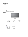
-- 400UX -Package Contents
Note
Please make sure the following items are included with your LCD Display.
If any items are missing, contact your dealer.
Contact a local dealer to buy optional items.
Note
This stand is not for the Floor Standing Type.
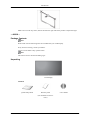
Unpacking
LCD Display
Manuals
Quick Setup Guide
Warranty Card
(Not available in all locations)
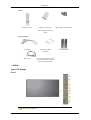
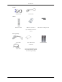
Cables
D-Sub Cable
Power Cord
User's Guide
Introduction
Others
Remote Control
Batteries (AAA X 2)
BNC to RCA Adaptor Jack
(Not available in all locations)
Sold separately
DVI Cable
Wall Mount KIT
Calibrater
BNC Cable
For more information on the
use of the calibrater, see Natural Color Expert Help.
-- 400UX -Your LCD Display
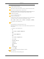
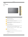
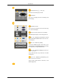
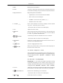
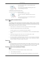
Front
MENU button [MENU]
Semi Stand KIT
Introduction
Opens the on-screen menu and exits from the menu. Also use to exit the OSD menu
or return to the previous menu.
Navigate buttons (Up-Down buttons)
Moves from one menu item to another vertically or adjusts selected menu values.
Adjust buttons (Left-Right buttons) / Volume buttons
Moves from one menu item to another horizontally or adjusts selected menu values. When OSD is not on the screen, push the button to adjust volume.
ENTER button [ENTER]
Activates a highlighted menu item.
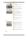
SOURCE button [SOURCE]
Switches from PC mode to Video mode. Changing the source is only allowed for
external devices that are connected to the LCD Display at the time.
[PC] → [BNC] → [DVI] → [AV] → [S-Video] → [Component] → [HDMI]
>> Click here to see an animation clip
PIP
Push the PIP button to turn the PIP screen On / Off.
More than one PIP cannot overlap on screen as BNC and the component use the
same terminal.
>> Click here to see an animation clip
•
PC
AV / S-Video / Component / HDMI Mode
•
BNC
AV / S-Video / HDMI Mode
•
DVI
AV / S-Video / Component Mode
•
AV / S-Video
PC / BNC / DVI Mode
•
Component
PC / DVI Mode
•
HDMI
PC / BNC Mode
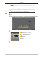
Power button [
]
Use this button for turning the LCD Display on and off.
Power indicator
Shows PowerSaver mode by blinking green
Introduction
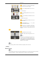
Note
See PowerSaver described in the manual for further information regarding power
saving functions. For energy conservation, turn your LCD Display OFF when it
is not needed or when leaving it unattended for long periods.
Remote Control Sensor
Aim the remote control towards this spot on the LCD Display.
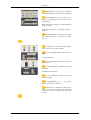
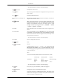
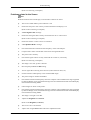
Rear
Note
For detailed information concerning cable connections, refer to Connecting Cables under Setup. The
LCD Display 's configuration at the back may vary slightly depending on the LCD Display model.
POWER S/W ON [ │ ] / OFF [O]
Switches the LCD Display On/Off.
POWER IN
The power cord plugs into the LCD Display and
the wall plug.
Introduction
REMOTE OUT/IN
You can use a wired remote control by connecting
it to your LCD Display.
RS232C OUT/IN (RS232C Serial PORT)
MDC(Multiple Display Control) Program Port
DVI / PC / HDMI IN [PC/DVI/BNC AUDIO
IN] (PC/DVI/BNC/HDMI Audio Connection Terminal (Input))
DVI / PC / HDMI IN [HDMI]
Connect the HDMI terminal at the back of your
LCD Display to the HDMI terminal of your digital output device using a HDMI cable.
DVI / PC / HDMI IN [RGB](PC Video Connection Terminal)
Using a D-Sub Cable (15 pin D-Sub) - PC mode
(Analog PC)
DVI / PC / HDMI IN [DVI(HDCP)] (PC
Video Connection Terminal)
Using a DVI Cable (DVI-D to DVI-D) - DVI
mode (Digital PC)
COMPONENT AUDIO IN [L-AUDIO-R]
(Component Audio Connection Terminal (Input))
BNC/COMPONENT OUT [R/PR, G/Y, B/
PB, H, V] (BNC/Component Connection Terminal (Output))
BNC (Analog PC) Connection: connecting the R,
G, B, H, V ports
Component Connection: connecting the PR, Y,
PB ports
BNC/COMPONENT IN [R/PR, G/Y, B/PB,
H, V](BNC/Component Connection Terminal
(Input))
Introduction
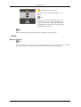
AV AUDIO IN [L-AUDIO-R] (LCD Display
Audio Connection Terminal (Input))
AV OUT [VIDEO](VIDEO Connection Terminal)
AV mode (Output)
AV IN [VIDEO](VIDEO Connection Terminal) (Input)
AV OUT [S-VIDEO] (S-VIDEO Connection
Terminal)
S-VIDEO mode (Output)
AV IN [S-VIDEO](S-VIDEO Connection
Terminal) (Input)
EXT SPEAKER(8 Ω)[- - L - +, - - R - +] (EXT
Speaker Connection Terminal)
AUDIO OUT [L-AUDIO-R] (LCD Display
Audio Connection Terminal (Output))AUDIO
OUT is the terminal for sound output of PC, DVI
or BNC.
USB(USB Connection Terminal)
Keyboard / Mouse, Mass Storage Device Compatible.
Note
The number of LCD Displays that can be connected to loopout may differ depending on the
cables, signal source etc. With cables where there
is no degradation or signal source, up to ten LCD
Displays can be connected.
Note
See Connecting Cables for further information regarding cable connections.
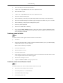
-- 400UX -Remote Control
Note
The performance of the remote control may be affected by a TV or other electronic device operating
near the LCD Display , causing a malfunction due to interference with the frequency.
Introduction
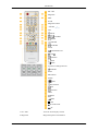
ON / OFF
MagicInfo
MDC
LOCK
MagicInfo buttons
+100 DEL
VOL
MUTE
TTX/MIX
MENU
ENTER
P.MODE
AUTO
ENTER/PRE-CH
CH/P
SOURCE
INFO
EXIT
Up-Down Left-Right buttons
S.MODE
STILL
FM RADIO
P.SIZE
SRS
DUAL/MTS
PIP
SOURCE
SWAP
SIZE
REW
STOP
PLAY/PAUSE
FF
1. ON / OFF
Turns the LCD Display On/Off.
2. MagicInfo
MagicInfo Quick Launch Button.
Introduction
3. MDC
MDC Quick Launch Button.
4. LOCK
Activates or deactivates all function keys on both the remote control and the LCD Display except for the Power and LOCK buttons.
5. MagicInfo buttons
MagicInfo Quick Launch Button.
6. +100 DEL
•
Alphanumeric: Used to enter the Internet address.
•
DEL: Functions as the backspace.
•
SYMBOL: Used to enter the symbols. (.O_-)
•
ENTER: Used to enter values.
Press to select channels over 100. For example, to select channel
121, press "+100", then press "2" and "1".
- This fuction does not work for this LCD Display.
7. VOL
8.
Adjusts the audio volume.
MUTE
9.
TTX/MIX
Pauses (mutes) the audio output temporarily. This is displayed on
the lower left corner of the screen. The audio resumes if MUTE
or - VOL + is pressed in the Mute mode.
TV channels provide text information services via teletext.
- This fuction does not work for this LCD Display.
10.
MENU
Opens the on-screen menu and exits from the menu screen or
closes the screen adjustment menu.
11.
ENTER
Activates a highlighted menu item.
12.
P.MODE
When you press this button, current picture mode is displayed on
the lower center of the screen.
AV / S-Video / Component : P.MODE
The LCD Display has four automatic picture settings that are preset at the factory. Then push button again to circle through available preconfigured modes. ( Dynamic → Standard → Movie
→ Custom )
PC / DVI / BNC : M/B (MagicBright)
MagicBright is a new feature providing the optimum viewing
environment depending on the contents of the image you are
watching. Then push button again to circle through available preconfigured modes. (Entertain → Internet → Text → Custom )
13. AUTO
14.
ENTER/PRE-CH
Adjusts the screen display automatically in PC mode. By changing
the resolution in the control panel, auto function is performed.
Returns to the immediately previous channel.
- This fuction does not work for this LCD Display.
15.
CH/P
In TV mode, selects TV channels.
Introduction
- This fuction does not work for this LCD Display.
16.
SOURCE
Changes the video source.
17.
INFO
The current picture information is displayed in the top left corner
of the screen.
18.
EXIT
Exits from the menu screen.
19. Up-Down Left-Right buttons
20.
S.MODE
Moves from one menu item to another horizontally, vertically or
adjusts selected menu values.
When pressing this button, the current mode is displayed at the
bottom centre of the screen. The LCD Display has a built-in high
fidelity stereo amplifier. Then press the button again to circle
through available preconfigured modes. ( Standard → Music
→ Movie → Speech → Custom )
21. STILL
Press the button once to freeze the screen. Press it again to unfreeze.
22. FM RADIO
Turns the FM Radio on/off. In PC/DVI mode, sets the SOUND
to FM Radio. In general Video mode, selects FM Radio, and turns
off the screen. In areas where the signal is weak, noise may occur
during FM radio broadcasts.
- This fuction does not work for this LCD Display.
23. P.SIZE
Press to change the screen size.
24.
SRS
25.
SRS
DUAL/MTS
DUALSTEREO/MONO, DUAL l / DUAL ll and MONO/NICAM
MONO/NICAM STEREO can be operated depending on the
broadcasting type by using the DUAL button on the remote control
while watching TV.
MTSYou can select MTS (Multichannel Television Stereo) mode.
FM Stereo
Audio Type
MTS/S_Mode
Default
Mono
Mono
Manual Change
Stereo
Mono ↔ Stereo
SAP
Mono ↔ SAP
Mono
- This fuction does not work for this LCD Display.
26.
PIP
Every time you press the button, a PIP screen appears.
27.
SOURCE
Changes the source of the PIP window signal.
28. SWAP
Swaps the contents of the PIP and main image. The image in the
PIP window will appear on the main screen, and the main screen
image will appear in the PIP window.
Introduction
29.
SIZE
Switches the PIP Picture Size.
30.
REW
Rewind
31.
32.
33.
STOP
PLAY / PAUSE
FF
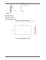
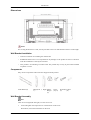
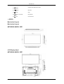
-- 400UX -Mechanical Layout
Mechanical Layout
NETWORK MODEL SIZE
Stop
Play/Pause
Fast forward
Introduction
LCD Display Head
NETWORK MODEL SIZE
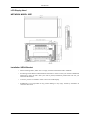
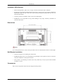
Installation VESA Bracket
•
When installing VESA, make sure to comply with the international VESA standards.
•
Purchasing VESA Bracket and Installation Information : Please contact your nearest SAMSUNG
Distributor to place an order. After your order is placed, installation professionals will visit you
and install the bracket.
•
At least 2 persons are needed in order to move the LCD Display.
•
SAMSUNG is not responsible for any product damage or any injury caused by installation at
customer's discretion.
Introduction
Dimensions
Notice
For securing the bracket on a wall, use only machine screws of 6 mm diameter and 8 to 12 mm length.
Wall Bracket Installation
•
Contact a technician for installing the wall bracket.
•
SAMSUNG Electronics is not responsible for any damages to the product or harm to customers
when the installation is done by the customer.
•
This product is for installing on cement walls. The product may not stay in place when installed
on plaster or wood.
Components
Only use the components and accessories shipped with the product.
Wall Bracket(1)
Hinge(Left 1, Right Plastic
1)
Hanger
(4)
Screw
(A)(11)
Screw(B) Anchor
(4)
(11)
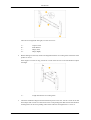
Wall Bracket Assembly
Note
There are two hinges(left and right). Use the correct one.
1.
Insert and tighten the Captive Screw in the direction of the arrow.
When done, mount the wall bracket on the wall.
Introduction
There are two hinges(left and right). Use the correct one.
2.
A-
Captive Screw
B-
Wall Bracket
C-
Hinge (Left)
D-
Hinge (Right)
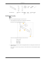
Before drilling into the wall, check if the length between the two locking holes at the back of the
product is correct.
If the length is too short or long, loosen all or some of the 4screws on the wall bracket to adjust
the length.
A-
3.
Length between the two locking holes
Check the installation diagram and mark the drill points on the wall. Use the 5.0 mm bit to drill
holes deeper than 35 mm. Fix each anchor in the corresponding hole. Match each of the brackets
and hinge holes to the corresponding anchor holes and insert and tighten the 11 screws A.
Introduction
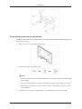
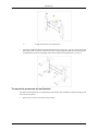
To mount the product on the wall bracket
The shape of the product may vary depending on the model. (The assemblies of the plastic hanger and
the screw are the same)
1.
Remove the 4 screws on the back of the product.
2.
Insert the screw B into the plastic hanger.
Notice
3.
•
Mount the product on the wall bracket and make sure it is properly fixed to the left and right
plastic hangers.
•
Be careful when installing the product on the bracket as fingers can be caught in the holes.
•
Make sure the wall bracket is securely fixed to the wall, or the product may not stay in place
after installation.
Tighten the 4 screws in step 2 (plastic hanger + screw B)to the rear holes of the product.
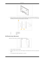
Introduction
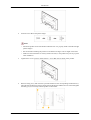
4.
Remove safety pin (3) and insert the 4 product holders into the corresponding bracket holes (1).
Then place the product(2) so that it is firmly fixed to the bracket. Make sure to re-insert and tighten
the safety pin (3) to securely hold the product to the bracket.
A-
LCD Display
B-
Wall Bracket
C-
Wall
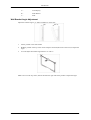
Wall Bracket Angle Adjustment
Adjust the bracket angle to -2° before installing it on the wall.
1.
Fix the product to the wall bracket.
2.
Hold the product at the top in the center and pull it forward (direction of the arrow) to adjust the
angle.
3.
You can adjust the bracket angle between -2° and 15°.
Introduction
Make sure to use the top center, and not the leftor the right side of the product to adjust the angle.
-- 460UX -Package Contents
Note
Please make sure the following items are included with your LCD Display.
If any items are missing, contact your dealer.
Contact a local dealer to buy optional items.
Note
This stand is not for the Floor Standing Type.
Unpacking
LCD Display
Manuals
Quick Setup Guide
Warranty Card
(Not available in all locations)
User's Guide
Introduction
Cables
D-Sub Cable
Power Cord
Remote Control
Batteries (AAA X 2)
Others
BNC to RCA Adaptor Jack
(Not available in all locations)
Sold separately
DVI Cable
Wall Mount KIT
Calibrater
BNC Cable
For more information on the
use of the calibrater, see Natural Color Expert Help.
Semi Stand KIT
Introduction
-- 460UX -Your LCD Display
Front
MENU button [MENU]
Opens the on-screen menu and exits from the menu. Also use to exit the OSD menu
or return to the previous menu.
Navigate buttons (Up-Down buttons)
Moves from one menu item to another vertically or adjusts selected menu values.
Adjust buttons (Left-Right buttons) / Volume buttons
Moves from one menu item to another horizontally or adjusts selected menu values. When OSD is not on the screen, push the button to adjust volume.
ENTER button [ENTER]
Activates a highlighted menu item.
SOURCE button [SOURCE]
Switches from PC mode to Video mode. Changing the source is only allowed for
external devices that are connected to the LCD Display at the time.
[PC] → [BNC] → [DVI] → [AV] → [S-Video] → [Component] → [HDMI]
>> Click here to see an animation clip
PIP
Push the PIP button to turn the PIP screen On / Off.
More than one PIP cannot overlap on screen as BNC and the component use the
same terminal.
>> Click here to see an animation clip
•
PC
Introduction
AV / S-Video / Component / HDMI Mode
•
BNC
AV / S-Video / HDMI Mode
•
DVI
AV / S-Video / Component Mode
•
AV / S-Video
PC / BNC / DVI Mode
•
Component
PC / DVI Mode
•
HDMI
PC / BNC Mode
Power button [
]
Use this button for turning the LCD Display on and off.
Power indicator
Shows PowerSaver mode by blinking green
Note
See PowerSaver described in the manual for further information regarding power
saving functions. For energy conservation, turn your LCD Display OFF when it
is not needed or when leaving it unattended for long periods.
Remote Control Sensor
Aim the remote control towards this spot on the LCD Display.
Rear
Note
For detailed information concerning cable connections, refer to Connecting Cables under Setup. The
LCD Display 's configuration at the back may vary slightly depending on the LCD Display model.
Introduction
POWER S/W ON [ │ ] / OFF [O]
Switches the LCD Display On/Off.
POWER IN
The power cord plugs into the LCD Display and
the wall plug.
REMOTE OUT/IN
You can use a wired remote control by connecting
it to your LCD Display.
RS232C OUT/IN (RS232C Serial PORT)
MDC(Multiple Display Control) Program Port
DVI / PC / HDMI IN [PC/DVI/BNC AUDIO
IN] (PC/DVI/BNC/HDMI Audio Connection Terminal (Input))
DVI / PC / HDMI IN [HDMI]
Connect the HDMI terminal at the back of your
LCD Display to the HDMI terminal of your digital output device using a HDMI cable.
DVI / PC / HDMI IN [RGB](PC Video Connection Terminal)
Using a D-Sub Cable (15 pin D-Sub) - PC mode
(Analog PC)
DVI / PC / HDMI IN [DVI(HDCP)] (PC
Video Connection Terminal)
Using a DVI Cable (DVI-D to DVI-D) - DVI
mode (Digital PC)
Introduction
COMPONENT AUDIO IN [L-AUDIO-R]
(Component Audio Connection Terminal (Input))
BNC/COMPONENT OUT [R/PR, G/Y, B/
PB, H, V] (BNC/Component Connection Terminal (Output))
BNC (Analog PC) Connection: connecting the R,
G, B, H, V ports
Component Connection: connecting the PR, Y,
PB ports
BNC/COMPONENT IN [R/PR, G/Y, B/PB,
H, V](BNC/Component Connection Terminal
(Input))
AV AUDIO IN [L-AUDIO-R] (LCD Display
Audio Connection Terminal (Input))
AV OUT [VIDEO](VIDEO Connection Terminal)
AV mode (Output)
AV IN [VIDEO](VIDEO Connection Terminal) (Input)
AV OUT [S-VIDEO] (S-VIDEO Connection
Terminal)
S-VIDEO mode (Output)
AV IN [S-VIDEO](S-VIDEO Connection
Terminal) (Input)
EXT SPEAKER(8 Ω)[- - L - +, - - R - +] (EXT
Speaker Connection Terminal)
AUDIO OUT [L-AUDIO-R] (LCD Display
Audio Connection Terminal (Output))AUDIO
OUT is the terminal for sound output of PC, DVI
or BNC.
Introduction
USB(USB Connection Terminal)
Keyboard / Mouse, Mass Storage Device Compatible.
Note
The number of LCD Displays that can be connected to loopout may differ depending on the
cables, signal source etc. With cables where there
is no degradation or signal source, up to ten LCD
Displays can be connected.
Note
See Connecting Cables for further information regarding cable connections.
-- 460UX -Remote Control
Note
The performance of the remote control may be affected by a TV or other electronic device operating
near the LCD Display , causing a malfunction due to interference with the frequency.
Introduction
ON / OFF
MagicInfo
MDC
LOCK
MagicInfo buttons
+100 DEL
VOL
MUTE
TTX/MIX
MENU
ENTER
P.MODE
AUTO
ENTER/PRE-CH
CH/P
SOURCE
INFO
EXIT
Up-Down Left-Right buttons
S.MODE
STILL
FM RADIO
P.SIZE
SRS
DUAL/MTS
PIP
SOURCE
SWAP
SIZE
REW
STOP
PLAY/PAUSE
FF
1. ON / OFF
Turns the LCD Display On/Off.
2. MagicInfo
MagicInfo Quick Launch Button.
Introduction
3. MDC
MDC Quick Launch Button.
4. LOCK
Activates or deactivates all function keys on both the remote control and the LCD Display except for the Power and LOCK buttons.
5. MagicInfo buttons
MagicInfo Quick Launch Button.
6. +100 DEL
•
Alphanumeric: Used to enter the Internet address.
•
DEL: Functions as the backspace.
•
SYMBOL: Used to enter the symbols. (.O_-)
•
ENTER: Used to enter values.
Press to select channels over 100. For example, to select channel
121, press "+100", then press "2" and "1".
- This fuction does not work for this LCD Display.
7. VOL
8.
Adjusts the audio volume.
MUTE
9.
TTX/MIX
Pauses (mutes) the audio output temporarily. This is displayed on
the lower left corner of the screen. The audio resumes if MUTE
or - VOL + is pressed in the Mute mode.
TV channels provide text information services via teletext.
- This fuction does not work for this LCD Display.
10.
MENU
Opens the on-screen menu and exits from the menu screen or
closes the screen adjustment menu.
11.
ENTER
Activates a highlighted menu item.
12.
P.MODE
When you press this button, current picture mode is displayed on
the lower center of the screen.
AV / S-Video / Component : P.MODE
The LCD Display has four automatic picture settings that are preset at the factory. Then push button again to circle through available preconfigured modes. ( Dynamic → Standard → Movie
→ Custom )
PC / DVI / BNC : M/B (MagicBright)
MagicBright is a new feature providing the optimum viewing
environment depending on the contents of the image you are
watching. Then push button again to circle through available preconfigured modes. (Entertain → Internet → Text → Custom )
13. AUTO
14.
ENTER/PRE-CH
Adjusts the screen display automatically in PC mode. By changing
the resolution in the control panel, auto function is performed.
Returns to the immediately previous channel.
- This fuction does not work for this LCD Display.
15.
CH/P
In TV mode, selects TV channels.
Introduction
- This fuction does not work for this LCD Display.
16.
SOURCE
Changes the video source.
17.
INFO
The current picture information is displayed in the top left corner
of the screen.
18.
EXIT
Exits from the menu screen.
19. Up-Down Left-Right buttons
20.
S.MODE
Moves from one menu item to another horizontally, vertically or
adjusts selected menu values.
When pressing this button, the current mode is displayed at the
bottom centre of the screen. The LCD Display has a built-in high
fidelity stereo amplifier. Then press the button again to circle
through available preconfigured modes. ( Standard → Music
→ Movie → Speech → Custom )
21. STILL
Press the button once to freeze the screen. Press it again to unfreeze.
22. FM RADIO
Turns the FM Radio on/off. In PC/DVI mode, sets the SOUND
to FM Radio. In general Video mode, selects FM Radio, and turns
off the screen. In areas where the signal is weak, noise may occur
during FM radio broadcasts.
- This fuction does not work for this LCD Display.
23. P.SIZE
Press to change the screen size.
24.
SRS
25.
SRS
DUAL/MTS
DUALSTEREO/MONO, DUAL l / DUAL ll and MONO/NICAM
MONO/NICAM STEREO can be operated depending on the
broadcasting type by using the DUAL button on the remote control
while watching TV.
MTSYou can select MTS (Multichannel Television Stereo) mode.
FM Stereo
Audio Type
MTS/S_Mode
Default
Mono
Mono
Manual Change
Stereo
Mono ↔ Stereo
SAP
Mono ↔ SAP
Mono
- This fuction does not work for this LCD Display.
26.
PIP
Every time you press the button, a PIP screen appears.
27.
SOURCE
Changes the source of the PIP window signal.
28. SWAP
Swaps the contents of the PIP and main image. The image in the
PIP window will appear on the main screen, and the main screen
image will appear in the PIP window.
Introduction
29.
SIZE
Switches the PIP Picture Size.
30.
REW
Rewind
31.
32.
33.
STOP
PLAY / PAUSE
FF
-- 460UX -Mechanical Layout
Mechanical Layout
NETWORK MODEL SIZE
LCD Display Head
NETWORK MODEL SIZE
Stop
Play/Pause
Fast forward
Introduction
Installation VESA Bracket
•
When installing VESA, make sure to comply with the international VESA standards.
•
Purchasing VESA Bracket and Installation Information : Please contact your nearest SAMSUNG
Distributor to place an order. After your order is placed, installation professionals will visit you
and install the bracket.
•
At least 2 persons are needed in order to move the LCD Display.
•
SAMSUNG is not responsible for any product damage or any injury caused by installation at
customer's discretion.
Dimensions
Notice
For securing the bracket on a wall, use only machine screws of 6 mm diameter and 8 to 12 mm length.
Wall Bracket Installation
•
Contact a technician for installing the wall bracket.
•
SAMSUNG Electronics is not responsible for any damages to the product or harm to customers
when the installation is done by the customer.
•
This product is for installing on cement walls. The product may not stay in place when installed
on plaster or wood.
Components
Only use the components and accessories shipped with the product.
Introduction
Wall Bracket(1)
Hinge(Left 1, Right Plastic
1)
Hanger
(4)
Screw
(A)(11)
Screw(B) Anchor
(4)
(11)
Wall Bracket Assembly
Note
There are two hinges(left and right). Use the correct one.
1.
Insert and tighten the Captive Screw in the direction of the arrow.
When done, mount the wall bracket on the wall.
There are two hinges(left and right). Use the correct one.
2.
A-
Captive Screw
B-
Wall Bracket
C-
Hinge (Left)
D-
Hinge (Right)
Before drilling into the wall, check if the length between the two locking holes at the back of the
product is correct.
If the length is too short or long, loosen all or some of the 4screws on the wall bracket to adjust
the length.
Introduction
A3.
Length between the two locking holes
Check the installation diagram and mark the drill points on the wall. Use the 5.0 mm bit to drill
holes deeper than 35 mm. Fix each anchor in the corresponding hole. Match each of the brackets
and hinge holes to the corresponding anchor holes and insert and tighten the 11 screws A.
To mount the product on the wall bracket
The shape of the product may vary depending on the model. (The assemblies of the plastic hanger and
the screw are the same)
1.
Remove the 4 screws on the back of the product.
Introduction
2.
Insert the screw B into the plastic hanger.
Notice
•
Mount the product on the wall bracket and make sure it is properly fixed to the left and right
plastic hangers.
•
Be careful when installing the product on the bracket as fingers can be caught in the holes.
•
Make sure the wall bracket is securely fixed to the wall, or the product may not stay in place
after installation.
3.
Tighten the 4 screws in step 2 (plastic hanger + screw B)to the rear holes of the product.
4.
Remove safety pin (3) and insert the 4 product holders into the corresponding bracket holes (1).
Then place the product(2) so that it is firmly fixed to the bracket. Make sure to re-insert and tighten
the safety pin (3) to securely hold the product to the bracket.
Introduction
A-
LCD Display
B-
Wall Bracket
C-
Wall
Wall Bracket Angle Adjustment
Adjust the bracket angle to -2° before installing it on the wall.
1.
Fix the product to the wall bracket.
2.
Hold the product at the top in the center and pull it forward (direction of the arrow) to adjust the
angle.
3.
You can adjust the bracket angle between -2° and 15°.
Make sure to use the top center, and not the leftor the right side of the product to adjust the angle.
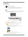
Connections
Connecting a Computer
Using a Power cord with Earth
•
In the event of failure, the earth lead may cause electric shock. Make sure to
wire the earth lead in correctly, before connecting the AC power. When unwiring the earth lead, make sure to disconnect the AC power in advance.
Note
AV input devices such as DVD players, VCR's or camcorders as well as your computer can be connected to the LCD Display. For detailed information on connecting AV input devices, refer to the User
Controls under Adjusting Your LCD Display.
Connect the power cord for your LCD Display to the power port on the back of
the LCD Display. Trun on the power switch.
There are 3 ways to connect the D-sub to your LCD Display. Choose one of the
following:
Using the D-sub (Analog) connector on the video card.
•
Connect the D-sub to the 15-pin, RGB port on the back of your LCD Display
and the 15 pin D-sub Port on the computer.
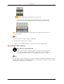
Using the DVI (Digital) connector on the video card.
•
Connect the DVI Cable to the DVI(HDCP) port on the back of your LCD
Display and the DVI port on the computer.
Connections
Using the BNC (Analog) connector on the video card.
•
Connect the BNC Cable to the BNC/COMPONENT IN - R, G, B, H, V ports
on the back of your LCD Display and the 15 pin D-sub Port on the computer.
Connect the audio cable for your LCD Display to the audio port on the back of
your computer.
Note
•
Turn on both your computer and the LCD Display.
•
The DVI cable or BNC cable is optional.
•
Contact a local SAMSUNG Electronics Service Center to buy optional items.
Connecting to Other devices
Using a Power cord with Earth
•
In the event of failure, the earth lead may cause electric shock. Make sure to
wire the earth lead in correctly, before connecting the AC power. When unwiring the earth lead, make sure to disconnect the AC power in advance.
Note
AV input devices such as DVD players, VCR's or camcorders as well as your computer can be connected to the LCD Display. For detailed information on connecting AV input devices, refer to the User
Controls under Adjusting Your LCD Display.
Connections
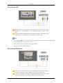
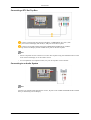
Connecting a VCR
AV input devices such as VCRs or Camcorders are connected via the AV IN
[VIDEO] or AV IN [S-VIDEO] of the LCD Display using an S-VHS or BNC
cable.
Connect the Audio (L) and Audio (R) terminals of a VCR or Camcorders to the
LCD Display 's AV AUDIO IN [L-AUDIO-R] using audio cables.
Note
•
Select AV or S-Video for a connected VCR or Camcorder using the SOURCE button on the front
of the LCD Display or on the remote control.
•
Then, start the VCR or Camcorders with a tape inserted.
•
The S-VHS or BNC cable is optional.
Connecting a DVD Player
Connect a set of audio cables between the COMPONENT AUDIO IN [L-AUDIOR] on the LCD Display and the AUDIO OUT jacks on the DVD player.
Connect a Component cable between the BNC/COMPONENT IN - PR, Y, PB
port on the LCD Display and the PR, Y, PB jacks on the DVD player.
Connections
Note
•
Select Component for the connection to a DVD player using the SOURCE button on the front of
the LCD Display or on the remote control.
•
Then, start the DVD Player with a DVD disc inserted.
•
A component cable is optional.
•
For an explanation of Component video, consult your DVD manual.
Connecting a Camcorder
Locate the A/V output jacks on the camcorder. They are usually found on the side
or back of the camcorder. Connect a set of audio cables between the AUDIO
OUTPUT jacks on the camcorder and the AV AUDIO IN [L-AUDIO-R] on the
LCD Display.
Connect a video cable between the VIDEO OUTPUT jack on the camcorder and
the AV IN [VIDEO] on the LCD Display.
Note
•
Select AV for the Camcorder connection using the SOURCE button on the front of the LCD Display
or on the remote control.
•
Then, start the Camcorders with a tape inserted.
•
The audio-video cables shown here are usually included with a Camcorder.
(If not, check your local electronics store.)
•
If your camcorder is stereo, you need to connect a set of two cables.
Connections
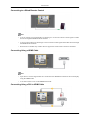
Connecting a DTV Set Top Box
Connect a Component cable between the BNC / COMPONENT IN - PR, Y, PB
port on the LCD Display and the PR, Y, PB jacks on the Set Top Box.
Connect a set of audio cables between the COMPONENT AUDIO IN [L-AUDIOR] on the LCD Display and the AUDIO OUT jacks on the Set Top Box.
Note
•
Select Component for the connection to a DTV Set Top Box using the SOURCE button on the
front of the LCD Display or on the remote control.
•
For an explanation of Component video, see your Set Top Box owner's manual.
Connecting to an Audio System
Note
Connect a set of audio cables between the AUX L, R jacks on the AUDIO SYSTEM and the AUDIO
OUT [L-AUDIO-R] on LCD Display.
Connections
Connecting to a Wired Remote Control
Note
•
You can control your LCD Display by allowing it to receive the remote control signals of other
devices through the REMOTE OUT terminal.
•
You can control a device by allowing it to receive remote control signals from other devices through
the REMOTE IN terminal.
•
Restrictions: Available only if other devices support the wired remote control I/O terminals.
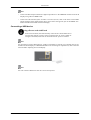
Connecting Using a HDMI Cable
Note
•
Input devices such as digital DVD are connected to the HDMI IN terminal of the LCD Display
using the HDMI cable.
•
You cannot connect a PC to the HDMI IN terminal.
Connecting Using a DVI to HDMI Cable
Connections
Note
•
Connect the DVI output terminal of a digital output device to the HDMI IN terminal of the LCD
Display using a DVI to HDMI cable.
•
Connect the red and white jacks of an RCA to stereo (for PC) cable to the same colored audio
output terminals of the digital output device, and connect the opposite jack to the HDMI / PC /
DVI-D AUDIO IN terminal of the LCD Display.
Connecting a USB device
Using a Power cord with Earth
•
In the event of failure, the earth lead may cause electric shock. Make sure to
wire the earth lead in correctly, before connecting the AC power. When unwiring the earth lead, make sure to disconnect the AC power in advance.
Note
AV input devices such as DVD players, VCR's or camcorders as well as your computer can be connected to the LCD Display. For detailed information on connecting AV input devices, refer to the User
Controls under Adjusting Your LCD Display.
Note
You can connect USB devices such as a mouse or keyboard.
Troubleshooting
Self-Test Feature Check
Note
Check the following items yourself before calling for assistance. Contact a Service Center for problems
that you cannot solve by yourself.
Self-Test Feature Check
1.
Turn off both your computer and the LCD Display.
2.
Unplug the video cable from the back of the computer.
3.
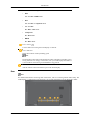
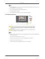
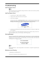
Turn on the LCD Display.
The figure shown below ("Check Signal Cable") appears on a black background when the LCD
Display is working normally even though no video signal is detected: While in the Self-Test mode,
the LED power indicator remains green and the figure moves around on the screen.
4.
Turn off your LCD Display and reconnect the video cable; then turn on both your computer and
the LCD Display
If your LCD Display screen remains blank after using the previous procedure, check your video controller and computer system; your LCD Display is functioning properly.
Warning Messages
You can even view the screen at a resolution of 1360 x 768. However, you will receive the following
message for a minute; You can choose to change the screen resolution or stay in the current mode
during that time. And if the resolution is more than 85Hz, you will see the black screen because the
LCD Display does not support over 85Hz.
Note
Refer to Specifications > Preset Timing Modes for the resolutions or frequencies supported by the
LCD Display.
Maintenance and Cleaning
1) Maintaining the LCD Display Case.
Clean with a soft cloth after disconnecting the power cord.
Troubleshooting
•
Do not use benzene, thinner or other flammable substances, or a wet cloth.
•
We recommend that a SAMSUNG cleansing agent is used
to prevent damage to the screen.
2) Maintaining the Flat Panel Display Screen.
Clean with a soft cloth (cotton flannel) smoothly.
•
Never use acetone, benzene or thinner.
(They may cause flaws or deformation of the screen surface.)
•
The user will be required to pay costs and related expenses
for repairing damages caused.
Symptoms and Recommended Actions
Note
A LCD Display recreates visual signals received from the computer. Therefore, if there is a problem
with the computer or the video card, this can cause the LCD Display to become blank, have poor
coloring, become noisy, and video mode not supported, etc. In this case, first check the source of the
problem, and then contact a Service Center or your dealer.
1.
Check if the power cord and the video cables are properly connected to the computer.
2.
Check if the computer beeps more than 3 times when booting.
(If it does, request an a service for the main board of the computer.)
3.
If you installed a new video card or if you assembled the PC, check if you installed the Adaptor
(video).
4.
Check if the scanning ratio of the video screen is set to between 50 Hz ~ 85 Hz.
(Do not exceed 60Hz when using the maximum resolution.)
5.
If you have problems in installing the Adaptor (video) driver, boot the computer in Safe Mode,
remove the Display Adaptor in the "Control Panel → System → Device Administrator" and then
reboot the computer to reinstall the Adaptor (video) driver.
Check List
Note
•
The following table lists possible problems and their solutions. Before calling for assistance, check
the information in this section to see if you can remedy any problems for yourself. If you do need
assistance, please call the phone number on the Information section or contact your dealer.
Problems related to the Installation (PC Mode)
Note
Problems related to the LCD Display installation and their solutions are listed.
Q:
The LCD Display screen flickers.
A:
Check if the signal cable between the computer and the LCD Display is securely connected.
Troubleshooting
(Refer to Connecting a Computer)
Problems related to the Screen
Note
Problems related to the LCD Display screen and their solutions are listed.
Q:
The screen is blank and the power indicator is off.
A:
Ensure that the power cord is firmly connected and the LCD Display is on.
(Refer to the Connecting a Computer)
Q:
"Check Signal Cable" message.
A:
Ensure that the signal cable is firmly connected to the PC or video sources.
(Refer to the Connecting a Computer)
A:
Ensure that the PC or video sources are turned on.
Q:
"Not Optimum Mode" message.
A:
Check the maximum resolution and the frequency of the video Adaptor.
A:
Compare these values with the data in the Preset Timing Modes Chart.
Q:
The picture rolls vertically.
A:
Check if the signal cable is securely connected. Re-connect it, if necessary.
(Refer to Connecting a Computer)
Q:
The image is not clear; picture is blurred.
A:
Run Frequency Coarse and Fine tuning.
A:
Turn on again after removing all accessories (video extension cable, etc.)
A:
Set the resolution and frequency to the recommended ranges.
Q:
The picture image is unstable and shakes.
A:
Check if the resolution and frequency set for the computer video card falls in the range supported
by the LCD Display. If not, reset them referring to the current Information under the LCD Display
menu and Preset Timing Modes.
Q:
Ghost images are shown in the picture.
A:
Check if the resolution and frequency set for the computer video card falls in the range supported
by the LCD Display. If not, reset them referring to the current Information under the LCD Display
menu and Preset Timing Modes.
Q:
The image is too light or too dark.
A:
Adjusts the brightness and contrast.
(Refer to the Brightness, Contrast)
Q:
The screen color is inconsistent.
A:
Adjust color using Custom under OSD Color Adjustment menu.
Troubleshooting
Q:
The color image is distorted by dark shadows.
A:
Adjust color using Custom under OSD Color Adjustment menu.
Q:
The color white is poor.
A:
Adjust color using Custom under OSD Color Adjustment menu.
Q:
The power Indicator blinks green.
A:
The LCD Display is currently saving the changes made to the settings to the OSD memory.
Q:
The screen is blank and the power indicator light is steady green or blinks every 0.5 or 1 seconds.
A:
The LCD Display is using its power management system.
A:
Press a key on the keyboard.
Q:
The screen is blank and it is blinking.
A:
If you see the "TEST GOOD" message on the screen when you pressing the MENU button,
check the cable connection between the LCD Display and the computer to ensure that the connector is properly connected.
Problems related to Audio
Note
Problems related to audio signals and their solutions are listed below.
Q:
No sound.
A:
Ensure that the audio cable is firmly connected to both the audio-in port on your LCD Display
and the audio-out port on your sound card.
(Refer to the Connecting a Computer)
A:
Check the volume level.
Q:
The sound level is too low.
A:
Check the volume level.
A:
If the volume is still too low after turning the control to its maximum, check the volume control
on the computer sound card or software program.
Q:
The sound is too high or too low.
A:
Adjusts the Treble and Bass to the appropriate levels.
Problems related to the Remote Control
Note
Problems related to the remote control and their solutions are listed.
Q:
The remote control buttons do not respond.
A:
Check the polarities (+/-) of the batteries.
A:
Check if the batteries are empty.
A:
Check if the power is on.
Troubleshooting
A:
Check if the power cord is securely connected.
A:
Check if a special fluorescent or neon lamp is on in the vicinity.
Q:
How can I change the frequency?
A:
The frequency can be changed by reconfiguring the video card.
Q&A
Note
that video card support can vary, depending on the version of the driver used. (Refer to the
computer or the video card manual for details.)
Q:
How can I Adjusts the resolution?
A:
Windows XP:
Set the resolution in the Control Panel → Appearance and Themes → Display → Settings.
A:
Windows ME/2000:
Set the resolution in the Control Panel → Display → Settings.
* Contact the video card manufacturer for details.
Q:
How can I set the Power Saving function?
A:
Windows XP:
Set the resolution in the Control Panel → Appearance and Themes → Display → Screen Saver.
Set the function in the BIOS-SETUP of the computer. (Refer to the Windows / Computer Manual).
A:
Windows ME/2000:
Set the resolution at the Control Panel → Display → Screen Saver.
Set the function in the BIOS-SETUP of the computer. (Refer to the Windows / Computer Manual).
Q:
How can I clean the outer case/LCD Panel?
A:
Disconnect the power cord and then clean the LCD Display with a soft cloth, using either a
cleaning solution or plain water.
Do not leave any detergent or scratches on the case. Do not let any water enter the LCD Display.
Q:
How can I play the video?
A:
The video supports the MPEG1 and WMV codecs only. Install the corresponding codec to play
the video. Note that some of the codecs can be incompatible.
Note
Before calling for assistance, check the information in this section to see if you can remedy any problems yourself. If you do need assistance, please call the phone number on the Information section or
contact your dealer.