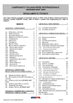
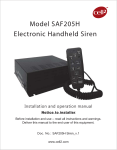
1
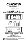
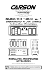
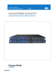
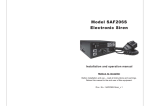
Carson Manufacturing Co., Inc.
5451 North Rural Street
Indianapolis, IN 46220
Phone: (888) 577-6877 Fax: (317) 254-2667
www.carson-mfg.com
HPK-100
HORN SYSTEM
HORN SELECT
V
E
H
LITE
A
I
R
O
F
F
O
N
CSP-100B
NEG
SPK
SPK
POS
100W 11 OHM
INSTALLATION AND OPERATING
INSTRUCTIONS
This product is legal in most states.
Please consult your state/local vehicle codes to ensure compliance with vehicle horn regulations.
Carson is a trademark of Carson Manufacturing Company, Inc.
Sound Hazard - Sound level from horn speaker (>120dBA @ 10 feet) may cause hearing damage.
Do not operate horn without adequate hearing protection for you and anyone in immediate vicinity.
(Ref. OSHA 1910.95 for occupational noise exposure guidelines)
Page 2 of 8
HPK-100 Installation and Operating Instructions
GENERAL DESCRIPTION
The HPK-100 is a complete electronic simulated air-horn system. The system includes an amplifier with matching speaker along with a switch panel. The switch panel allows changing between
the vehicle horn and air-horn and includes a switch for emergency lighting. The amplifier utilizes
short circuit, high voltage, and reverse polarity protection systems for maximum service life. An
output indicator light is provided on the amplifier for diagnostics.
SPECIFICATIONS
Amplifier (HA-100-10 14)
Speaker Load
Single 100W 11 ohm
Input Voltage
9 - 16 VDC (negative ground)
Input Current
Output Power
High Voltage Protection
8 AMPS (14 VDC)
105 WATTS RMS MAX. (15 VDC)
16 - 18 VDC will cause siren output to cease, resume at normal
Short Circuit Current
50 AMPS (supply circuit must be capable of supplying this for 1 second)
Operating Temp.
Size
-15° F to +140°F
3-5/8" Long, 4-1/4" Wide, 1-13/16" High
Weight
1 LB.
Speaker (CSP-100B)
Power Handling
100W
Impedance
11 ohm nominal
Frequency Range
400 Hz to 3500 Hz
Size
6.34” Wide, 5.10” High, 2.36” Deep
Weight
6 LBS.
Switch Panel (SP-200)
Voltage
12VDC
Current
15ADC Max.
Size
3-3/4” Wide, 1-1/4” High, 1-3/4” Deep
NOTICE
Due to continuous product improvements, we must reserve the right to change any specifications and information,
contained in this manual at any time without notice.
Carson Manufacturing Co., Inc. makes no warranty of any kind with regard to this manual, including, but not
limited to, the implied warranties of merchantability and fitness for a particular purpose.
Carson Manufacturing Co., Inc. shall not be liable for errors contained herein or for incidental or consequential
damages in connection with the furnishing, performance, or use of this manual.
See www.carson-mfg.com for latest information.
02/04/10
CP5060A
HPK-100 Installation and Operating Instructions
Page 3 of 8
INSTALLATION
Proper installation of the system is essential for years of safe, reliable operation. Please read all
instruction before installing the system components. Failure to follow these instructions can
cause serious damage to the components or vehicle and may void warranties.
SAFETY PRECAUTIONS
For the safety of the installer, vehicle operator, passengers and the community please observe
the following safety precautions. Failure to follow all safety precautions and instructions may
result in property damage, injury or death.
Qualifications - The installer must have a firm knowledge of basic electricity, vehicle electrical
systems and emergency equipment.
Sound Hazard - Sound level from horn speaker (>120dBA @ 10 feet) may cause hearing damage.
Do not operate horn without adequate hearing protection for you and anyone in immediate vicinity.
(Ref. OSHA 1910.95 for occupational noise exposure guidelines)
Mounting - Mount the unit for easy access by the vehicle operator. DO NOT mount in air bag
deployment area. Assure clearances before drilling in vehicle.
Wiring - Use wiring capable of handling the current required. Make sure all connections are tight.
Route wiring to prevent wear, overheating and interference with air bag deployment. Install and
check all wiring before connection to vehicle battery.
Testing - Test all horn system functions after installation to assure proper operation. Test vehicle
operation to assure no damage to vehicle.
Keep These Instructions - Keep these instructions in the vehicle or other safe place for future
reference. Advise the vehicle operator of the location.
UNPACKING
Inspect contents for shipping damage. If found alert carrier immediately.
Contact supplier immediately if any components are missing.
Contents of box should include the following items:
Qty Item
1 Amplifier Unit (HA-100-10 14)
1
Speaker, 100W 11 ohm (CSP-100B)
1
Switch Panel (SP-200)
1
Connector, 4-P Terminal Block Plug (CP4688-04)
6
Screw, Hex #8 Self Drilling (CP4051-XK-12)
6
Terminal, 3/16” Insulated Fem. Q.C. (CP4062-K2545)
1
Instruction Manual (CP5060 This Manual)
CP5060A
02/04/10
Page 4 of 8
HPK-100 Installation and Operating Instructions
MOUNTING
Amplifier
Select a location for the amplifier in an area such as the driver compartment firewall, under a seat,
etc. Mounting the amplifier in the engine compartment or in an area directly exposed to weather
is not recommended. Allow clearance for wiring. Inspect behind mounting area for clearance.
Install the terminal block plug and make all electrical connections before final mounting. Use #8
screws (supplied loose) for mounting.
Speaker
The speaker is weather resistant and is intended to be mounted on the outside of the vehicle or
under front hood. Mount the speaker facing forward and as far forward on the vehicle as possible
to minimize sound exposure to occupants. Choose a location that minimizes obstructions in front
of the speaker to maximize forward sound. Attach the speaker to a sturdy part of the vehicle to
prevent vibration and possible damage. Attach the speaker angled slightly toward the road so the
front openings will drain off any fluids. Cover openings of speaker while drilling any holes.
DO NOT get metal shavings inside the speaker.
Switch Panel
Mount the switch panel underneath the vehicle dash board using #8 screws (supplied loose).
Locate the panel away from the driver’s or passenger’s legs. Allow clearance for wiring. Inspect
behind mounting area for clearance. Make all electrical connections before final mounting.
ELECTRICAL CONNECTIONS
Amplifier
Electrical connections to the amplifier are made using a removable terminal block plug (supplied
loose) located on the side. A label on the amplifier identifies each terminal function. You should
install the plug on the amplifier before wiring. If the unit needs service the plug can be easily
removed without unwiring. The amplifier is fused near the connector. The power supply for the
amplifier must be capable of delivering peak currents up to 50 amps for adequate short circuit
protection and reliable operation. Most vehicle horn circuits with relays provide adequate power
on the vehicle horn side of the relay. However do not provide power to both the vehicle horn and
this amplifier from one horn relay circuit as this will exceed circuit rating.
NOTE: Permanent disconnection of the vehicle horn is NOT recommended.
Attach leads by stripping 3/8", inserting into plug and clamp by tightening screw. Make sure the
screw is tight and the wire can't be pulled out. Failure to adequately tighten the screw can
result in improper operation or burning the connector and wire.
Switch Panel
Electrical connections to the switch panel are made using 3/16” quick-connect terminals (supplied
loose).
Wire Size and Termination - The diagram shows the minimum wire size used for each connection, along with recommended lead color. If the wire is longer than 10 ft. use the next larger wire
size. Use only high quality crimp connectors for installation on the vehicle.
02/04/10
CP5060A
HPK-100 Installation and Operating Instructions
Page 5 of 8
ELECTRICAL CONNECTIONS CONTINUED
NOTE: Permanent disconnection of the vehicle horn is NOT recommended.
LITE
SWITCH
BLK #22G -VDC FOR LAMP
12V
LAMP
ADD PROPER FUSE
20A MAX.
Recommended
Wire Size
Amps
Size
5 - 10
#16G
10 - 15
#14G
Use next larger
size
if longer than 10 ft.
RED +VDC IN
RATED 15A @ 12VDC
YEL +VDC OUT
Lite
OBSERVE
SWITCH TERMINAL
SPACING FOR
ORIENTATION
SEE
WIRE SIZE TABLE
UNDER HOOD
ORG or RED #16G
HORN SELECT
SWITCH
+VDC
HORN
RELAY
CIRCUIT
RATED 15A @ 12VDC
HORN
RELAY
Splice
OBSERVE
SWITCH TERMINAL
SPACING FOR
ORIENTATION
GRN #16G
Break
Connection
Splice
BLU #16G
If the “HORN RELAY CIRCUIT” provides -VDC:
Connect “ORG or RED #16G” wire to +VDC supply
and connect “#16G BLK” to “HORN SELECT SWITCH”.
Vehicle
Horn
ORG or RED #16G
CSP-100B
SPEAKER
100W 11 ohm
#16G BLK to -VDC
Splice
#18G BRN
#18G BRN
4-P Terminal Block Plug
(CP4688-04)
Splice
Plug installed
this orientation
15A Automotive
Type Fuse
USE
WATERPROOF
BUTT CONNECTORS
FOR UNDER HOOD SPLICES
NEG
SPK
SPK
POS
Plug into unit first for
terminal identification
#18G BRN
#18G WHT
CP5060A
02/04/10
Page 6 of 8
HPK-100 Installation and Operating Instructions
ELECTRICAL CONNECTIONS CONTINUED
(NOT USING SWITCH PANEL)
NOTE: Permanent disconnection of the vehicle horn is NOT recommended.
Amplifier Power
Connection Examples
+VDC
Vehicle
Horn
+VDC
Added
SPDT
Switch
Vehicle
Horn
To
Amp POS
To Amp POS
Horn
Circuit
Splice
+VDC
Assumes Power is +VDC
May be powered with
-VDC instead, just change
to -VDC and Amp NEG in
diagrams.
HORN RLY
Momentary
SPST
Switch
Added
Relay
Note:
Vehicle horn
To Amp POS will also sound
#16G RED to +VDC
#16G BLK to -VDC
#18G BRN
#18G BRN
4-P Terminal Block Plug
(CP4688-04)
Plug installed
this orientation
15A Automotive
Type Fuse
NEG
SPK
SPK
POS
Plug into unit first for
terminal identification
OPERATION
Sound Hazard - Sound level from horn speaker (>120dBA @ 10 feet) may cause hearing damage.
Do not operate horn without adequate hearing protection for you and anyone in immediate vicinity.
(Ref. OSHA 1910.95 for occupational noise exposure guidelines)
USING SWITCH PANEL
In an emergency situation, set the HORN SELECT switch to AIR and turn on the LITE switch in
one sweeping motion. When the horn ring on the vehicle is pressed the amplifier and speaker
produce a simulated air horn sound. An output indicator on the side of the amplifier also lights up.
The output indicator is located opposite the end with connector.
When the emergency is over, turn off the LITE switch and set the HORN SELECT switch to VEH
in one sweeping motion. When the horn ring is pressed the regular vehicle horn will sound.
NOT USING SWITCH PANEL
As soon as power is applied, the amplifier and speaker produce a simulated air horn sound and
the output indicator lights up. The output indicator is located opposite the end with connector.
02/04/10
CP5060A
HPK-100 Installation and Operating Instructions
Page 7 of 8
SERVICE
The complete system consists of the amplifier, speaker, and switch panel components along with
the wiring and electrical connections. A blown fuse on the amplifier does not necessarily
mean the amplifier is bad. If the system stops functioning or exhibits problems, first check that
the wire and electrical connections to each component are OK then check the following.
On the switch panel, check for power into (center terminal) and out of the switch. On the HORN
SELECT switch, check for power while pressing the horn ring. If there is not power into the
switch, check wire for bad connections and check fuses or breakers in the circuit. If there is
power into but not out of the switch, the switch itself may be bad.
While activating the amplifier (with horn ring), look for the output indicator to light up. If it
lights up the amplifier is OK. If not, check the fuse on the amplifier. If the fuse is OK then check
the POS and NEG power input leads for good supply and ground connections. If power into the
amplifier is OK then check that the voltage level at POS and NEG on the amplifier is less than the
rated voltage. If the voltage level is OK then the amplifier may be bad.
If the fuse on the amplifier is blown, disconnect the speaker leads at the amplifier and replace
the fuse. As before, activate the amplifier and look for the output indicator to light up. If the fuse
blows again then the amplifier may be bad.
If the output indicator on the amplifier lights up, disconnect the leads at the speaker and
check the speaker inputs with an ohm meter. If the reading is less than 1 ohm or reads as open
circuit then the speaker may be bad. If the ohm meter reading is OK then the wiring or connections between the amplifier and speaker may be faulty.
The following chart shows typical symptoms and possible causes.
PROBLEMS
Symptom
No power or
output
Distorted sound
Intermittent tone
Possible Cause
Power not applied
Connector loose
Fuse blown
Loose connection at power source
High Voltage Protection
Bad speaker
Speaker assembly loose
Low vehicle voltage
High Voltage Protection
Connector loose
Bad power connection
Circuit breaker in supply connection
Check
Is the output indicator light coming on?
Is an external fuse or circuit breaker used?
Are the negative leads connected to a good ground?
Input voltage must be less than highest rated voltage.
Try another speaker.
Is the speaker bell or tip loose?
Input voltage must be greater than lowest rated voltage.
Is the vehicle voltage regulator working properly?
Is the connector tight on the unit?
Is there a loose connection on a power lead?
Is a circuit breaker used with at least a 50A rating?
PARTS and ACCESSORIES
The following parts and accessories are available from Carson Manufacturing Company, Inc.:
Part
CP5030
CP4990-150
CP4993
CP5044-2
CP4998
Description
Cover, (not including chassis) (for amplifier)
Fuse, 15 Amp Mini Automotive (for amplifier)
Switch, Lighted Rocker (Lite switch on panel)
Switch, Red Rocker ON - ON (Horn Select switch on panel)
Transistor, output (2 required) (for amplifier)
Accessory
ED1914
ED1924
CP4688-04 *
CP4051-XK-12 *
CP4062-K2545 *
CP5060 *
Description
* - standard accessory supplied with unit
Cable, 4-P Lead Assembly 15FT (made w/ CP4688-04 Conn) (for amplifier)
Cable, 6-P Lead Assembly 15FT (made w/ 3/16” Q.C. Terminals) (for switch panel)
Connector, 4-P Terminal Block Plug (for amplifier)
Screw, Hex #8 Self Drilling (for mounting)
Terminal, 3/16” Insulated Fem. Q.C. (for switch panel)
Manual, HPK-100 Instruction
CP5060A
02/04/10
Page 8 of 8
HPK-100 Installation and Operating Instructions
See www.carson-mfg.com for additional information.
or contact our Service Department at:
E-mail [email protected] or Phone (888) 577-6877
RETURN
If you have any questions concerning this or any other Carson product,
please contact our Technical Service Department at (888) 577-6877.
Many issues can be handled over the phone. We can also be reached via
e-mail at [email protected]
If a product must be returned for any reason, please contact our Technical
Service Department to obtain a Returned Merchandise Authorization number (RMA#) before you ship the product to Carson. Please write the RMA#
clearly on the package near the mailing label. Be sure to provide a return
address, contact and phone number, along with a brief description of the
problem.
LIMITED WARRANTY
Carson Manufacturing Company, Inc. warrants this new product to be free from defects
in material and workmanship, under normal use and service, for a period of five (5)
years from the date of delivery to the first user-purchaser.
During this warranty period the obligation of Carson Manufacturing is limited to repairing
or replacing, as Carson Manufacturing may elect, any part or parts of such product
which after examination by Carson Manufacturing is determined to be defective in material and/or workmanship.
This warranty does not cover labor charges for removal or re-installation of the product.
Fuses and lamps and speakers are not covered under this warranty.
This warranty does not extend to any unit that has been subjected to abuse, misuse,
improper installation or which has not been adequately maintained, nor to units which
have problems related to service or modification at any facility other than the manufacturer.
THERE ARE NO OTHER WARRANTIES, EXPRESSED OR IMPLIED, INCLUDING
BUT NOT LIMITED TO, ANY IMPLIED WARRANTIES OF MERCHANTABILITY OR
FITNESS FOR A PARTICULAR PURPOSE. IN NO EVENT SHALL CARSON MANUFACTURING COMPANY, INC. BE LIABLE FOR ANY LOSS OF PROFITS OR ANY
INDIRECT OR CONSEQUENTIAL DAMAGES ARISING OUT OF ANY SUCH DEFECT
IN MATERIALS OR WORKMANSHIP.
02/04/10
CP5060A