1
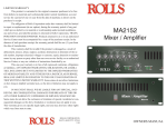
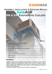
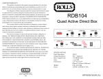
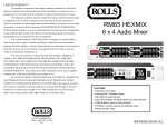
SPECIFICATIONS
Power Output, Stereo:
Input Connectors:
Output Connectors:
Sensitivity:
THD:
S/N Ratio:
Power Bandwidth:
Damping Factor:
Slew Rate:
Phase Shift:
Input Impedance:
Power:
Size:
Weight:
100 Watts RMS/ch. 4 Ω
70 Watts RMS/ch. 8 Ω
Bridged - 200 Watts RMS or 70 Volt 8 Ω
1/4" TRS balanced and RCA
1/4" and 5-way binding posts
<1 VRMS for full output
<.08% (1kHz @ 1 Watt)
106 dBU
50 Hz - 25 kHz, +/- 1 dB
> 150
100 Volts/microSecond
<10 Deg., 20Hz - 20kHz
10 KΩ Balanced
120 VAC 60Hz 2.5A
230 VAC 50Hz
19” x 3.5” x 7.5”
(48 x 9 x 19 cm)
12 lbs (5.5 kg)
RA2100b Power Amplifer
100 WATT STEREO - 200 WATT BRIDGED
70 VOLT BRIDGED
LIMITED WARRANTY
This product is warranted to the original consumer purchaser to be free from defects in
materials and workmanship under normal installation, use and service for a period of one (1) year
from the date of purchase as shown on the purchaser’s receipt.
The obligation of Rolls Corporation under this warranty shall be limited to repair or
replacement (at our option), during the warranty period of any part which proves defective in
material or workmanship under normal installation, use and service, provided the product is
returned to Rolls Corporation, TRANSPORTATION CHARGES PREPAID. Products returned to
us or to an authorized Service Center must be accompanied by a copy of the purchase receipt. In
the absence of such purchase receipt, the warranty period shall be one (1) year from the date of
manufacture.
This warranty shall be invalid if the product is damaged as a result of defacement,
misuse, abuse, neglect, accident, destruction or alteration of the serial number, improper electrical
voltages or currents, repair, alteration or maintenance by any person or party other than our own
service facility or an authorized Service Center, or any use violative of instructions furnished by us.
This one-year warranty is in lieu of all expressed warranties, obligations or liabilities.
ANY IMPLIED WARRANTIES, OBLIGATIONS, OR LIABILITIES, INCLUDING BUT NOT
LIMITED TO THE IMPLIED WARRANTIES OF MERCHANTABILITY AND FITNESS FOR A
PARTICULAR PURPOSE, SHALL BE LIMITED IN DURATION TO THE ONE YEAR
DURATION OF THIS WRITTEN LIMITED WARRANTY. Some states do not allow limitations
on how long an implied warranty lasts, so the above limitation may not apply to you.
IN NO EVENT SHALL WE BE LIABLE FOR ANY SPECIAL, INCIDENTAL OR
CONSEQUENTIAL DAMAGES FOR BREACH OF THIS OR ANY OTHER WARRANTY,
EXPRESSED OR IMPLIED, WHATSOEVER. Some states do not allow the exclusion or
limitation of special, incidental or consequential damages so the above limitation or exclusion may
not apply to you. This warranty gives you specific legal rights, and you may also have other rights
which vary from state to state.
ROLLS CORPORATION
SALT LAKE CITY, UTAH
7/00
VOLUME 1
0
10
VOLUME 2
1
5 30 100
WATTS 4 Ohms
CT
POWER
RA2100b
0
10
1
5 30 100
PROTEC
WATTS 4 Ohms
MOSFET POWER
AMPLIFIER
OWNERS MANUAL
INTRODUCTION
Thank you for your purchase of the ROLLS RA2100b Power Amplifier. The
RA2100b is a stereo 100W/channel RMS power amplifier in a standard 2 rack
space format. It is intended for professional audio and distributed musical applications. The unit features 100 Watts per channel RMS into four ohms, 85 Watts per
channel into eight ohms, and for the contractor - 70 Volts / eight ohms.
The unit also features MOSFET drivers in a voltage and current gain circuit, a
one-second input turn-on delay, and LED power output meters. The RA2100b will
drive 25 Volt speaker lines directly from each channel, or 70 Volt lines bridged.
whenever the output stage is called upon for too much power, it may also be
fooled by impedances lower than four ohms - which may cause the output stage
to overheat and burn up the MOSFETs.
Since the RA2100b is convection cooled, the unit radiates heat from the rear
panel and , depending on the load demand, it may become very hot if drawn upon
heavily.
INSPECTION
1. Unpack and inspect the RA2100b box and package.
If obvious physical damage is noticed, contact the carrier immediately to make a
damage claim. We suggest saving the shipping carton and packing materials for
safely transporting the unit in the future.
DRIVING 25 OR 70 VOLT LINES
The RA2100b will drive 25 or 70 Volt lines directly with no added transformers
when used the following way:
• Each channel will drive 25 volt lines directly.
• A single 70 volt line may be driven when the RA2100b is in Bridged mode. In
order to drive two 70 volt lines, two 8 ohms to 70 Volt conversion transformers will
be needed.
2. Please complete the Warranty Registration Card and return it to the factory.
SCHEMATIC
R 5
3 3 K
C H A N N E L 1
R 9
1 0 K
L o C u t
C 1
.0 0 1
1 4 5 8
R 8
4 7 0
Vr-
3
8
C 4
Q 1
C 1 7
1 U
1
OUTPUT 1
BRIDGE NORMAL
1
5
8
P 1 0 1
R 4 6
3 3 K
R 4 8
1 K
P 1 0 0 K
D 2 6
To reduce the risk of electric
shock or fire do not expose
this device to rain or moisture.
R 8 7
4 7 K
R 8 8
4 7 K
1 N 4 1 4 8
Vr+
1 0 K
D 2 4
L D R R
P R O T E C T
FAULT PROTECTION
The fault protection in the RA2100b limits the current to the output stage in the
faulted channel and turns on all the LEDs in that channel. This mode is entered
Q 2 9
2 N 3 9 0 4
1 K
4 A M P
J 3
2
P 1 0 2
B R ID G E
5 0 0
P 1 0 2 F O R 1 - 2 m V A C R O S S R 1 1 A N D R 1 1 1
S E T P 2 A N D
.1
2 N 3 9 0 6
Q 1 7
R 6 2
4 7 0
D 1 1
R 6 3
R 6 5
S W
S P S T
5 0 3
C P 8 0 1 0
2
B R 1
1
R 9 3
3 .3 K
3
V-
A C M A L E
M A IN S T R A N S F O R M E R
1 0 K
D 2 2
1 0 K
Z D 1 2 V
R 6 7
1 0 K
D 1 6
V+
1 N 4 1 4 8
C 1 2
R 8 1
1 0 K
.0 0 2
R 7 2
1
Z D 1 2 V
1 2 V
L A S T R 7 2 C 1 5
F 4
V- 6 A
3 2
Q 2 8
D 2 0
L D R R
1 0 0
R 8 5
3 3 K
D 1 3
1 N 4 1 4 8
R 7 6
D 1 9
L D R G
2 N 3 9 0 4
R 8 4
1 0 0 K
V+
VrQ 2 4
2 N 3 9 0 4
5
Q 2 7
2 N 3 9 0 4
Q 2 2
2 N 3 9 0 6
D 1 8
L D R G
2 N 3 9 0 4
H E A T S IN K
R 7 4
1 0 K
D 1 7
L D R Y
Q 2 6
R 8 0
1 0 0 K
R 8 3
1 0 K
5 1
R 7 3
2 2 K
1 K
-1 2 V
Q 3 2
Q 2 3
IR F 5 4 0
R 7 5
R 1 0 0
4 .7 K
Q 2 5
2 N 3 9 0 4
R 7 9
1 0 K
5 1
R 7 0
1 0 0
2 K
D 1 2
1 N 4 1 4 8
1 0 U
D 2 3
C 1 5
1 0 U
D 1 5
1 N 4 1 4 8
Q 2 0
IR F 9 5 4 0
Q 1 9
2 N 3 9 0 4
Q 2 1
M P S A 5 6
C 1 6
2 N 3 9 0 6
R 9 6
D 1 4
1 N 4 1 4 8
R 6 8
R 7 1
2 N 3 9 0 4
R 9 9
D 2 1
R E D
R 9 5
1 K
C 1 4
6 8 0 0 U F
1 0 0
H E A T S IN K
R 7 8
1 0 K
R 6 4
3 3 0
R 6 0
4 7 K
Vr+
D 1 0
L D R R
R 4 2
3 3 K
H D 4
R 8 2
1 0 0 K
Q 3 1
3 2
Q 1 4
2 N 3 9 0 4
1 K
R 6 9
3 3 0
Vr-
1 K
C 1 3
6 8 0 0 U F R 9 4
2 2 K
C 1 8
T 1
R 9 8
D 9
L D R G
R 3 4
Q 9
2 N 3 9 0 6
R 6 6
2 2 K
2 K
Q 1 8
M P S A 0 6
4 7 K
R 5 8
1 0 K
VrS W 1
F 5
R 3 2
1 K
R 5 7
1 5 0
V+
R 4 1
1 0 0 K
IR F 5 4 0
R 3 3
1 0 K
1 N 4 1 4 8
R 5 9
Q 1 6
2 N 3 9 0 4
R 5 6
1 K
R 9 2
1 0 K
t
T H E R M IS T O R
P L U G
F 3
R 5 5
6 .8 K
5
Q 3 0
2 N 3 9 0 4
R 8 9
1 K
R 1 0 1
R 6 1
6 A
C 1 0
1 2 0 P F
2 N 3 9 0 4
Q 1 3
5 1
4 7 0
R 3 1
.1
6 A
V-
R 5 3
1 K
R 4 9
1 0 0 K
H ? A
H C N 2
Q 1 0
R 2 9
2 2 K
5
V +
6
R 9 0
R 9 1
BRIDGING
To bridge the RA2100b, first ensure the power is off. Move the Bridging switch to
the “Bridge” position. The Channel 1 Volume control will be the master volume,
Channel two Volume is inactive.
Connect the input to Channel 1 input, then connect the load (speakers) to the two
positive (red) banana jacks. Make no connections to the black posts. The level
meters will both light, and the output power into 8 ohms is the sum of the LEDs
that light.
N O R M A L
H 1 A
H 1 B
H ? A
H C N 2
S W 2 B
D P D T
4
1
Vr-
4 7 0 P F
Vr+
R 5 4
1 0 K
7
U 2 B
4
D 8
L D R G
V+
R 3 0
F 2
5 0 P F
Vr+
5
R 2 8
2 K
D 3
1 N 4 1 4 8
3
2 N 3 9 0 4
R 4 0
1 0 K
H 4 B
H D 4
H 4 C
H D 4
H 4 D
H D 4
2
R 2 7
1 0 0
Q 8
M P S A 5 6
R 1 7
4 7 K
Q 7
2 N 3 9 0 4
6
C 9
.0 1
WARNING:
CHANNEL 1 INPUT
R 5 2
1 0 K
1 4 5 8
OUTPUT 2
RISQUE DE CHOC - NE PAS ENLEVER
1
U 2 A
3
1
+
R 1 5
1 0 K
1
Q 1 2
R 3 9
1 0 0 K
1
V r -
D 7
L D R Y
R 3 7
1 0 0 K
H 4 A
.0 0 2
R 2 6
3 3 0
R 1 4
1 5 0
R 1 0 2
Q 1 1 4 .7 K
2 N 3 9 0 4
R 3 5
1 0 K
R 3 8
1 0 K
C 6
R 2 5
3 3 0
1 N 4 1 4 8
C 1 1
2
C 8
1
WARNING
For continued protection against
risk of fire, replace only with
same type and rating of fuse.
TO REDUCE THE RISK OF ELECTRIC
SHOCK DO NOT NOT REMOVE LID. NO
USER SERVICABLE PARTS INSIDE.
REFER SERVICING TO QUALIFIED
SERVICE PERSONNEL
R 5 1
1 0 K
R 5 0
4 7 0
4
MAINS POWER
R 4 4
1 0 K
CAUTION
Q 1 5
J 1 1 3
L o C u t
1 4 5 8
R 2 3
2 2 K
2 N 3 9 0 4
R 1 3
1 K
S W 2 A
D P D T
H ? A
H C N 2
3
J 2
CHANNEL 2 INPUT
C 7
.0 0 1
2
R 4 3
1 0 K
MADE IN U.S.A.
+
R 4 5
1 K
C H A N N E L 2
C O R P O R A T IO N
OUTPUT 1
1
-
R 3 6
1 0 K
5 1
D 2
Q 2
H 1 E
R 4 7
3 3 K
Q 5
2 N 3 9 0 4
R 2 4
V+
D 6
1 N 4 1 4 8
R 1 6
5 0 0
2
2
4
SERIAL NUMBER
R 2 0
1 K
1 N 4 1 4 8
4 7 K
P 2
H ? A
H C N 2
3
R 1 0 4
1 M
3
OUTPUT 2
R 1 2
6 .8 K
1
D 2 5
1 N 4 1 4 8
Vr-
4A 120V - 2A 230 V
R 1 9
D 1
D 5
1 N 4 1 4 18 N 4 1 4 8
Q 6
IR F 9 5 4 0
Q 4
M P S A 0 6
R 1 0 3
1 M
R 1 0 5
R 2 1
1 0 K
4 7 0
Q 3
1 K
2 N 3 9 0 6
1
1 M
.1
R 2 2
2 K
H 1 D
J 4 B
R C A X 2
R 1 8
R 7
1 0 0 K
1 2 0 P F
J 1 1 3
Vr+
J 4 A
R C A X 2
R 1 0
7
U 1 B
F 1
6 A
R 1 1
1 0 K
1 4 5 8
6
5
R 3
1 K
5 0 P F
Vr+
R 6
1 K
R 4
3 3 K
V+
V r +
P 1
P 1 0 0 K
C 3
.0 1
4
C 2
4 7 0 P F
D 4
C 5
4
R 2
1 0 K
1
U 1 A
3
2
2
1
R 1
1 0 K
J 1
3
INSTALLATION
Connect the power cord to an AC power source, connect the input to the signal
source and to the RA2100b via the RCA or 1/4” input jacks. Speakers may be
connected by using the 1/4” output jacks, or the dual banana posts. Turn the
Volume controls fully counterclockwise (off), and turn on the power switch, the
power LED should light. With the program material running, slowly increase the
Volume controls until the desired level of sound is present. There is a one second
turn-on delay provided to prevent possible speaker damage in case all equipment
is on a signal power strip.
ROLLS CORPORATION
4 7 0
R 7 7
.1
Title
Size:
5143 South Main Street
Salt Lake City, UT 84107
RA200 POWER AMP BOARD
Document Number:
Rev:
B
RA200.SCH
Rb
Date: 28-Jun-1999
Sheet 1 of 1