1
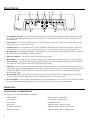
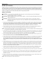
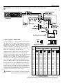
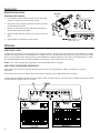
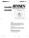
X150.1
INSTALLATION &
OPERATION
MONO AMPLIFIER
INTRODUCTION
Dear Customer,
Congratulations on your purchase of the world's finest brand of car audio amplifiers. At Rockford Fosgate we are fanatics
about musical reproduction at its best, and we are pleased you chose our product. Through years of engineering expertise,
hand craftsmanship and critical testing procedures, we have created a wide range of products that reproduce music with all
the clarity and richness you deserve.
For maximum performance we recommend you have your new Rockford Fosgate product installed by an Authorized Rockford
Fosgate Dealer, as we provide specialized training through Rockford Technical Training Institute (RTTI). Please read your warranty
and retain your receipt and original carton for possible future use.
Great product and competent installations are only a piece of the puzzle when it comes to your system. Make sure that your
installer is using 100% authentic installation accessories from Connecting Punch in your installation. Connecting Punch has
everything from RCA cables and speaker wire to Power line and battery connectors. Insist on it! After all, your new system
deserves nothing but the best.
To add the finishing touch to your new Rockford Fosgate image order your Rockford accessories, which include everything from
T-shirts and jackets to hats and sunglasses.
To get a free brochure on Rockford Fosgate products and Rockford accessories,
in the U.S. call 480-967-3565 or FAX 480-967-8132.
For all other countries, call +001-480-967-3565 or FAX +001-480-967-8132.
PRACTICE SAFE SOUND™
Continuous exposure to sound pressure levels over 100dB may cause permanent hearing loss. High
powered auto sound systems may produce sound pressure levels well over 130dB. Use common
sense and practice safe sound.
If, after reading your manual, you still have questions regarding this product, we recommend that you see your Rockford
Fosgate dealer. If you need further assistance, you can call us direct at 1-800-669-9899. Be sure to have your serial number,
model number and date of purchase available when you call.
The serial number can be found on the outside of the box. Please record it in the space provided below as your permanent
record. This will serve as verification of your factory warranty and may become useful in recovering your source unit if it is
ever stolen.
Serial Number: ______________________________
Model Number: _____________________________
TABLE OF CONTENTS
Introduction . . . . . . . . . . . . . . . . . . . . . . . . . . . . . . . 2
Safety Instructions . . . . . . . . . . . . . . . . . . . . . . . . . . . 3
Design Features . . . . . . . . . . . . . . . . . . . . . . . . . . . . . 4
Installation . . . . . . . . . . . . . . . . . . . . . . . . . . . . . . . 4-8
Installation Considerations . . . . . . . . . . . . . . . . . . . 4
Mounting Locations . . . . . . . . . . . . . . . . . . . . . . . . 5
Battery and Charging . . . . . . . . . . . . . . . . . . . . . . . 6
Wiring the System . . . . . . . . . . . . . . . . . . . . . . . . . 6
Using Passive Crossovers . . . . . . . . . . . . . . . . . . . . 7
Remote Punch Bass . . . . . . . . . . . . . . . . . . . . . . . . 8
NOTE: Review each section for more detailed information.
2
Operation . . . . . . . . . . . . . . . . . . . . . . . . . . . . . . . . . 8
Adjusting Gain . . . . . . . . . . . . . . . . . . . . . . . . . . . 8
Adjusting Crossover Frequency . . . . . . . . . . . . . . . 8
Troubleshooting. . . . . . . . . . . . . . . . . . . . . . . . . . . . . 9
Accessories . . . . . . . . . . . . . . . . . . . . . . . . . . . . . . . . 9
Specifications . . . . . . . . . . . . . . . . . . . . . . . . . . . . . 10
Limited Warranty Information . . . . . . . . . . . . . . . . . 11
GETTING STARTED
Welcome to Rockford Fosgate! This manual is designed to provide information for the owner, salesperson and installer. For
those of you who want quick information on how to install this product, please turn to the Installation Section of this manual. Other information can be located by using the Table of Contents. We, at Rockford Fosgate, have worked very hard to
make sure all the information in this manual is current. But, as we are constantly finding new ways to improve our product,
this information is subject to change without notice.
SAFETY INSTRUCTIONS
This symbol with “WARNING” is intended to alert the user to the presence of important instructions. Failure to heed the instructions will result in severe injury or death.
This symbol with “CAUTION” is intended to alert the user to the presence of important
instructions. Failure to heed the instructions can result in injury or unit damage.
! CAUTION: To prevent injury and damage to the unit, please read and follow the instructions in this manual.
We want you to have enjoyment from this system, not a headache.
! CAUTION: If you feel unsure about installing this system yourself, have it installed by a qualified Rockford
Fosgate technician.
! CAUTION: Before installation, disconnect the battery negative (-) terminal to prevent damage to the unit, fire
and/or possible injury.
CONTENTS OF CARTON
Model X150.1 Mono Amplifier
Remote Punch Bass Kit with Cord
Installation & Operation Manual
1 Fuse Connector
Mounting Hardware Kit
1 15 Amp Fuse
3
DESIGN FEATURES
1
2
3
8
4
5
6
9
7
10
1. Cast Aluminum Heatsink – The cast aluminum heatsink of the Punch amplifier dissipates heat generated by the amplifier's circuitry. The inherent advantage of casting provides a 30% improvement of cooling over conventional extrusion
heatsink designs.
2. Gain Control – The input gain control is preset to match the output of most source units. It can be adjusted to match
output levels from a variety of source units.
3. Variable Crossover – The amplifiers have a built-in 12dB/octave Butterworth filter with a crossover point variable from
50Hz to 250Hz. The crossover can be set to Low-Pass (LP) or it can be bypassed by setting it to Full Range (FULL).
4. RCA Input Jacks – The industry standard RCA jacks provide an easy connection for signal level input. They are gold-plated to resist the signal degradation caused by corrosion.
5. LED Power Indicator – The LED illuminates when the unit is turned on.
6. REM Terminal – This spade terminal is used to remotely turn-on and turn-off the amplifier when +12V DC is applied.
7. Power Terminals – The power and ground connectors on the Punch amplifier are gold-plated and will accommodate up
to 8 AWG wire maximizing the input current capability of the amplifier.
8. Punch Bass – The Punch Bass control helps correct for acoustical deficiencies in the listening environment by helping
produce full range sound without adding excessive boost.. The Punch Bass control is a narrow band adjustment at 45Hz
variable from 0dB to + 18dB. Connection is made with a cable using RJ-45 and can be installed under the dash for
remote control access.
9. RCA Pass-Thru Jacks – The Pass-Thru provides a convenient source for daisy-chaining an additional amplifier without
running an extra set of RCA cables from the front of the vehicle to the rear amplifier location.
10. Speaker Terminals – The heavy duty, gold-plated terminal block connectors (+ and –) will accept wire sizes from 8 AWG
to 18 AWG. These gold-plated connectors are immune to corrosion that can cause signal deterioration.
INSTALLATION
INSTALLATION CONSIDERATIONS
The following is a list of tools needed for installation:
4
Volt/Ohm Meter
Hand held drill w/assorted bits
Wire strippers
1/8" diameter heatshrink tubing
Wire crimpers
Assorted connectors
Wire cutters
Adequate Length—Red Power Wire
#2 Phillips screwdriver
Adequate Length—Remote Turn-on Wire
Battery post wrench
Adequate Length—Black Grounding Wire
INSTALLATION
This section focuses on some of the vehicle considerations for installing your new Amplifier. Pre-planning your system layout
and best wiring routes will save installation time. When deciding on the layout of your new system, be sure that each component will be easily accessible for making adjustments.
! CAUTION: If you feel unsure about installing this system yourself, have it installed by a qualified technician.
! CAUTION: Before installation, disconnect the battery negative (-) terminal to prevent damage to the unit, fire
and/or possible injury.
Before beginning any installation, follow these simple rules:
1. Be sure to carefully read and understand the instructions before attempting to install the Unit.
2. For safety, disconnect the negative lead from the battery prior to beginning the installation.
3. For easier assembly, we suggest you run all wires prior to mounting your Source Unit in place.
4. Route all of the RCA cables close together and away from any high current wires.
5. Use high quality connectors for a reliable installation and to minimize signal or power loss.
6. Think before you drill! Be careful not to cut or drill into gas tanks, fuel lines, brake or hydraulic lines, vacuum lines or
electrical wiring when working on any vehicle.
7. Never run wires underneath the vehicle. Running the wires inside the vehicle provides the best protection.
8. Avoid running wires over or through sharp edges. Use rubber or plastic grommets to protect any wires routed through
metal, especially the firewall.
9. ALWAYS protect the battery and electrical system from damage with proper fusing. Install the appropriate fuse holder and
fuse on the +12V power wire within 18” (45.7 cm) of the battery terminal.
10. When grounding to the chassis of the vehicle, scrape all paint from the metal to ensure a good, clean ground connection.
Grounding connections should be as short as possible and always be connected to metal that is welded to the main body,
or chassis, of the vehicle.
MOUNTING LOCATIONS
The mounting position of your amplified subwoofer will have a great effect on the sound performance produced.
Engine Compartment
Never mount this unit in the engine compartment. Mounting the unit in the engine compartment will void your warranty.
Trunk Mounting
Mounting the amplifier vertically will provide the best cooling of the amplifier.
Mounting the amplifier on the floor of the trunk will work but provides less cooling capability than vertical mounting.
Mounting the amplifier upside down to the rear deck of the trunk will not provide proper cooling and will severely affect the
performance of the amplifier and is strongly not recommended.
Passenger Compartment Mounting
Mounting the amplifier in the passenger compartment will work as long as you provide a sufficient amount of air for the
amplifier to cool itself. If you are going to mount the amplifier under the seat of the vehicle, you must have at least 1"
(2.54cm) of air gap around the amplifier's heatsink.
Mounting the amplifier with less than 1" (2.54cm) of air gap around the amplifier's heatsink in the passenger compartment
will not provide proper cooling and will severely affect the performance of the amplifier and is strongly not recommended.
5
INSTALLATION
BATTERY AND CHARGING
Amplifiers will put an increased load on the vehicle's battery and charging system. We recommend checking your alternator
and battery condition to ensure that the electrical system has enough capacity to handle the increased load of your stereo system. Stock electrical systems which are in good condition should be able to handle the extra load of any Rockford Fosgate
amplifier without problems, although battery and alternator life can be reduced slightly. To maximize the performance of your
amplifier, we suggest the use of a heavy duty battery and an energy storage capacitor.
WIRING THE SYSTEM
! CAUTION: If you do not feel comfortable with wiring your new unit, please see your local Authorized
Rockford Fosgate Dealer for installation.
! CAUTION: Before installation, disconnect the battery negative (-) terminal to prevent damage to the unit, fire
and/or possible injury.
! CAUTION: Avoid running power wires near the low level input cables, antenna, power leads, sensitive
equipment or harnesses. The power wires carry substantial current and could induce noise into
the audio system.
1. Plan the wire routing. Keep RCA cables close together but isolated from the amplifier's power cables and any high power
auto accessories, especially electric motors. This is done to prevent coupling the noise from radiated electrical fields into
the audio signal. When feeding the wires through the firewall or any metal barrier, protect them with plastic or rubber
grommets to prevent short circuits. Leave the wires long at this point to adjust for a precise fit at a later time.
2. Prepare the RED wire (power cable) for attachment to the amplifier by stripping 1/2" of insulation from the end of the
wire. Insert the bared wire into the B+ terminal and tighten the set screw to secure the cable in place.
NOTE: The B+ cable MUST be fused 18" or less from the vehicle's battery. Install the fuseholder under the hood and prepare
the cable ends as stated above. Connections should be water tight.
3. Trim the RED wire (power cable) within 18" of the battery and strip1/2"of insulation from the end of the wire. Cut the wire
loop that is attached to the fuseholder in half and splice the fuse into the power line using appropriate inline connectors.
Use the section of cable that was trimmed earlier and connect it to the other end of the fuseholder.
4. Strip 1/2" from the battery end of the power cable and crimp a large ring terminal to the cable. Use the ring terminal to
connect to the battery positive terminal. DO NOT install the fuse at this time.
5. Prepare the BLACK wire (Ground cable) for attachment to the amplifier by stripping 1/2" of insulation from the end of the
wire. Insert the bared wire into the GND terminal and tighten the set screw to secure the cable in place. Prepare the
chassis ground by scraping any paint from the metal surface and thoroughly clean the area of all dirt and grease. Strip the
other end of the wire and attach a ring connector. Fasten the cable to the chassis using a non-anodized screw and a star
washer.
6. Prepare the REM turn-on wire for connection to the amplifier by stripping 1/2" of insulation from the wire end. Insert the
bared wire into the REM terminal and tighten the set screw to secure the cable into place. Connect the other end of the
REM wire to a switched 12 volt positive source. The switched voltage is usually taken from the source unit's accessory
lead. If the source unit does not have this output available, the recommended solution is to wire a mechanical switch in
line with a 12 volt source to activate the amplifier.
7. Securely mount the amplifier to the vehicle or amp rack. Be careful not to mount the amplifier on cardboard or plastic
panels. Doing so may enable the screws to pull out from the panel due to road vibration or sudden vehicle stops.
8. Connect the source signal to the amplifier by plugging the RCA cables/high level inputs into the input jacks at the amplifier.
9. Connect the speakers. Strip the speaker wires 1/2" and insert into the speaker terminal and tighten the set screw to secure
into place. Be sure to maintain proper speaker polarity. DO NOT chassis ground any of the speaker leads as unstable
operation may result.
10. Perform a final check of the completed system wiring to ensure that all connections are accurate. Check all power and
ground connections for frayed wires and loose connections which could cause problems.
NOTE: Follow the diagrams for proper signal polarity.
6
INSTALLATION
! CAUTION: These amplifiers are not recommended for impedance loads below 2Ω.
USING PASSIVE CROSSOVERS
A passive crossover is a circuit that uses capacitors and/or
coils and is placed on speaker leads between the amplifier
and speaker. The crossover delegates a specific range of frequencies to the speaker for optimum driver performance. A
crossover network can perform one of three functions:
High-Pass (capacitors), Low-Pass (inductors or coils) and
Bandpass (combination of capacitor and coil).
The most commonly used passive crossover networks are
6dB/octave systems. These are easy to construct and
require one component per filter. Placing this filter in series
with the circuit will reduce power to the speaker by
6dB/octave above or below the crossover point depending
on whether it is a high-pass or low-pass filter. More complex systems such as 12dB/octave or 18dB/octave can
cause impedance problems if not professionally designed.
Passive crossovers are directly dependent upon the speaker's impedance and component value for accuracy. When
passive crossover components are used in multiple speaker
systems, the crossover's effect on the overall impedance
should be taken into consideration along with the speaker's
impedance when determining amplifier loads.
!
CAUTION: These amplifiers are not recommended for impedance loads below 2Ω.
L
C
6dB/Octave High-Pass
6dB/Octave Low-Pass
Speaker Impedance
Freq.
Hertz
2 OHMS
L
C
4 OHMS
8 OHMS
L
C
L
C
80
100
130
4.1mH 1000mF
3.1mH 800mF
2.4mH 600mF
8.2mH
6.2mH
4.7mH
500mF
400mF
300mF
16mH
12mH
10mH
250mF
200mF
150mF
200
260
400
1.6mH
1.2mH
.8mH
400mF
300mF
200mF
3.3mH
2.4mH
1.6mH
200mF
150mF
100mF
6.8mH
4.7mH
3.3mH
100mF
75mF
50mF
600
800
1000
.5mH
.41mH
.31mH
136mF
100mF
78mF
1.0mH
.82mH
.62mH
68mF
50mF
39mF
2.0mH
1.6mH
1.2mH
33mF
26mF
20mF
1200
1800
4000
.25mH
.16mH
.08mH
66mF
44mF
20mF
.51mH
.33mH
.16mH
33mF
22mF
10mF
1.0mH
.68mH
.33mH
16mF
10mF
5mF
6000
9000
12000
51mH
34mH
25mH
14mF
9.5mF
6.6mF
.10mH
68mH
51mH
6.8mF
4.7mF
3.3mF
.20mH
.15mH
100mH
3.3mF
2.2mF
1.6mF
L = Low-Pass (Inductor)
C = High-Pass (Capacitor)
For more information, see your Authorized Rockford Fosgate Dealer.
7
INSTALLATION
REMOTE PUNCH BASS
Mounting and installation
Mounting
Clip
1. Find a location, either under the dash or near the center
console, that gives easy access to the remote.
2. Using the screws supplied, install the mounting clip with
the tabs towards the back.
3. Route the cable for the remote and connect to both the
remote and amplified subwoofer.
4. Slip the remote onto the mounting clip until it snaps into
place.
Knob
Decal
5. Install the decal and knob onto the remote.
OPERATION
ADJUSTING GAIN
To adjust the gain setting, turn the amplifier gains all the way down. Turn the source unit volume up until distortion is audible
and then turn it down a bit until the distortion is inaudible. This will be about two thirds all the way up on most source units.
Next, turn the amplifier gain setting until once again distortion is audible and then back it down until the distortion is inaudible. Rockford Fosgate source units do not distort, so the volume can be used at maximum setting.
NOTE: For a more in depth setting procedure, contact Rockford Technical Support.
ADJUSTING CROSSOVER FREQUENCY
Placing the switch in the Full position sets the amplifier to the full range frequency mode, preventing any crossover
adjustment.
Placing the switch in the LP position allows the crossover frequency to be adjusted between 50-250Hz.
Turn the crossover adjustment knob all the way down. With the system playing, turn the crossover adjustment knob up slowly
until the desired crossover point is achieved.
8
TROUBLESHOOTING
NOTE: If you are having problems after installation follow the Troubleshooting procedures below.
Procedure 1: Check Amplifier for proper connections.
Verify that POWER light is on. If POWER light is on skip to Step 2, if not continue.
1. Check in-line fuse on battery positive cable. Replace if necessary.
2. Verify that Ground connection is connected to clean metal of the vehicle’s chassis. Repair/replace if necessary.
3. Verify there is 10.5 - 15.5 Volts of current present at the positive battery and remote turn-on cable. Verify quality connections for both cables at amplifier, stereo, and battery/fuseholder. Repair/replace if necessary.
Procedure 2: Check Amplifier for audio output.
1. Verify good RCA/high-level input connections at stereo and amplifier. Check entire length of cables for kinks, splices, etc.
Test RCA/high-level inputs for AC current with stereo on. Repair/replace if necessary.
2. Disconnect RCA/high-level input from amplifier. Connect RCA/high-level input from test stereo directly to amplifier input.
Procedure 3: Check Amplifier if you experience Turn-on Pop.
1. Disconnect input signal to amplifier and turn amplifier on and off.
2. If the noise is eliminated, connect the REM lead of amplifier to source unit with a delay turn-on module.
OR
1. Use a different 12 Volt source for REM lead of amplifier (i.e. battery direct).
2. If the noise is eliminated, use a relay to isolate the amplifier from noisy turn-on output.
Procedure 4: Check Amplifier if you experience excess Engine Noise.
1. Route all signal carrying wires (RCA, Speaker cables) away from power and ground wires.
OR
2. Bypass any and all electrical components between the stereo and the amplifier(s). Connect stereo directly to input of
amplifier. If noise goes away the unit being bypassed is the cause of the noise.
OR
3. Remove existing ground wires for all electrical components. Reground wires to different locations. Verify that grounding
location is clean, shiny metal free of paint, rust etc.
OR
4. Add secondary ground cable from negative battery terminal to the chassis metal or engine block of vehicle.
OR
5. Have alternator and battery load tested by your mechanic. Verify good working order of vehicle electrical system including distributor, spark plugs, spark plug wires, voltage regulator etc.
ACCESSORIES
Connecting PUNCH Capacitors
Maintain the power you need to your Punch Amplifier.
Connecting Links
Mount your Punch Amplifiers together for space reduction and a smooth look.
See our website for other accessories to help you get the most out of your system.
www.rockfordfosgate.com
9
SPECIFICATIONS
MODEL
PUNCH X150.1
Peak Power Rating - Measured at 14.4 Volts
Mono into a 2Ω Load
400 Watts
Dynamic Power Rating (IHF-202 Standard) - Measured at 14.4 Volts
Mono into a 4Ω Load
110 Watts
Mono into a 2Ω Load
190 Watts
Continuous Power Rating (Competition Standard) - Measured at 13.8 Battery Volts
RMS continuous power mono, driven into a
4Ω load from 20 to 20,000Hz with less than
0.05% Total Harmonic Distortion (THD)
75 Watts
RMS continuous power mono, driven into a
2Ω load from 20 to 20,000Hz, with less than
0.1% Total Harmonic Distortion (THD)
150 Watts
Signal-to-Noise Ratio
Crossover Slope
Crossover Frequency
Dimensions
>100dB A-weighted
24dB/octave Butterworth
variable from 50Hz to 250Hz
2.60" (6.60cm) H
9.60" (24.38cm) W
6.70" (17.01cm) L
Frequency Response
20Hz to 20kHz ±0.5dB
Bandwidth
10Hz to 200kHz ±3dB
Damping Factor @ 4Ω (at output connector )
Slew Rate
IM Distortion (IHF)
Source Unit Compatibility (+15dB gain overlap)
Input Sensitivity (+0dB gain overlap)
>200
30 Volts/ms
<0.05%
17V max. (low level in)
Variable from 250mV to 4V (low level in)
Variable from 650mV to 11V (high level in)
Protection
Battery Fusing Rates (External to Amplifier)
Fuse Type
Equalization (45Hz Punch Bass)
Input Impedance
Specifications subject to change without notice
10
NOMAD - Internal analog-computer output protection
circuitry limits power in case of overload. Thermal
switch shuts down the amplifier in case of overheating.
15 amps
ATC
Variable from 0dB to +18dB @ 45Hz
20k ohms
LIMITED WARRANTY INFORMATION
Rockford Corporation offers a limited warranty on Rockford Fosgate products on the following terms:
Length of Warranty
3 years on electronics
1 year on source units
1 year on speakers
90 days on electronic B-stock (receipt required)
90 days on speaker B-stock (receipt required)
What is Covered
This warranty applies only to Rockford Fosgate products sold to consumers by Authorized Rockford Fosgate Dealers in the
United States of America or its possessions. Product purchased by consumers from an Authorized Rockford Fosgate Dealer
in another country are covered only by that country’s Distributor and not by Rockford Corporation.
Who is Covered
This warranty covers only the original purchaser of Rockford product purchased from an Authorized Rockford Fosgate
Dealer in the United States. In order to receive service, the purchaser must provide Rockford with a copy of the receipt
stating the customer name, dealer name, product purchased and date of purchase.
Products found to be defective during the warranty period will be repaired or replaced (with a product deemed to be
equivalent) at Rockford's discretion.
What is Not Covered
1. Damage caused by accident, abuse, improper operations, water, theft
2. Any cost or expense related to the removal or reinstallation of product
3. Service performed by anyone other than Rockford or an Authorized Rockford Fosgate Service Center
4. Any product which has had the serial number defaced, altered, or removed
5. Subsequent damage to other components
6. Any product purchased outside the U.S.
7. Any product not purchased from an Authorized Rockford Fosgate Dealer
Limit on Implied Warranties
Any implied warranties including warranties of fitness for use and merchantability are limited in duration to the period of
the express warranty set forth above. Some states do not allow limitations on the length of an implied warranty, so this limitation may not apply. No person is authorized to assume for Rockford Fosgate any other liability in connection with the
sale of the product.
How to Obtain Service
Please call 1-800-669-9899 for Rockford Customer Service. You must obtain an RA# (Return Authorization number) to
return any product to Rockford Fosgate. You are responsible for shipment of product to Rockford.
Ship to: Electronics
Rockford Corporation
Warranty Repair Department
2055 E. 5th Street
Tempe, AZ 85281
RA#: _________________________
Ship to: Speakers
Rockford Acoustic Design
Speaker Returns
2356 Turner Ave. NW
Grand Rapids, MI 49544
RA#: ____________________
11
Rockford Fosgate
Rockford Corporation
546 South Rockford Drive
Tempe, Arizona 85281 U.S.A.
In U.S.A., (480) 967-3565
www.rockfordfosgate.com
09/01 B.M.
MAN-3774-A
Printed in U.S.A