1
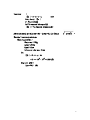
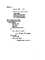
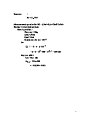
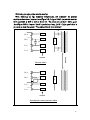
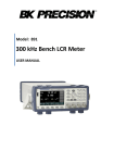
MPT LCR01A/B
Handheld LCR bridge meter
User manual
Featured:
1. Adapt DSP technology to achieve fast measuring speed, high accuracy and high
reliability.Measuring frequency can be set at 100K/10K/1K/120/100/20 Hz (LCR01A)
or 1M/500K/100K/10K/1K/100Hz(LCR01B)。
2. Measuring parameter:Main parameter Z,Lp,Ls,Cp,Cs,DCR and subparameter
ESR,D,Q,θ can be displayed in any combination.
Contents
1.
1.1.
1.2.
1.3.
1.4.
2.
2.1.
2.2.
2.3.
2.4.
2.5.
2.6.
2.7.
2.8.
2.9.
2.10.
2.11.
3.
MPT LCR01A/B Introduction
Function introduction
Impedance definition
Accuracy and specification
Accessory
Manual illustration
Panel
Power
Open/Short calibration
Display speed
Relative mode
Manual range operation
DC impedance measurement
AC impedance measurement
Capacitance measurement
Inductance measurement
Accessory operated illustration
Usage illustration
Maintain illustration
Notice
Cable connection technique
3.1.
3.2.
Appendix
1
Appendix Open/Short circuit compensation
2
Appendix Serial/Parallel mode selection
3
Page
2
2
3
5
13
14
14
15
17
18
18
18
18
19
19
20
21
24
24
24
25
33
35
1
1.
MPT LCR01A/B Introduction
1.1. Function introduction:
MPT LCR01A/B is an innovative AC/DC impedance meter,also include
capacitance and inductance measurement。It differ from traditional meter,MPT
LCR01A/B adapts DSP(Digital Signal Process) technique,Technicians and
engineers will get various conveniences from this advanced meter。
Features of MPT LCR01A/B:
●Frequency:100K/10K/1K/120/100/20 Hz(LCR01A)
:1M/500K/100K/10K/1K/100Hz(LCR01B)
●Level:1Vrms/0.25Vrms/0.05Vrms/1.25Vdc(LCR01A)
:0.6Vrms/0.25Vrms/0.05Vrms/0.6Vdc(LCR01B)
● Measuring Parameter:Z,Lp,Ls,Cp,Cs,DCR,
ESR,D,Q,θ
● Basic accuracy:0.2%(=<10KHz),0.4%(100KHz)
,1%(500KHz),2%(1MHz)
● Dual LCD display
● DSP fast measuring
● Auto range/Range hold
● Open/Short compensation
● Display parameters:
:Impedance
Z
DCR :DC Resistance
:Inductance parallel
Lp
:Inductance series
Ls
:Capacitance parallel
Cp
:Capacitance series
Cs
θ
:Impedance phase angle
: Effective Series Resistance
ESR
:Dissipation factor
D
:Quality factor
Q
● Display assembly:
Serial mode: Z-θ
, Z-ESR
Cs-D
, Cs-Q
, Z-D
, Cs-θ
, Z-Q
, Cs-ESR
2
Ls-D
, Ls-Q
, Ls-θ
Parallel mode: Cp-D
Lp-D
, Cp-Q
, Lp-Q
, Cp-θ
, Lp-θ
, Ls-ESR
1.2. Impedance parameter definition
According to the different measuring signal of impedance meter,It can be separated
DC and AC impedance meter。The popular multimeter in market is a DC resistance
meter;The MPT LCR01A/B is an AC/DC impedance meter。For electronic Circuit,
component and material,impedance is an important parameter。
In engineering,vector is used to express impedance,It analysed real part Resistance(R)
and imagine part reactance(X) ; And the polar express impedance(Magnitude) and
Theta(Phase)。Diagrams below show the relation。
3
Imaginary Axis
Xs
Z(Rs , Xs)
∣Z∣
θ
Real Axis
Rs
圖 一
Z = Rs+jXs =∣Z∣∠θ(Ω)
Rs =∣Z∣Cosθ
∣Z∣=
Xs =∣Z∣Sinθ
θ
Rs 2 + Xs 2
= Tan -1 (Xs/Rs)
Z:Impedance
Rs:Resistance
Xs:Reactance
Ω:Unit Ohm
4
Reactance can be separated as(Inductive) XL and(Capacitive) XC。The definition as:
XL =ωL=2πfL
and
XC =(ωC) -1 =(2πfC) -1
L:Inductance (H)
C:Capacitance (F)
f:Frequency (Hz)
Additional,other parameters are attached to passive component,Quality factor(Q) and
Dissipation Factor(D)。Both are defined the purity of reactance,that is the energy
storage(reactance) and the energy consumption(resistance)ratio,defined as follow:
Q=D -1 = (tanδ) -1
=∣Xs∣.Rs-1=ω.Ls.Rs-1=(ω.Cs.Rs) -1
=∣B∣.G-1
= Rp.∣Xs∣-1=Rp.(ω.Lp) -1=ω.Cp.Rp
Quality factor is applied on inductive components,and Dissipation factor is applied
on capacitive components。Both are reciprocal each other。
Traditional,component can be analysed as series equivalent and parallel equivalent。
Both defined as follow。
Series connection
parallel connection
1.3. Specification and Accuracy
5
●LCD display:
parameter Range
Z
0.000Ω ~ 9999MΩ
L
0.000μH ~ 9999H(LCR01A)
0.0xxnH ~ 9999H(LCR01B)
C
0.000pF ~ 9999F
DCR
0.000Ω ~ 9999MΩ
ESR
0.000Ω ~ 9999Ω
D
0.000 ~ 9999
Q
0.000 ~ 9999
Θ
﹣180.0° ~ 180.0°
●Accuracy(Ae)
:
750K
∫
100K
(Ω)
100K
∫
20K
(Ω)
20K
∫
10
(Ω)
2% ± 1% ± 0.5%
±1
1
20Hz(LCR01A)/100Hz 1*
0.2%
±1
0.2%
±1
5% ± 2% ± 0.4%
1*
1
±1
0.4%
±1
Ae
Freq.
∣Zx∣ 20M
∫
10M
(Ω)
10M
∫
750K
(Ω)
DCR
10
∫
1
(Ω)
1
∫
0.1
(Ω)
0.5% ± 1 1% ± 1
*
*
2%±1*
5% ± 1
120Hz(LCR01A)
1KHz
10KHz
5% ± 2% ±
1*
1
100KHz
UnD
500KHz
(LCR01B)
UnD
1MHz
(LCR01B)
UnD
UnD
UnD
10%
±1
5% ± 1% ± 5%±1*
1
1
UnD
10%
±1
*
10% ± 1
*
2% ± 10% ± 1 20%
*
1
±1*
Accuracy show above is true when 1Vrms measuring level used。
Ae X 1.25 if 250mVrms measuring level used 。
Ae X 1.50 if 50mVrms measuring level used 。
6
measuring L and C,if Dx>0.1, then Ae X
(1+Dx2)。
Measuring ESR,if Qx>0.1, then Ae X
(1+Qx2) 。
* Measuring level set to 50mV, Ae undefined。
Z accuracy
C accuracy
:shown on table 1.
:
∣Zx∣=(2.π.f.Cx) -1
(Ω)
CAe=Ae of ∣Zx∣
f:frequency(Hz)
Cx:The measured capacitance(F)
∣Zx∣:The measured impedance(Ω)
Above accuracy is true when Dx<0.1,if D x>0.1then CAe X
(1+Dx2)。
Example:C accuracy calculate
Measuring condition:
Frequency:1KHz
Level:1Vrms
Speed:Slow
Capacitance under test:100nF
Then
∣Zx∣=(2.π.f.Cx) -1
∣Zx∣=(2.π.103.100.10-9) -1=1590 (Ω)
look up on table 1:
CAe=±0.2 (%)
7
L accuracy
:
∣Zx∣=2.π.f.L
(Ω)
LAe=Ae of ∣Zx∣
f:Frequency(Hz)
Lx:The measured inductance(H)
∣Zx∣:The measured impedance(Ω)
Above accuracy is true when Dx<0.1,if D x>0.1 then CAe X
(1+Dx2)
。
Example:L accuracy calculation
Measuring condition:
Frequency:1KHz
Level:1Vrms
Speed:Slow
Inductance under test:1mH
then
∣Zx∣=2.π.f.Lx
∣Zx∣=2.π.103.10-3=6.283 (Ω)
look up on table 1:
LAe=±0.5 (%)
8
ESR accuracy
:
±Xx.Ae. 100-1
(Ω)
Xx=2.π.f.Lx=(2.π.f.Cx) -1
f:Frequency(Hz)
Xx:The measured impedance(Ω)
Lx:The measured inductance(H)
Cx:The measured capacitance(F)
Above accuracy is true when Dx<0.1。
Example:Cs-ESR accuracy calculation
Measuring condition:
Frequency:1KHz
Level:1Vrms
Speed:Slow
Capacitance under test:100nF
then
∣Zx∣=Xx=(2.π.f.Cx) -1
∣Zx∣=(2.π.103.100.10-9) -1=1590 (Ω)
look up on table 1:
CAe=±0.2 (%)
ESR A e=±Xx.Ae/100
= ±1590 X 0. 2 / 100 = ± 3.18
(Ω)
9
D accuracy
:
De=±A e /100
Above accuracy is true when Dx<0.1,if D x>0.then CAe X (1+Dx)。
Example:C-D accuracy calculation
Measuring condition:
Frequency:1KHz
Level:1Vrms
Speed:Slow
Capacitance under test:100nF
then
∣Zx∣= (2.π.f.Cx) -1
∣Zx∣=(2.π.103.100.10-9) -1=1590 (Ω)
look up on table 1:
CAe=±0.2 (%)
D A e= ±CAe /100
= ±0.2/100= ±0.002
10
Q accuracy
:
Qe=±(Qx2.De)/(1 Qx.De)
Qx:The measured Q value。
De:relative D accuracy。
Above accuracy is true when Qx.De<1。
Example:C-Q accuracy calculation
Measuring condition:
Frequency:1KHz
Level:1Vrms
Speed:Slow
Inductance under test:1mH
then
∣Zx∣=2.π.f.Lx
∣Zx∣=2.π.103.10 -3=6. 283 (Ω)
look up on table 1:
LAe=±0.5 (%)
De=±Ae/100=±0.005
If the measured Qx=20
QAe=±(Qx2.De/(1 Qx.De) )=± ( 2/(1 0.1) )
11
Θ accuracy
:
θe= (180/π)/(Ae/100) (Deg)
Example:Z-θaccuracy calculation
Measuring condition:
Frequency:1KHz
Level:1Vrms
Speed:Slow
Capacitance under test:100nF
then
∣Zx∣=(2.π.f.Cx) -1
∣Zx∣=1/(2.π.103.100.10 -9)=1590 (Ω)
look up on table 1:
ZAe=±0.2 (%)
θAe=±(180/π)/(ZAe/100)=±0.115
(Deg)
12
●measuring signal:
Level accuracy:10%
Frequency accuracy:0.01%
●Output impedance:100Ω±5%
●Measuring speed:depend on frequency
Fast:5times/second(10KHz)
Slow:2.5times/second(10KHz)
●Power low notify:
Input or battery power lower than 6.2Volt
●Battery:
Charge current:about 18mA
Battery type:Ni-Mh
Life:3.0 hr(LCR01A) ,1.5 hr(LCR01B)
●Adapter:
Input:110V/220Vac 50/60Hz
Output:12Vdc
●Operation environment:
Temperature:0℃ to 40℃ (operation)
-20℃ to 70℃ (storage)
Humidity:≦85% R.H. at 40℃
Size:178mm × 86 mm × 45mm
7"× 3.4"× 1.8" (L×W×H)
Weight:300g
13
1.4. Accessory
●LCR01A/B Operation manual
●LCR01A or LCR01B one set
●Ni-Mh rechargeable battery
●Shorted Bar
●5 wire/0.75mSMD test probe
●5 wire/0.75m Kelvin Clips test cable
●AC power adaptor
14
2.
1.
2.
3.
4.
5.
6.
7.
8.
9.
10.
User operate illustration
2.1. Panel:
Main parameter display LCD
Low voltage indicator
Machine type
Level switch button
Frequency switch button
Display speed switch Button
Z/DCR/C/L display switch button
Hpot/Hcur terminal
Lpot/Lcur terminal
Battery house
11.
12.
13.
14.
15.
16.
17.
18.
Subparameter display LCD
Power ON/OFF switch
Open/Short calibration button
Relative mode button
Θ/D/Q/ESR display switch button
Auto/Range hold switch button
Guard terminal
Power adaptor input hole
15
2.2. Power:
●Battery supply
Remove battery cup,clean battery house,put the pull-up tape under battery
and put battery into the battery house in proper direction,then put on the battery
cup 。 If the battery is not chargeable , remove the power adaptor input
connector;If the battery is chargeable,power adaptor input connector can be
plug-in。
16
●Power adaptor supply
If battery not available,It can be powered by power adaptor。If the power
adaptor is plug-in and the power switch on LCR01A/B is off,It will charge
battery on battery house。
17
2.3. Open/Short calibration:
LCR01A/B function with Open/Short calibration to meet the measuring of
High/Low impedance measurement。
●Open calibration
Clean the measuring terminal,make it on open state,press【CAL】button
about 1 second,main parameter will display「CALO」and a “bi" sound will
be heard,Calibration time will depend on measuring frequency,the high
frequency,the lower calibration time needed;After calibration, a “bi" sound
will be heard again。
●Short calibration
Plug-in shorted bar first,press【CAL】about 2 seconds,till「CALS」shown
on main display,and a “bi" sound will be heard;After calibration, a “bi"
sound will be heard again。
18
2.4. ●Display refresh:
LCR01A/B functions with Fast/Slow display refresh mode,User press the
【Speed】button will toggle speed mode。on『Fast』mode,the refresh
speed will be twice of『Slow』mode,the more of the measuring frequency,
the faster of the refresh speed。
2.5. ●Relative mode
LCR01A/B functions with measuring relative mode,user put a reference
component on the test terminals。Then press 【Relative】button。And remove
this reference component from the test terminals,put other device under test on
test terminals then,the main LCD display will display the result of subtraction
of the reference value from the measuring one。
2.6. ●Range hold mode
LCR01A/B functions with autorange/range_hold mode,put a reference component on
the test terminals,then wait until display stable,press【Range Hold】button。
『RH』
will be shown on sub-parameter display LCD,LCR01A will set this measuring
range。Remove this reference component and put other component under test on test
terminals,the measured result will gotten faster。But care should be taken,the
measured range should in the range 2 and 1/2 of the reference value。
2.7. ●DC impedance measuring
Press【L/C/Z/DCR】
,till
『DCR』
shown on main parameter display LCD,then LCR01A/B
will be in the DC impedance measuring mode。
19
2.8. ●AC impedance measuring
Press【L/C/Z/DCR】
,till『Z』shown on main parameter display LCD,then LCR01A/B
will be in the AC impedance measuring mode。
2.9. ●Capacitance measuring
Depend on component equivalent,Capacitance measuring can be separated as(Cs,Serial
Mode) and (Cp,Parallel Mode),user can press【L/C/Z/DCR】button as they need。If
『Cs』mode selected,then press button【θ/D/Q/ESR】select one of the fourθ/D/Q/ESR
sub-parameter。If『Cp』mode selected,then press button【θ/D/Q/ESR】select one of
the threeθ/D/Q sub-parameter。
20
2.10. ●Inductance measuring
Inductance measuring can be separated as(Ls,Serial Mode) and (Lp,Parallel Mode),user
can press【L/C/Z/DCR】button as they need。If『Ls』mode selected,then press button
【θ/D/Q/ESR】select one of the fourθ/D/Q/ESR sub-parameter。If『Lp』mode selected,
then press button【θ/D/Q/ESR】select one of the threeθ/D/Q sub-parameter。。
21
22
2.11. ●Accessory operation
To insure measuring accuracy and stable,perform「LOCK」action when test probe been
used。
Shorted Bar
23
SMD Test Probe
24
Kelvin Clip Test Probe
25
3.
Use noted
3.1. Service information
MPT warrants to the original purchaser that its products and the component
thereof ,will be free from defects in workmanship and materials for a period of
one year from date of purchase。
3.2. Items notes
●Don't open the device case beside battery cap。
●Keep measuring terminals clean to insure measuring accuracy。
●During measuring,keep hands away form device above 10cm。
●Discharge capacitor before measuring。
●When low voltage alarm,then replace battery or charge with adaptor。
●Remove battery if long period don't use。
26
Appendix Cable connection technique
一
Auto-balancing Bridge has four terminals(Hcur、Hpot、Lcur、and
Lpot)to connect the device under test(DUT).It is important to understand
what connection method will affect the measurement accuracy。
Two terminal(2T)is the simplest way to connect the DUT,but it
contents many errors which are the inductor and resistor as well as the
parasitic capacitor of the test leads(figure 1)。Due to these errors in
measurement,The effective impedance measurement range will be limit
at 100Ωto 10KΩ。
27
Ro
HCUR
A
●
●
Lo
●
HPOT
D
U
T
V
Co
D
U
T
LPOT
●
●
LCUR
●
Ro
Lo
2T
Impe Ω
1m
10m 100m
1
10
100
1K
10K
100K
1M
10M
Figure 1.
28
3-Terminals(3T) uses coaxial cable to reduce the effect of the
parasitic capacitor,the shield of the coaxial cable should be connect
to Guard of the instrument to increase the measurement range up to
10 MΩ。
Ro
HCUR
●
●
Lo
A
●
HPOT
D
U
T
V
Co
D
U
T
LPOT
●
●
LCUR
●
●
Ro
Lo
Co no effect on test result
Figure 2.
29
●
A
D
U
T
V
●
●
2-T with shielding
3T
impe Ω
1m
10m 100m
1
10
100
1K
10K
100K
1M
10M
Figure 2 (continued)
30
4-Terminal(4T)connection reduces the effect of the test lead
resistance,this connection can improve the measurement range
down to 10mΩ。However,the inductance of the test lead can not be
eliminated。
HCUR
A
HPOT
●
D
U
T
V
D
U
T
LPOT
●
LCUR
4T
Impe Ω
1m
10m 100m
1
10
100
1K
10K
100K
1M
10M
Figure 3.
31
5-Terminal connection is the combination of 3T and 4T。It has
four coaxial cable。Due to the advantage of 3T and 4T,this
connection can widely increase the measurement range for 10mΩ
to 10MΩ。
HCUR
A
●
HPOT
●
D
U
T
D
U
T
V
LPOT
●
LCUR
5T
Impe Ω
1m
10m 100m
1
10
100
1K
10K
100K
1M
10M
32
●
A
●
V
D
U
T
●
Wrong connection of 4T
Figure 4.
4-terminal path(4TP) connection solves the problem that caused
by the test lead inductance。4TP uses four coaxial cables to isolate
the current path and the voltage sense cable。The return current will
flow through the coaxial cable as well as the shield
。Therefore,the magnetic flux that generated by internal conductor
will cancel out the magnetic flux generated by external
conductor(shield)。The 4TP increase the measurement range from
1mΩ to 10MΩ。
33
HCUR
A
●
HPOT
●
D
U
T
D
U
T
V
LPOT
●
LCUR
5T
Impe Ω
1m
10m 100m
1
10
100
1K
10K
100K
1M
10M
34
HCUR
●
HPOT
V
D
U
T
D
U
T
●
LPOT
LCUR
A
4T
Impe Ω
1m
10m 100m
1
10
100
1K
10K
100K
1M
10M
35
Eliminating the effect of the parasitic capacitor
When measuring the high impedance component(i.e. low capacitor),the parasitic
capacitance becomes an important issue(Figure 3.6)。In figure 3.6(a),the parasitic capacitor
Cd is paralleled to DUT as well as Ci and Ch,To correct this problem。Add a guard
plane(Figure 3.6b) in between H and L terminals to break the Cd。If the guard plane is
connected to instrument guard,The effect of Ci and Ch is removed。
Ch
HCUR
HPOT
Cd
D
U
T
LPOT
LCUR
Cl
Ground
contact
Parastic effect
HCUR
HPOT
Guard plant
D
U
T
LPOT
LCUR
contact
Guard plant reduces parastic effect
36
Append
Open/Short compensation
2
For those precision impedance measuring instrument,the open and short
compensation need to be used to reduce the parasitic effect of the test
fixture。The parasitic effect of the test fixture can be treated like the simple
passive components in figure 3.7a。When the DUT is open,the instrument gets
the conductance Yp=Gp+jwCp(Figure 3.7b) 。When the DUT is short,the
instrument gets the impedance Zs=Rs+jwLs(Figure 3.7c)。After open and
short compensation,Yp and Zs are for calculating the real Zdut(Figure 3.7d)。
Parastic of test fixture
Redundant Zs
HCUR
Rs
●
Parastic Yo
Ls
●
●
HPOT
Zm
Co
Go
D
U
T
LPOT
●
●
●
LCUR
Parastic effect of test fixture
37
HCUR
Rs
Ls
●
●
●
HPOT
Yo
Co
Go
OPEN
LPOT
●
●
●
LCUR
Yo=Go+jωCo
Rs+jω«(Go+jωCo)-1
Open ckt
HCUR
Rs
●
Ls
●
HPOT
●
●
Zs
Co
Go
SHORT
LPOT
●
●
●
LCUR
Zs=Rs+jωLs
Short ckt
Zs
●
Yo
Zm
Zdut
Zdut =
Zm-Zs
1-(Zm-Zs)Yo
●
38
Appendi Selecting the series or parallel mode
x3
According to different measuring requirement,there are series and parallel modes
to describe the measurement result。It is depending on the high or low impedance
value to decide what mode to be used。
●capacitor
The impedance and capacitance in the capacitor are negatively proportional。
Therefore,the large capacitor means the low impedance;the small capacitor means
the high impedance。Figure below shows the equivalent circuit of capacitor。If the
capacitor is small,the Rp is more important than the Rs。If the capacitor is large,
the Rs shouldn't be avoided。Hence,uses parallel mode to measure low capacitor
and series mode to measure high capacitor。
Small
C
C
Large C
Rp effect
Rs no effect
C
Rp no effect
Rs effect
39
●Inductor
The impedance and inductive in the inductor are positively proportional。Therefore,the
large inductor equals to the high impedance and vice versa。Figure below shows the
equivalent circuit of inductor。If the inductor is small,the Rs is more important than Rp,
If the inductor is large,The Rp should be taking care of。So,uses series mode to measure
low inductor and parallel mode to measure high inductor。
Small
Large L
L
Rp effect
L
L
Rp no effect
Rs no effect
Rs effect
According to analysis above:
1. Impedance below 10Ω,series mode selected。
2. Impedance above 10KΩ,parallel mode selected。
3. Between 10Ω and 10KΩ depend on needed。
Example:
DUT=100pF
Freq.=10KHz
Z=159.2KΩ
parallel mode selected。
Example:
DUT=100μΗ
Freq.=10KHz
Z=6.2832Ω
Serial mode selected。
C. Accuracy:
40
20Hz
100Hz
120Hz
1KHz
10KHz
795.5 μF
795.5 μF
∫
7.955 mF
7.955 mF
∫
79.55 mF
0.5%±1
0.2%±1
0.5%±1
1%±1
159.1 pF
∫
2.121 nF
1.212 nF
∫
15.91 nF
15.91 nF
∫
159.1 μF
∫
159.1 μF
1591 μF
1591 μF
∫
15.91mF
2%±1
1%±1
0.5%±1
0.2%±1
0.5%±1
1%±1
66.31pF
∫
132.6pF
132.6pF
∫
1.768nF
1.768nF
∫
13. 26nF
13.26nF
∫
132. 6μF
∫
132. 6μF
1326μF
1326μF
∫
13.26mF
2%±1
1%±1
0.5%±1
0.2%±1
0.5%±1
1%±1
7. 957 pF
∫
15.91 pF
15.91 pF
∫
212.1 pF
212.1 pF
∫
1.591 nF
1.591 nF
∫
15.91 μF
∫
15.91 μF
159.1 μF
159.1 μF
∫
1.591 mF
2%±1
1%±1
0.5%±1
0.2%±1
0.5%±1
1%±1
0. 795 pF
∫
1.591 pF
1.591 pF
∫
21.21 pF
21.21 pF
∫
159.1 pF
159.1 pF
∫
1.591 μF
∫
15.91 μF
∫
1.591 μF
15.91 μF
159.1 μF
5%±1
2%±1
0.5%±1
0.2%±1
0.5%±1
1%±1
0.159 pF
∫
2.121 pF
2.121 pF
∫
15.91 pF
15.91 pF
∫
159.1 nF
159.1 nF
∫
1.591 μF
∫
1.591 μF
15.91 μF
5%±1
2%±1
0.4%±1
2%±1
5%±1
0.159 pF
∫
2.121 pF
2.121 pF
∫
15.91 pF
15.91 pF
∫
31.91 nF
31.91 nF
∫
319.1 nF
319.1 n F
∫
10%±1
5%±1
1%±1
5%±1
10%±1
0.079 pF
∫
1.111 pF
1.111 pF
∫
7.999 pF
7.999 pF
∫
15.91 nF
15.91 nF
∫
159.1 nF
159.1 nF
∫
1.591 μF
20%
10%±1
2%±1
10%±1
20%±1
398 pF
∫
795.5 pF
795.5 pF
∫
10.6 nF
10.6 nF
∫
79.55 nF
2%±1
1%±1
79.57 pF
∫
159.1 pF
100KHz NA
NA
500KHz NA
NA
1MHz NA
NA
79.55 nF
∫
3.191 μF
41
L Accuracy:
20Hz
100Hz
120Hz
1KHz
10KHz
100KHz
159.3 KH
∫
79.55 KH
79.55 KH
∫
5965 H
5965 H
∫
795.5 H
795.5 H
∫
79.55 mH
79.55 mH
∫
7.955 mH
7.955 mH
∫
2%±1
1%±1
0.5%±1
0.2%±1
0.5%±1
1%±1
31.83 KH
∫
15.91 KH
15.91 KH
∫
1193H
1193H
∫
159. 1 H
159. 1 H
∫
15. 91 mH
15. 91 mH
∫
1.5 91 mH
1.591 mH
∫
2%±1
1%±1
0.5%±1
0.2%±1
0.5%±1
1%±1
26.52KH
∫
13. 26KH
13. 26KH
∫
995H
995H
∫
132. 6H
132. 6H
∫
13. 26mH
13. 26mH
∫
1.326mH
1.326mH
∫
132. 6μH
2%±1
1%±1
0.5%±1
0.2%±1
0.5%±1
1%±1
31. 83 KH
∫
1. 591 KH
1. 591 KH
∫
119.3 H
119.3 H
∫
15. 91 H
15. 91 H
∫
1. 591 mH
1. 591 mH
∫
159.1 μH
∫
159.1 μH
15. 91 μH
2%±1
1%±1
0.5%±1
0.2%±1
0.5%±1
1%±1
11.93H
∫
1. 591 H
1. 591 H
∫
159. 1 μH
∫
15.91 μH
∫
159. 1 μH
15.91 μH
1. 591 μH
318.3H
∫
159. 1 H
159. 1 H
∫
11.93H
79.55 μH
159. 1μH
5%±1
2%±1
0.5%±1
0.2%±1
0.5%±1
1%±1
31. 83 H
∫
15. 91 H
15. 91 H
∫
1.193 H
1. 193H
∫
159. 1 mH
159. 1 mH
∫
15.91 μH
∫
1.591 μH
∫
15. 91 μH
1. 591 μH
0. 159 μH
5%±1
2%±1
0.4%±1
2%±1
5%±1
32.26 mH
∫
6.363 mH
6.363 mH
∫
3.181 μH
∫
3.181 μH
0.318 μH
0.031 μH
1%±1
5%±1
10%±1
3.181 mH
∫
1.591 μH
∫
0.159 μH
∫
1.591 μH
0.159 μH
0. 015 μH
2%±1
10%±1
20%±1
NA
500KHz NA
NA
NA
NA
5%±1
1MHz NA
NA
16.13 mH
∫
3.181 mH
NA
NA
10%±1
0.318 μH
∫
42
D Accuracy:
∣Zx∣
20M
∫
10M
(Ω)
10M
∫
750K
(Ω)
750K
∫
100K
(Ω)
100K
∫
10
(Ω)
10
∫
1
(Ω)
1
∫
0.1
(Ω)
±0.020
±0.010
±0.005
±0.002
±0.005
±0.010
Freq.
20Hz
100Hz
120Hz
1KHz
10KHz ±0.050
±0.020
100KHz NA
±0.050
±0.020
±0.004
±0.020
±0.050
500KHz NA
NA
NA
±0.01
±0.050
±0.10
1MHz NA
NA
NA
±0.02
±0.10
±0.200
Θ Accuracy:
∣Zx∣
20M
∫
10M
(Ω)
10M
∫
750K
(Ω)
750K
∫
100K
(Ω)
100K
∫
10
(Ω)
10
∫
1
(Ω)
1
∫
0.1
(Ω)
±1.046
±0.523
±0.216
±0.105
±0.261
±0.523
Freq.
20Hz
100Hz
120Hz
1KHz
10KHz ±2.615
±1.046
100KHz NA
±2.615
±1.046
±0.209
±1.046
±2.615
500KHz NA
NA
NA
±1.001
±5.005
±10.01
1MHz NA
NA
NA
±2.001
±10.01
±20.01
43
Minpu Technology CO,. LTD
Address:5F,NO.4,Lane123,SinTai RD,Sinjuhung
Taipei county Taiwan
Tel:(02)2998-8395
Fax:(02)2998-2810
44