1
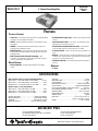
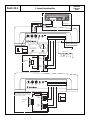
®
punch
2-channel amplifier
®
car audio
for
Installation Reference Sheet
Páginas de Referencia para la Instalación
Schéma d’Installation
Installations Beiblatt
Istruzioni di Installation
fanatics
®
Dear Customer,
Congratulations on your purchase of the world's finest brand of car audio electronics. At Rockford Fosgate we are
fanatics about musical reproduction at its best, and we are pleased you chose our product. Through years of engineering
expertise, hand craftsmanship and critical testing procedures, we have created a wide range of products that reproduce
music with all the clarity and richness you deserve.
For maximum performance we recommend you have your new Rockford Fosgate product installed by an Authorized
Rockford Fosgate Dealer, as we provide specialized training through Rockford Technical Training Institute (RTTI).
Please read your warranty and retain your receipt and original carton for possible future use.
Great product and competent installations are only a piece of the puzzle when it comes to your system. Make sure that
your installer is using 100% authentic installation accessories from Connecting Punch in your installation.
Connecting Punch has everything from RCA cables and speaker wire to Power line and battery connectors. Insist on
it! After all, your new system deserves nothing but the best.
To add the finishing touch to your new fanatic image order your Rockford Fosgate wearables, which include everything
from T-shirts and jackets to hats and sunglasses.
To get a free brochure on Rockford Fosgate products and Rockford wearables, please call 602-967-3565 or FAX 602967-8132. For International orders, FAX +001-1-602-967-8132 or call +001-1-602-967-3565.
PRACTICE SAFE SOUND™
CONTINUOUS EXPOSURE TO SOUND PRESSURE LEVELS OVER 100dB MAY CAUSE PERMANENT HEARING LOSS.
HIGH
POWERED AUTOSOUND SYSTEMS MAY PRODUCE SOUND PRESSURE LEVELS WELL OVER
130dB. USE
COMMON SENSE AND PRACTICE SAFE SOUND.
If, after reading your manual, you still have questions regarding this product, we recommend that you see your Rockford Fosgate dealer. If you
need further assistance, you can call us direct at 1-800-669-9899. Be sure to have your serial number, model number and date of purchase
available when you call.
The serial number can be found on the outside of the box. Please record it in the space provided below as your permanent record. This will
serve as verification of your factory warranty and may become useful in recovering your amplifier if it is ever stolen.
Serial Number: _____________________________________________
Model Number: ____________________________________________
–1–
Punch 45.2
Specification
Reference
Sheet
2-Channel Punch Amplifier
FEATURES
TECHNICAL FEATURES
• Trans•ana – Sound quality topology that sends an extended bandwidth
accurately to the output stages of the amplifier
• Gold-Plated RCA Input Jacks – Maintains signal quality by resisting
corrosion
• TOPAZ – Eliminates troublesome ground loop noise between the source
• Input Sensitivity Control – Level control can be adjusted to match
and amplifier
output levels from a variety of source units
• NOMAD – Extremely fast protection system that always protects the
• Gold-Plated Power/Speaker Barrier Strip – Screw terminals
amplifier and never degrades the sound
accept #10 spade lugs or bare wire sized from 10 to 18 AWG
• MOSFET Devices – Power supply and output devices that have high
• Crossover Switch – Crossover can be set for low-pass operation or full
thermal stability, fast switching speed, low output impedance, and wide
bandwidth linearity
range
• Bass EQ – The Bass EQ allows a narrow band adjustment of up to +18dB
• DSM (Discrete Surface Mount) Technology – Fewer
centered at 45Hz. The bass boost can be bypassed by turning the control to
its minimum or counterclockwise position
connections, improved reliability, shorter signal paths, superior signal-tonoise ratio and awesome sonic performance
• LED Power Indicator – Visual indicator illuminates when amplifier is
DESIGN FEATURES
turned on
WARRANTY
• Diecast Heatsink – Dissipates heat generated by the amplifier’s
circuitry
• 3 Years
SPECIFICATIONS
Slew Rate .................................................................... 30v/µs
IM Distortion (IHF) ..................................................... <0.05%
Input Impedance ............................................................ 20kΩ
Factory Default Crossover ............................ 80Hz low-pass fixed
Crossover Slope ................................... 12dB/octave Butterworth
Source Unit Compatibility (+15dB gain overlap) .......... 20V max.
Input Sensitivity (0dB gain overlap) .................... 200mV to 3.5V
Operating Voltage ........................................ +9V to +15.4V DC
External Battery Fuse ................................................ 20A (ATC)
Standby Current
700mA
Dimensions ...................................... 25⁄8"H x 95⁄8"W x 109⁄32"L
(6.6cm x 24.4cm x 26.1cm)
Weight ........................................................ 5.7 lbs. (2.58kg)
RMS Continuous Power @ 14.4V (Competition Standard)
Stereo into a 4Ω load (20Hz-20kHz, <0.05% THD) ......... 22.5x2
Stereo into a 2Ω load (20Hz-20kHz, <0.10% THD) ............ 45x2
Bridged into a 4Ω load (20Hz-20kHz, <0.10% THD) .......... 90x1
Dynamic Power @ 14.4V (IHF Standard)
Stereo into a 4Ω load (20Hz-20kHz, 1% THD) ................... 50x2
Stereo into a 2Ω load (20Hz-20kHz, 1% THD) ................... 85x2
Bridged into a 4Ω load (20Hz-20kHz, 1% THD) ............... 170x1
Signal-to-Noise Ratio ................................ >100dB (A-weighted)
Frequency Response .................................. 20Hz-20kHz ±0.5dB
Bandwidth .............................................. 10Hz-250kHz ±3.0dB
Damping Factor @ 4Ω ...................... >200 (at output connector)
ACCESSORY PACK
(1) Punch Verification Certificate
(4) Amplifier Mounting Screws (#8 x 3/4” Phillips)
(1) 9/64” Allen Wrench
®
(4) 9/64” End Cap Mounting Screws
(1) ATC In-line Fuseholder
(1) ATC 20 Amp Fuse
Specifications subject to change without notice
®
–2–
Punch 45.2
Installation
Reference
Sheet
2-Channel Punch Amplifier
R
AUD
VOL
PWR
®
CLOCK
AUTO
ILLUM
DSPL
P.SCN
LOUD
SEL
D.SCN
SCAN
RPT
RDM
DIM
PAUSE
1
2
3
4
5
6
TUNE
®
Extension RCA's (opt.)
Remote Turn-On
LED
Full 80Hz LP
Range Xover Left
Input
®
80Hz Low-Pass
Xover Frequency
0dB
–3dB
L–
R+
R–
B+
REM
GND
+18
+12
+6
+3
0dB
Full Range
Xover Frequency
33Hz
20Hz
L+
®
0dB
–3dB
80Hz
Gain
Bass
EQ
Right
Input
45Hz
67.5Hz
33Hz
45Hz
67.5Hz
Battery +12V
+
20kHz
Stereo 2 or 4 ohm
Bridged/Mono 4 ohm
20A
Fuse
Less than 18"
+
Left (+)
+
Left
Speaker
Bridged/Mono
Woofer
–
+
–
Right
Speaker
Right (–)
–
LED
Full 80Hz LP
Range Xover Left
Input
Right
Input
®
Bass
EQ
Gain
L+
L–
R+
R–
B+
REM
GND
®
Simultaneous Bridged/Mono 4 ohm with Stereo 2 or 4 ohm
Use passive crossovers when running amplifier in
Stereo & Bridged/Mono mode simultaneously. Please
contact your Authorized Rockford Fosgate Dealer for
information on passive crossovers.
Left
Speaker
Bridged/Mono
Woofer
0dB
–3dB
–
+
–
Full Range
Xover Frequency
+
Left (+)
+
Set crossover switch for Full Range only
Right
Speaker
–
Right (–)
–3–
20Hz
20kHz
–
Battery
INSTALLATION
• For safety, disconnect the negative lead from the car battery prior to beginning the installation
Trunk Mounting
Mounting the amplifier vertically on a surface with the fin grooves running up and down will provide the best cooling for the amplifier.
Passenger Compartment Mounting
Mounting the amplifier in the passenger compartment will work as long as you provide a sufficient amount of air for the amplifier to cool
itself. If you are going to mount the amplifier under the seat of the vehicle, you must have at least 1” (2.54cm) of air gap around the
amplifier’s heatsink.
B+ Terminal
The B+ cable MUST be fused 18” (45cm) or less from the vehicle’s battery. Prepare the cable ends and install the fuseholder under the
hood. Connections should be water tight.
GND Terminal
Prepare a length of cable to be used for the ground connection. Prepare the chassis ground by scraping any paint from the metal surface
and thoroughly clean the area of all dirt and grease. Fasten the cable to the chassis using a screw.
REM Terminal
Connect the REM wire to a switched 12 volt positive source. The switched signal is usually taken from the source unit’s auto antenna or
the accessory lead. If the source unit does not have these outputs available, the recommended solution is to wire a mechanical switch inline with a 12 volt source to activate the amplifier.
Input Connectors
Follow the diagram and connect the appropriate signal cables to the input terminals of the amplifier. Be sure that the signal cables are
routed close together and away from any high current wires.
Speaker Output Terminals
Connect the speaker system to the amplifier by inserting the wires into the corresponding output terminals and tighten the set screws.
Follow the diagram for proper signal polarity. DO NOT chassis ground any of the speaker wires as unstable amplifier operation may
result. CAUTION: This amplifier is not recommended for impedance loads below 2Ω stereo and/or 4Ω bridged (mono).
Gain Control(s)
The amplifier is factory set for optimum dynamic range. The system levels may be adjusted by ear when using a source unit with higher or
lower output levels by using the following procedure.
1. Turn the gain control to minimum (counterclockwise)
2. Play a music track with high dynamic content and turn up the source unit to at least 3/4 volume
3. Slowly increase the gain and set it just below audible distortion or until reaching a comfortable hearing threshold (whichever occurs
first)
TROUBLESHOOTING
Symptom
Amplifier does not turn on.
Amplifier Noise
(Turn-On Pop)
Engine Noise
Diagnosis
Remedy
B+ or REM not between 10.5 and 15.5 volts or
no voltage present
Check the alternator, battery, fuse, and
wiring and repair as necessary
Amplifier is not properly grounded.
Check wiring and repair as necessary
Voltage spike from source unit is entering
amplifier’s input
Connect turn-on module to REM terminal if
pops are eliminated with no input signal to
amplifier
Noise is radiating into signal cables
Re-route signal cables away from sources
of high current
–4–
Punch 45.2
Páginas de Referencia
para la Instalación
Amplificadore de Punch a 2 canale – Español
R
AUD
VOL
PWR
®
CLOCK
AUTO
DSPL
P.SCN
SEL
ILLUM
LOUD
D.SCN
SCAN
RPT
RDM
DIM
PAUSE
1
2
3
4
5
6
TUNE
®
Extension de RCA (opcional)
Encendido Remoto
LED
Full 80Hz LP
Range Xover Left
Input
®
80Hz Low-Pass
Xover Frequency
0dB
–3dB
L–
R+
R–
B+
REM
GND
+18
+12
+6
+3
0dB
Full Range
Xover Frequency
33Hz
20Hz
L+
®
0dB
–3dB
80Hz
Gain
Bass
EQ
Right
Input
45Hz
67.5Hz
33Hz
45Hz
67.5Hz
Batería +12V
20kHz
+
Estéreo 2 ó 4 Ohmios
4 Ohmios Mono/Puente
Fusible de
20 amperios
Menos de
45cm
+
Izquierda (+)
+
Parlante
Izquierdo
Batería
–
Bajo
Mono/Puente
+
–
Parlante
Derecho
Derecha (–)
–
LED
Full 80Hz LP
Range Xover Left
Input
®
Right
Input
Bass
EQ
Gain
L+
L–
R+
R–
B+
REM
GND
®
4 Ohmios Mono/Puente con estéreo 2 ó 4 Ohmios
Set crossover switch for Full Range only
Use divisores pasivos de frecuencia cuando el
ampificador esté trabajando en Estéreo y
Mono/Puente simultá neamente.
Izquierda (+)
+
Bajo
Mono/Puente
Full Range
Xover Frequency
+
0dB
–3dB
Parlante
Izquierdo
20Hz
–
+
–
Parlante
Derecho
Derecha (–)
–
–5–
20kHz
–
INSTALACÍON
• Por seguridad, desconecte el terminal negativo de la bateria antes de comenzar la instalacíon.
Montaje en el Malatero del vehícule
Monte el amplificador verticalmente con las líneas del radiador orientadas de arriba hacia abajo. De esta manera conseguirá la mejor
ventilación.
Montaje en el Compartimento de Pasajeros
El montaje en el compartimento de pasajeros sera eficiente en funcion de la ventilación que tenga el amplificador. Si va a instalar el
amplificador bajo un asiento deberá dejar al menos 2.5cm libres sobre la carcasa del amplificador.
Terminal B+
El cable B+ debe ir provisto de un fusible a una distancia no mayor de 45cm de la batería. Prepare el cable e instale el portafusibles en
el compartimento del motor. Las conexiones han de ser impermeables.
Terminal GND
Prepare un trozo de cable para usarlo como toma de masa. Prepare un punto de masa en el chasis rascando y eliminando la pintura de
la superfcicie de metal y límpielo de toda suciedad asegure el cable al chasis con un tornillo.
Terminal REM (Encendido remoto)
Conecte el cable REM a un punto de +12V conmutable. La señal se suele coger de la salida auto antena del radio cassette si este no
tiene salida remote.
Conectores de Entrada
Siga el diagrama y conecte los cables adecuados para señal a los terminales de entrada del amplificador. Asegúre se que los cables de
señal esten canalizados en conjunto y lo más lejo posible de cualquier cable de alto amperaje.
Terminales de salida para los Parlantes
Conecte el sistema de parlantes al amplificador insertando los cables correspondientes en los ternminales de salida y luego aprete los
tornillos. Siga el diagrama para una adecuada polaridad de señal. NO CONECTE ninguno de los cables de los parlantes a la masa de
la carcasa, ya que esto puede resultar en una operación inestable del amplificador. PRECAUCION: este amplificador no está
recomendado para cargas de impedancia por abajo de 2 Ohmios en estéreo y/ó 4 Ohmios en modo puente (bridge mono).
Control(es) de Ganancia
El amplificador está dispuesto desde la fábrica para óptimo rango dinámico. Los niveles del sistema pueden ser ajustado por oído
cuando se utilice una unidad fuente con niveles de salidas más altos ó bajos, mediante el uso del siguiente procedimiento:
1. Lleve el control de ganancia al mínimo (en contra de las agujas del reloj)
2. Reproduzca una pista musical con alto contemiodo dinámico y lleve el volumen de la unidad fuente hasta unos 3/4 de máximo
3. Lentamente incremente la ganancia y pare justo bajo el nivel audible de distorsion ó hasta que llegue a un umbral agradable de
audición (cualquiera que ocurra primero)
TROUBLESHOOTING
Síntoma
El Amplificador no enciende
Ruido de Amplificador
(Popeo de encendido)
Ruido de Motor
Diagnóstico
Remedio Reparación
B+ ó REM no están entre 10.5 y 15.5 voltios ó no hay
voltaje presente.
Chequee el alternador, batería, fusible y cableado
y repare segun sea necesario
El amplificador no está aterrado apropiademente
Cheque el cableado y repare según sea necesario
Picos de voltaje de la unidad fuente están presentes en
la entrada del amplificador
Conecte el módulo de encendido al terminal
REM si el popeo es eliminado cuando el
amplificador no tiene señal de entrada
Ruido está siendo radiado en los cables de señal
Recanlizar los cables de señal aleajado de
fuentes de alto amperaje
–6–
Punch 45.2
Schéma
d’Installation
Amplificateur de puissance 2 canaux– Français
R
AUD
VOL
PWR
®
SEL
CLOCK
AUTO
ILLUM
DSPL
P.SCN
LOUD
D.SCN
SCAN
RPT
RDM
DIM
PAUSE
1
2
3
4
5
6
TUNE
®
Extension RCA (en option)
Câble de télécommande
LED
Full 80Hz LP
Range Xover Left
Input
®
80Hz Low-Pass
Xover Frequency
0dB
–3dB
L–
R+
R–
B+
REM
GND
+18
+12
+6
+3
0dB
Full Range
Xover Frequency
33Hz
20Hz
L+
®
0dB
–3dB
80Hz
Gain
Bass
EQ
Right
Input
45Hz
67.5Hz
33Hz
45Hz
67.5Hz
Batterie +12V
+
20kHz
Stéréro 2 ou 4 Ohms
Ponté/Mono 4 Ohms
Fusible
20A
Moins de 45cm
+
Gauche (+)
+
Biport/Mono
Woofer
Hautparleur
gauche
–
+
–
Hautparleur
droit
Droit (–)
–
LED
Full 80Hz LP
Range Xover Left
Input
Right
Input
®
Bass
EQ
Gain
L+
L–
R+
R–
B+
REM
GND
®
Ponté/Mono 4 ohm avec Stéréo 2 ou 4 ohm
Dans le cas d'une utilisation trimode stéréo speaker
+ mono subwoofer, l'utilisation de filtres passifs est
impérative. Important: dans cette utilisation, la XCard
est en position large bande.
Set crossover switch for Full Range only
Full Range
Xover Frequency
+
Gauche (+)
Hautparleur
gauche
+
Ponté/Mono 4
Ohms
0dB
–3dB
20Hz
–
+
–
Hautparleur
droit
–
Droit (–)
–7–
20kHz
–
Batterie
INSTALLATION
• Pour votre sécurité, deéconnectez la borne négative de la batterie du véhicule avant de commencer le montage.
Montage dans l’habitacle
L’installation d’un amplificateur est envisageable dans l’habitacle dès que la convection naturelle est suffisante. Il est possible de fixer
l’amplificateur soud un siège si la hauteur de celui-ci permet au minimum d’avoir trois centimètres au-dessus du dissipateur thermique.
Alimentation
La connexion B doit être reliée impérativement via un fusible, directement à la borne positive de la batterie.
La connexion GND
Cette liaison référence l’amplificateur à la masse. La masse électrique du châssis n’a pas en tous points la même qualité. Il vous sera utile
de recourir aux compétences d’un professionel pour déterminer le meilleur point. Une fois trouvé, il faudra débarrasser la tôle de toutes
traces de peinture, le raccordement devra se faire par une vis acier (sans traitement de surface).
La connexion REM
Cette connexion est la commande à distance de mise en/hors service. Elle est généralement reliée à la sortie (antenne électrique de
l’autoradio) ou auprès d’une source de douze volts commutée.
Connecteur CINCH
Cette liaison assure la transmission de modulation entre l’autoradio et la source. En raison des faibles signaux véhiculés dans ces câbles,
ceux-ci devront être tenus à l’écart du faisceau électrique du véhicule et des câbles d’alimentation de l’amplificateur.
Connections haut-parleurs
Les haut-parleurs serons connectés sur cette partie du bornier. Soyez vigilant quant au sens du branchement + et –. Avertissement:
L’impédance globale en mode stéréo ne peut être inférieure à deux Ω et en mode ponté à quatre Ω.
Contrôle de sensibilité
A la sortie d’usine, l’amplificateur est réglé (valeur qui détermine la meilleure capacité dynamique). La sensibilité est variable pour
adapter l’amplificateur aux différentes sources qui ne possèdent pas le même niveau de sortie. Ce réglage est très important, il est
déterminant de la qualité de reproduction et de la pérennité de l’installation.
Méthodologie du réglage
1. Positionnez le réglage de sensibilité au minimum (à l’inverse du sens des aiguilles d’une montre)
2. Ecoutez un passage musical à grande dynamique (solo de guitare basse, etc.) avec le potentiomètre de volume de la source aul 3/4
3. Doucement dans le sens des aiguilles d’une montre tournez le potentiomètre de sensibilité de l’amplificateur jusqu’à percevoir une
déformation. A cette étape, il fault revenir juste en-dehors du seuil de déformation
4. Il faut répéter plusieurs fois cette procédure avec différents disques pour être sûr du réglage
SOLUTIONS AUX PROBLÈMES
Symptôme
Diagnostic
Solution
L’amplificateur ne
fonctionne pas
B+ our REM ne sont pas connectés à une source
de 12V
Vérifiez si la batterie est reconnectée et si le
fusible est bon
Bruit à l’a mise en/hors service
Le bruit est transmis par la source
Insérez un module séparé de télécommande
commandant l’amplificateur
Bruit rayonné sur les câbles de modulation
Tenir à l’écart les câbles de modulation du
faisceau électrique de la voiture et de
l’alimentation de l’amplificateur
Bruit parasite
–8–
Punch 45.2
Installations
Anleitung
2-Kanal Punch Amplifier – Deutsch
R
AUD
VOL
PWR
®
CLOCK
AUTO
DSPL
P.SCN
SEL
ILLUM
LOUD
D.SCN
SCAN
RPT
RDM
DIM
PAUSE
1
2
3
4
5
6
TUNE
®
Verlängerungskabel
(Optional)
Remote-Kabel
LED
Full 80Hz LP
Range Xover Left
Input
®
80Hz Low-Pass
Xover Frequency
0dB
–3dB
L–
R+
R–
B+
REM
GND
+18
+12
+6
+3
0dB
Full Range
Xover Frequency
33Hz
20Hz
L+
®
0dB
–3dB
80Hz
Gain
Bass
EQ
Right
Input
45Hz
67.5Hz
33Hz
45Hz
67.5Hz
Batterie +12V
+
20kHz
Stereo 2 or 4 ohm
Gebrueckt/Mono 4 ohm
20A
Sicherung
+
Links (+)
+
Batterie
Weniger als 45cm
Linker
Lautsprecher
–
Gebrueckt/Mono
Woofer
+
–
Rechter
Lautsprecher
Rechts (–)
–
LED
Full 80Hz LP
Range Xover Left
Input
Right
Input
®
Bass
EQ
Gain
L+
L–
R+
R–
B+
REM
GND
®
Simultaneous Bridged/Mono 4 ohm with Stereo 2 or 4 ohm
Benutzen Sie passive Weichen, wenn Sie den Verstärker
im Trimode-Betrieb nutzen. Bitte informieren Sie sich bei
Ihrem autorisierten Rockford Fosgate Händler ueber passive
Frequenzweichen.
+
Set crossover switch for Full Range only
Full Range
Xover Frequency
+
Links (+)
Linker
Lautsprecher
Gebrueckt/Mono
Woofer
0dB
–3dB
20Hz
–
+
–
Rechter
Lautsprecher
–
Rechts (–)
–9–
–
20kHz
EINBAU
• Zur Sicherheit klemmen Sie den Negativ-Pol der Batterie während des gesamten Einbaues ab.
Im Fahrzeugkofferraum
Der vertikale Einbau der Endstufen, das bedeutet, dab die Kühlrippen von oben nach unten verlaufen, gibt dem Verstärker die beste Kühlung.
Auf der Beifahrerseite
Sollte der Verstärker auf der Beifahrerseite montiert werden, so ist es sehr wichtig für eine ausreichende Kühlung zu sorgen. Sollte der Verstärker z.B. unter
dem Beifahrersitz montiert werden, sollte dem Kühlkörper mindestens ein Luftspalt von 3 cm bleiben, um so für eine ausreichende Kühlung zu sorgen.
B+ Anschluβ
Die Plus-Leitung MUβ ca. 40 cm nach dem Plus-Pol der Batterie abgesichert sein. Preparieren Si die Kabellängen und montieren Sie den
Sicherungshalter im Motorraum. ALLE Verbindungen müssen wasserdicht sein.
GND Anschluβ
Preparieren Sie Ihr Kabel für Negativ Leitung (Erdung). Preparieren Sie die Anschlubstelle des Erdungskabels, indem Sie das Metall gründlich reinigen
und vom Lack befreien. Befestigen Sie nun die Erdung an dieser Stelle mit einer Schraube.
REM Anschluβ
Verbinden Sie das Ein-und Ausschaltungskontroll-Kabel mit Ihrem Radio (12 Volt positiv). Normalerweise verwenden Sie hierfür die Ant.-Remote). Sollte
Ihr Radio diesen Anschluβ nicht besitzen, so verwenden Sie eine 12 Volt Spannung, die Sie durch einen Schalter ein- und ausschalten können.
Eingangs-Anschlüβe
Beachten Sie den Anschlussplan und verbinden Sie die Signalkabel mit den Eingangs-Anschluessen des Verstärkers. Seien Sie sicher, dass die Kabel dicht
zusammen und entfernt von stromfuehrenden Kabeln liegen.
Lautsprecher Ausgänge
Verbinden Sie das Lautsprechersystem mit dem Verstärker, indem Sie die Kabel in die entsprechenden Anschluesse stecken und verschrauben. Beachten
Sie hierbei den Anschlussplan, um eine korrekte Polarität zu gewährleisten. Erden Sie niemals eine der Lautsprecherleitung auf die Masse des
Fahrzeuges. Achtung: Die minimale Last von 2Ω Stereo und/oder 4Ω gebrueckt (Mono) darf nicht unterschritten werden.
Eingangsempfindlichkeit
Der Verstärker ist Werkssetig auf eine Eingangsspannung. Die Eingangsempfindlichkeit kann nach Gehoer verstellt werden, wenn die Ausgangsspannung
des Steuergerätes hoeher oder niedriger ist. Gehen Sie wie folgt vor.
1. Drehen Sie die Eingangsempfindlichkeit auf ein Minimum (gegen den Uhrzeigersinn).
2. Speilen Sie einen Musiktitel mit einer sehr hohen Dynamik und drehen Sie die Lautstärkekontrolle des Steuergerätes auf ä der Maximallautstärke.
3. Jetzt verstellen Sie die Eingangsempfindlichkeit des Verstärkers soweit (im Uhrzeigersinn drehen), bis Sie eine Verzerrung des Signals wahrnehmen.
Danach sollte ie Empfindlichkeit wieder soweit zurueck gedreht werden (gegen den Uhrzeigersinn), bis die Verzerrungen verschwindern.
F EHLERSUCHE
Syptom
Diagnose
Fehlerbehebung
Die B+ oder Rem. Spannung liegt nicht zwischen
10.5 und 15.5 Volt
Kontrollieren Sie die Lichtmaschine, Batterie,
Sicherung und die Kable. Repaireren Sie diese,
wenn noetig
Verstärker ist nicht korrekt geerdet
Kontrollieren Sie die Kabel und reparieren Sie
diese, wenn noetig
Verstärker Einschaltgeräusch
(Turn-On Pop)
Die XCard ist falsch oder gar nicht in den
entsprechenden Socket gesteckt.
Kontrollieren Sie die Installation der XCard und
ändern Sie diese, wenn noetig
Lichtmaschinen Summen
Stoerungen strahlen in die Signalkabel
Verlegen Sie die Kabel weit entfernt von stromfuehr
Verstärker schaltet nicht ein
– 10 –
Punch 45.2
Istruzinoni di
Installazione
Amplificatore di Punch a 2 canali – Italiano
R
AUD
VOL
PWR
®
CLOCK
AUTO
DSPL
P.SCN
SEL
ILLUM
LOUD
D.SCN
SCAN
RPT
RDM
DIM
PAUSE
1
2
3
4
5
6
TUNE
®
Prolunga RCA (opzionale)
Accensione
LED
Full 80Hz LP
Range Xover Left
Input
®
80Hz Low-Pass
Xover Frequency
0dB
–3dB
L–
R+
R–
B+
REM
GND
+18
+12
+6
+3
0dB
Full Range
Xover Frequency
33Hz
20Hz
L+
®
0dB
–3dB
80Hz
Gain
Bass
EQ
Right
Input
45Hz
67.5Hz
33Hz
45Hz
67.5Hz
Batteria +12V
20kHz
+
–
Stereo a 2 o 4 ohm
Mono a ponte 4 ohm
Fusibile da
20 Ampere
+
sinistro (+)
Altoparlante
sinistro
+
Batteria
Meno di 45 centimetri
–
Woofer mono
a ponte
+
–
Altoparlante
destro
destro (–)
–
LED
Full 80Hz LP
Range Xover Left
Input
Right
Input
®
Bass
EQ
Gain
L+
L–
R+
R–
B+
REM
GND
®
Simultaneous Bridged/Mono 4 ohm with Stereo 2 or 4 ohm
Set crossover switch for Full Range only
Impiegando il funzionamento stereo-mono
simultaneo é richiesto l'impiego di un crossover
sinistro (+)
+
Woofer mono
a ponte
Full Range
Xover Frequency
+
0dB
–3dB
Altoparlante
sinistro
20Hz
–
+
–
Altoparlante
destro
destro (–)
–
– 11 –
20kHz
INSTALLAZIONE
• Per sicurezza, scollegare il polo netativo della batteria dell’auto prima di iniziare l’installazione.
Nel Bagagliaio
Montando l’amplificatore su una superficie in verticale con le alette direzionate dall’alto verso il basso si garantirá un miglior
raffreddamento dell’amplificatore.
Nel’abitacolo
Montare l’amplificatore nell’abitacolo si avrá un funzionamento regolare se si garantisce un flusso d’aria sufficiente. Per l’installazione
sotto un sedile, é necessario avere uno spazio di almeno 3 cm attorno a tutto l’amplificatore.
Terminale B+ (cavo positivo)
Il cavo positivo deve essere protetto da un fusibile a non piú di 45 cam dalla batteria. Terminare il cavo e installare il fusibile nel vano
motore. Tutte le connessioni devono essere a prova d’acqua.
Terminal GND (cavo negativo)
Decidere la lunghezza del cavo e terminarlo. Preparare la massa grattando la vernice dal telaio dell’auto ed eliminando tracce di olio o
sporco. Fissare il cavo di massa al telaio con una vite.
Terminal REM (Consenso di accensione)
Collegare il cavo REM ad un positivo present solo ad autoradio accessa (normalmente il cavo pilota dell’antenna elettrica o il cavo
accessori dell’autoradio). Se la sorgente non dovesse essere equipaggiata con queste uscite, la soluzione raccomandabile é di inserire un
interruttore su un cavo positivo e connettersi all’amplificatore.
Connettori di ingresso
Seguendo lo schema collegate i cavi di segnale agli appropriati terminali di ingresso dell’amplificatore. Assicuratevi che i cavi di segnale
siano passati vicini tra loro e lontano da cavi ad alta corrente.
Connettori degli altoparlanti
Collegate il sistema di altoparlanti inserendo i cavi nei terminali corrispondenti e serrate le viti. Seguite lo schema per l’ottimale colle
gamento delle polaritá. Non cortocircuitate a massa nessun cavo degli altoparlanti, potrebbe verificarsi un anomalo comportamento
dell’amplificatore. ATTENZIONE; questo amplificatore non é raccomandato per impedenze inferiori ai 2 ohm stereo w/o 4 ohm
mono a ponte.
Controlli della sensibilitá
L’amplificatore é regolato dalla casa per un ottimale rendimento dinamico. Il lilvello di ingresso puó essere regolato anche ad orecchio
quando si impiega una sorgente con uscita superiore od inferiore. Seguite questa procedure:
1. Portate il controllo della sensibilitá al minimo (senso antiorario)
2. Suonate un brano musicale con elevato contenuto dinamico portando il volume della sorgente a circa 3/4
3. Aumentate lentamente il livello di ingresso dell’amplificatore e posizionatelo subito prima dell’insorgere di distorsione o quando il
livello generale vi appaia confortevole
RISOLUZIONE DEI PROBLEMI
Sintomo
Diagnosi
Rimendo
Il B+ o il REM n on hanno una tensione
compresa tra i 10,5 e 15,5 volt o nessuna
tensione é presente
Verficate l’alternatore, la batteria, i fusibilit,
il cablaggio e riparate quanto necessario
L’amplificatore non é correttamente a massa
Controllate il cablaggio e riparat se
necessario
Rumore dell’amplificatore
(bump di accensione)
Picchi di tensione provenienti dalla sorgente
entrano dall’ingresso dell’amplificatore
Se il bump si elimina disconnettendo gli
ingressi, collegate un modulo di accensione
Rumore dal motore
Il rumore si propagna nei cavi di segnale
Ristendete i cavi di segnale lontano da cavi
ad alta corrente
L’ampificatore non si accende
– 12 –
ENGLISH
Please contact your local Authorized
Rockford Fosgate Dealer for information
on Warranty Policies and Technical Support.
ESPAÑOL
Por favor contacte al Distribuidor Autorizado Rockford
Fosgate en su localidad para información sobre Políticas
de Garantía Soporte Técnico.
DEUTSCH
Bitte Fragen Sie Ihren autorisierten Rockford Fosgate Händler
über Informationen, die die Garantie oder technische Probleme
betreffen.
FRANÇAIS
Veuillez contacter votre distributeur Rockford Fosgate
agréé pour toute information concernant les
modalités de garantie et le support technique.
ITALIANO
Contattate il vostro rivenditore autorizzato Rockford
Fosgate per informazioni sulle condizioni di garanzia
e per il supporto tecnico.
LIMITED W ARRANTY I NFORMATION
Rockford Corporation offers a limited warranty on Rockford Fosgate products on the following terms:
• Length of Warranty
3 years on electronics
2 years on source units
90 days on electronic B-stock (receipt required)
30 days on speaker B-stock (receipt required)
• What is Covered
This warranty applies only to Rockford Fosgate products sold to consumers by Authorized Rockford Fosgate Dealers in the United States
of America or its possessions. Product purchased by consumers from an Authorized Rockford Fosgate Dealer in another country are covered
only by that country’s Distributor and not by Rockford Corporation.
• Who is Covered
This warranty covers only the original purchaser of Rockford product purchased from an Authorized Rockford Fosgate Dealer in the United
States. In order to receive service, the purchaser must provide Rockford with a copy of the receipt stating the customer name, dealer name,
product purchased and date of purchase.
• Products found to be defective during the warranty period will be repaired or replaced (with a product deemed to be equivalent) at
Rockford's discretion.
• What is Not Covered
1. Damage caused by accident, abuse, improper operations, water, theft
2. Any cost or expense related to the removal or reinstallation of product
3. Service performed by anyone other than Rockford or an Authorized Rockford Fosgate Service Center
4. Any product which has had the serial number defaced, altered, or removed
5. Subsequent damage to other components.
6. Any product purchased outside the U.S.
7. Any product not purchased from an Authorized Rockford Fosgate Dealer
• Limit on Implied Warranties
Any implied warranties including warranties of fitness for use and merchantability are limited in duration to the period of the express warranty
set forth above. Some states do not allow limitations on the length of an implied warranty, so this limitation may not apply. No person is
authorized to assume for Rockford Fosgate any other liability in connection with the sale of the product.
• How to Obtain Service
Please call 1-800-669-9899 for Rockford Customer Service. You must obtain an RA# (Return Authorization number) to return any product
to Rockford Fosgate. You are responsible for shipment of product to Rockford.
Ship to: Electronics
Rockford Corporation
Warranty Repair Department
2055 E. 5th Street
Tempe, AZ 85281
RA#:_________________
Ship to: Speakers
Rockford Acoustic Design
(Receiving-speakers)
609 Myrtle N.W.
Grand Rapids, MI 49504
RA#:_________________
MADE IN THE USA
This product is designed, developed and assembled in the USA by a dedicated group of
American workers. The majority of the components used in the construction of this product
are produced by American companies. However, due to the global nature of their
manufacturing facilities and the electronics parts industry in general, some parts may be
manufactured in other countries.
Rockford Fosgate
MAN-1848-A
9/97
Rockford Corporation
546 South Rockford Drive
Tempe, Arizona 85281 U.S.A.
In U.S.A., (602) 967-3565
In Europe, Fax (49) 850-3934-014
In Japan, Fax (81) 559-79-1265