1
1
Midisport 8x8 ™
MANUAL
version: MS8-09092000
Table of Contents
Introduction . . . . . . . . . . . . . . . . . . . . . . . . . . . . . . . . . . . . . . . . . . . . . . . . . . .2
Features . . . . . . . . . . . . . . . . . . . . . . . . . . . . . . . . . . . . . . . . . . . . . . . . . . . . . .2
Package Contents . . . . . . . . . . . . . . . . . . . . . . . . . . . . . . . . . . . . . . . . . . . . . . .3
Product Layout . . . . . . . . . . . . . . . . . . . . . . . . . . . . . . . . . . . . . . . . . . . . . . . .3
Front Panel . . . . . . . . . . . . . . . . . . . . . . . . . . . . . . . . . . . . . . . . . . . . . . . .3
Back Panel . . . . . . . . . . . . . . . . . . . . . . . . . . . . . . . . . . . . . . . . . . . . . . . .4
Overview . . . . . . . . . . . . . . . . . . . . . . . . . . . . . . . . . . . . . . . . . . . . . . . . . . . . .5
Quick Guide to Getting Started . . . . . . . . . . . . . . . . . . . . . . . . . . . . . . . . . . . .6
Hardware Installation . . . . . . . . . . . . . . . . . . . . . . . . . . . . . . . . . . . . . . . . . . .7
Driver Software Installation . . . . . . . . . . . . . . . . . . . . . . . . . . . . . . . . . . . . . .8
MIDI Interface Modes . . . . . . . . . . . . . . . . . . . . . . . . . . . . . . . . . . . . . . . . . .17
Stand-Alone Modes . . . . . . . . . . . . . . . . . . . . . . . . . . . . . . . . . . . . . . . . . . . .18
MIDISPORT Mode Assignments . . . . . . . . . . . . . . . . . . . . . . . . . . . . . . . . .19
USB Mode . . . . . . . . . . . . . . . . . . . . . . . . . . . . . . . . . . . . . . . . . . . . . . .19
PC Mode . . . . . . . . . . . . . . . . . . . . . . . . . . . . . . . . . . . . . . . . . . . . . . . . .20
Mac Mode . . . . . . . . . . . . . . . . . . . . . . . . . . . . . . . . . . . . . . . . . . . . . . . .20
Cable Test Mode . . . . . . . . . . . . . . . . . . . . . . . . . . . . . . . . . . . . . . . . . . .21
Thru Mode . . . . . . . . . . . . . . . . . . . . . . . . . . . . . . . . . . . . . . . . . . . . . . .21
Patchbay Operation . . . . . . . . . . . . . . . . . . . . . . . . . . . . . . . . . . . . . . . .22
SMPTE Operation . . . . . . . . . . . . . . . . . . . . . . . . . . . . . . . . . . . . . . . . . . . . .22
SMPTE Writer . . . . . . . . . . . . . . . . . . . . . . . . . . . . . . . . . . . . . . . . . . . .23
SMPTE Reader . . . . . . . . . . . . . . . . . . . . . . . . . . . . . . . . . . . . . . . . . . . .23
SMPTE "Write" Button . . . . . . . . . . . . . . . . . . . . . . . . . . . . . . . . . . . . .24
SMPTE "Format" Button . . . . . . . . . . . . . . . . . . . . . . . . . . . . . . . . . . . .25
Setting Up Your MIDI Studio . . . . . . . . . . . . . . . . . . . . . . . . . . . . . . . . . . . .25
Typical MIDI System Set-up: . . . . . . . . . . . . . . . . . . . . . . . . . . . . . . . . .25
Using the MIDISPORT in your Application Software . . . . . . . . . . . . . . . . .27
MIDISPORT Remote Control Software . . . . . . . . . . . . . . . . . . . . . . . . . . . .28
Remote Control Operation . . . . . . . . . . . . . . . . . . . . . . . . . . . . . . . . . . . . . . .29
Windows Menus . . . . . . . . . . . . . . . . . . . . . . . . . . . . . . . . . . . . . . . . . . . . . .30
Macintosh Menus . . . . . . . . . . . . . . . . . . . . . . . . . . . . . . . . . . . . . . . . . . . . .32
Remote Control Patchbay Operation . . . . . . . . . . . . . . . . . . . . . . . . . . . . . . .34
Diagnostics Software . . . . . . . . . . . . . . . . . . . . . . . . . . . . . . . . . . . . . . . . . . .36
Test Results for Mac or PC . . . . . . . . . . . . . . . . . . . . . . . . . . . . . . . . . . . . . .38
SMPTE/MIDI Time Code Tutorial . . . . . . . . . . . . . . . . . . . . . . . . . . . . . . . .40
Before Calling Tech Support . . . . . . . . . . . . . . . . . . . . . . . . . . . . . . . . . . . . .49
Limited Lifetime Warranty . . . . . . . . . . . . . . . . . . . . . . . . . . . . . . . . . . . . . .50
Introduction
Thank you for purchasing the MIDISPORT™ 8x8/s multi-port MIDI interface
for USB equipped PC and Macintosh computers. The MIDISPORT’s high speed
Universal Serial Bus connection to the computer assures reliable and speedy
transfer of MIDI data. The MIDISPORT 8x8/s can also be connected to the serial
port of PCs and “legacy” Macintosh computers.
The MIDISPORT performs SMPTE read/write functions using either the front
panel control switches or the included remote control software, which will also
control patchbay settings for your new MIDISPORT 8x8/s.
Follow the installation instructions in this manual and you will be up and
running in no time. The MIDISPORT installs externally to your computer,
requiring no computer disassembly. Expansion is easy too — just plug in
additional MIDISPORT units for more MIDI ports (USB only).
Features
The MIDISPORT 8x8/s USB MIDI Interface has the following features:
•
8 independent in / 8 independent out MIDI Interface (128x128 MIDI
channels) in professional 19" single height rack mount chassis.
•
High-speed connection to USB-equipped PC or Mac computers.
•
Alternate "legacy" serial connection to non-USB PC or Mac computers.
•
MIDI in and out activity indicators for each port.
•
Includes 6 ft. USB cable.
•
When disconnected from the PC, unit operates as a stand-alone MIDI
patchbay, as well as a SMPTE to MTC synchronizer.
•
Built-in "MIDI cable tester" mode.
•
Windows 98 compatible -- true Plug-and-Play installation requires no IRQ,
I/O Address or DMA channel setup
•
Mac OMS Compatible. Works with Mac OS 8.6 and above.
•
Includes Windows and Mac Control Panel software.
SMPTE Time Code Writer/Reader
•
•
•
•
Reads and writes 24, 25, 29.97, 30 drop or 30 non-drop frame LTC SMPTE
formats.
Any SMPTE time write offset may be set-up via included control panel
software
Converts LTC SMPTE to MIDI Time Code (MTC) for syncing any MTC
capable software.
Selectable "flywheel" that can be set to any value from 1 frame to 255 frames,
or infinite flywheel.
2
•
Can perfectly regenerate even the worst SMPTE Time Code.
•
Performs "JAM" sync in all modes.
Please read the installation instructions thoroughly before physically installing
your MIDISPORT 8x8/s. For software driver installation information please
refer to the section “Software Installation.”
Package Contents
Included in the MIDISPORT 8x8/s package are:
• This manual.
•
MIDISPORT 8x8/s Interface.
•
1 Standard USB A/B Cable for Mac or PC.
•
1 serial adapter cable for the PC.
•
1 Power Supply, 9V DC 500mA "wall wart."
•
Driver Software diskette/CD for Windows 95/98/2000 and MacOS. The CD
also includes Opcode’s OMS v.2.3.7 for use with MacOS.
IMPORTANT: IF YOU RECEIVED A FLOPPY DISK INSTEAD OF A
CD, USE THE INSTALLATION INSTRUCTIONS AND DRIVERS ON
THE FLOPPY DISK. All of the latest driver software, including
Opcode’s OMS, is also downloadable from our website at
www.midiman.net - Click on the “Drivers” page, then select
“MIDISPORT 8x8/s.”
Product Layout
Front Panel
1. MIDI In 8 - This standard MIDI jack connects the MIDISPORT Port 8 input to
the output of a MIDI device using a standard MIDI cable.
2. MIDI Out 8 - This standard MIDI jack connects the MIDISPORT Port 8
output to the input of a MIDI device using a standard MIDI cable.
3. MIDI Reset button - This button, when pressed, acts as a "panic button,"
sending an "all notes off" and "all controllers off" messages to the
3
MIDISPORT outputs in the event of a stuck note or other confusion from too
much MIDI information.
4 MIDI In Indicator LEDs 1 through 8 - These LEDs will light to indicate
activity on each MIDI Input port, in response to MIDI data received from
external devices.
5. MIDI Out Indicator LEDs 1 through 8 - These LEDs will light to indicate
activity on each MIDI Out port, in response to MIDI data being sent from the
computer.
6. Write button - Starts and stops the SMPTE writer, and can also be used to set
the Write Offset time.
7. "Writing" and "Locked" LEDs - the "Writing" LED indicates SMPTE writer
status, lighting when SMPTE Write mode is engaged; The "Locked" LED
indicates SMPTE reader/regenerator status, lighting when a valid SMPTE
code is recognized at the SMPTE In jack.
8. Format button - Manually selects the format of SMPTE Output. Push
repeatedly until the proper format is set.
9. SMPTE Format LEDs - Indicates the current SMPTE output format. "24"
indicates 24 fps (frames per second), "25" indicates 25 fps, "29.97" indicates
29.97 fps, "30D" indicates 30 fps drop-frame, and "30" indicates 30 fps.
10. Mode button - Manually selects the mode in which the MIDISPORT will
operate. Push repeatedly until the proper mode is selected.
11. Mode indicator LEDs - When lit, these LEDs indicate which mode is
currently selected.
Back Panel
12. Power Jack - this 2.5 mm jack is used to connect the MIDISPORT to the “wall
wart” 9vDC power supply included with the unit. Only the proper value
power supply should be used with the MIDISPORT.
13. SMPTE In and Out Jacks - these 1/4” phone jacks receive or send a SMPTE
timecode signal, respectively.
14. PC / Mac Host Connector - this 8 pin mini-DIN connector is used to connect
the MIDISPORT to the host computer’s serial port, should the user choose to
operate in this mode.
4
15. USB Connector - used to connect the MIDISPORT to the host computer’s USB
port.
16. MIDI In Jacks 1 through 7 – These jacks receive MIDI input from any MIDI
device sending information from its MIDI output jack (or ‘Thru’ jack, in some
cases).
17. MIDI Out Jacks 1 through 7 – These jacks send MIDI information received
from the host computer to the input of any MIDI capable device.
Overview
The MIDISPORT 8x8/s provides eight independent MIDI input ports and eight
independent MIDI output ports. Each individual MIDI port supports 16 MIDI
channels; therefore the MIDISPORT is capable of receiving 128 channels (16x8)
and transmitting 128 channels. MIDI is the acronym for “Musical Instrument
Digital Interface” and is the protocol used when MIDI keyboards and devices
that record and playback the MIDI information, such as computers and
hardware sequencers, communicate with each other.
The MIDISPORT may be connected to your computer using either USB or
"legacy" serial connection. USB (Universal Serial Bus) is a powerful new
technology that allows easy connection between a computer and its peripherals.
USB allows connection of multiple peripheral devices running simultaneously —
all without having to open your computer and configure jumpers, I/O
addresses, DMA channels, etc. It also allows "hot plugging," i.e. connecting
and/or disconnecting a peripheral while the computer is powered up.
Although USB is the more modern, faster transfer mechanism, you may choose
instead to use the "legacy" serial connection if your computer does not meet the
requirements for USB operation, which will be outlined below. Legacy serial
connection may be made between the MIDISPORT and a PC’s serial (also known
as "COM") port, or between the MIDISPORT and an (older) Macintosh
computer’s printer or modem port. When using the legacy serial connection,
different software drivers must be installed from when you use the USB
connection. However, the MIDISPORT remote control software is the same
regardless of USB or legacy serial connection.
PC USB Requirements: You must be running Windows 98 to properly install the
MIDISPORT 8x8/s. Also, either your motherboard must support USB or you will
need to install a PCI-to-USB host adapter to provide the USB ports. It is possible
for a motherboard to support USB and yet not have the physical port connectors
installed. A simple USB back panel extender can be purchased at a computer
supply store and can be easily installed and connected to the motherboard to
provide USB port connectors.
5
Apple Computer USB Requirements: Your Apple must support USB with the
physical ports present. Standard iMac’s, G3’s and G4’s with USB ports will work
just fine.
IMPORTANT: For the Mac, an OMS MIDI driver is provided. You
MUST have a sequencer that supports OMS, and have OMS
properly installed in order to use the MIDISPORT.
While operating as a MIDI interface, the MIDISPORT 8x8/s also provides
SMPTE time code read/write capability. SMPTE time code is converted by the
MIDISPORT to MIDI time code (MTC), allowing you to synchronize your
sequencer or recording software to incoming SMPTE. Remote Control software
included with your MIDISPORT may be used to configure and control the
SMPTE functions. The convenient front panel switches may also be used to start
and stop SMPTE writing, or set the current SMPTE format (frame rate) and start
time. For those of you not familiar with SMPTE, or just need a quick refresher, a
SMPTE tutorial is included later in this manual.
Finally, when not being used as a MIDI interface, the MIDISPORT 8x8/s
operates in "Stand-Alone" mode. The stand-alone mode is active whenever:
1. the MIDISPORT is powered up but disconnected from the computer, or
2. the MIDISPORT front panel mode is set to "Cable Test" or "Thru Mode", or
3. the MIDISPORT is connected to the computer but the front panel USB, PC, or
MAC mode does not match the driver installation/settings on the host
computer.
When standing alone, the MIDISPORT operates as a dedicated MIDI patchbay
and SMPTE writer. The MIDI patchbay programs, which are set up by the
MIDISPORT remote control software while the MIDISPORT is being used as a
MIDI interface, may be selected in stand-alone mode via the MIDISPORT front
panel RESET button. The SMPTE format, write start time, and SMPTE writer
start/stop may also be controlled directly from the front panel. Their standalone operation is described in greater detail in a later section of this manual.
Two diagnostics are available in stand-alone mode: Cable Test and Thru Mode.
The first allows you to test and verify a MIDI cable. Thru Mode provides a
means for routing all MIDISPORT MIDI input ports to all MIDISPORT MIDI
output ports, essentially connecting all MIDI devices connected to your
MIDISPORT.
Quick Guide to Getting Started
Here is a brief outline of the steps required to use your MIDISPORT with an
Apple or PC computer:
1. Attach the MIDISPORT to your powered-off computer and attach the
included power supply to the MIDISPORT (see "Hardware Installation").
6
2. Install the software drivers and Remote Control software (see "Software
Installation"). Mac users must first install and configure OMS (included on
CD or available by download from the MIDISPORT ‘Drivers’ page of our
web site).
3. Connect your keyboards and sound modules to the MIDISPORT (see "Setting
Up Your MIDI Studio").
4. With the proper "Interface" mode selected on the MIDISPORT, power up your
computer.
5. Configure the MIDISPORT in the Remote Control software and your
application software (see "Using the MIDISPORT in your Application
Software").
Hardware Installation
We recommend that you power down (turn off) your computer for a first time
MIDISPORT hardware installation. If you plan to use USB with a PC, before you
power down you should verify that your computer’s USB port is installed and
enabled (Apple computers equipped with USB come with the USB already
enabled so you can skip this step if you are an Apple user). On your PC, go to
Start | Control Panel | Systems | Device Manager. Make sure that a "Universal
serial bus controller" heading exists and that USB is not disabled. If the heading
does not exist, either you have no USB hardware installed in your computer, or
you do have it installed but it is not enabled in your computer’s BIOS (check
your computer ’s user guide on how to do this). If USB is not installed or
enabled, your computer will not recognize the MIDISPORT.
For PC legacy serial port operation, select a serial port that is not already
assigned to another peripheral, such as an external modem or serial mouse.
Also, make sure that the serial port is enabled, and that you are aware of which
COM port number is assigned to that port -- generally, either COM1 or COM2.
For Mac legacy serial port use, select either your modem or printer port to use
with the MIDISPORT, whichever is more convenient. We suggest using the
modem port for MIDI whenever possible. Disconnect anything that might be
attached presently to that selected port.
1. Find a good location near your computer station to place the MIDISPORT, or
find a space in your 19" rack and secure the unit to it. Plug the MIDISPORT’s
wall wart power supply into a convenient power outlet, and plug the other
end into your MIDISPORT. Keep the wall wart transformer away from
unbalanced audio cables to prevent the possibility of unwanted noise.
2a. For USB operation: The USB port on your computer is a small (1/8" x 3/8"),
rectangular female connector and is usually grouped in one or more sets of
two. Take the male end of the USB cable that matches the size of your host
computer’s USB port and plug it into the USB port on the back of your
7
computer. Take the other end of the USB cable and plug it into the USB port
on the back panel of the MIDISPORT. This male end of your USB cable is
more square (1/4" x 1/4") and should fit easily into the female USB connector
on your MIDISPORT.
2b. For PC serial operation: using the provided PC serial cable, connect the
MIDISPORT’s "PC/MAC HOST" port to one end of the cable and the
computer’s serial port (which you have already determined is available) to
the other end.
2c. For Apple serial operation: using a standard Mac serial cable, connect the
MIDISPORT’s "PC/MAC HOST" port to one end of the cable and the
computer’s modem or printer port (which you previously selected) to the
other end.
3. Next, power up your MIDISPORT. Each LED will light one-by-one, in
sequence from left to right, as the MIDISPORT performs a self-test. Then the
MIDISPORT will set itself to its stored settings, in this case the factory
settings. After this any setting changes you make will be saved each time the
MIDISPORT is turned off, and restored whenever the MIDISPORT is turned
back on.
Proceed to the next section, "USB Driver Installation," or "Serial Driver
Installation" for Windows or Mac.
Driver Software Installation
MIDI application software communicates with devices such as the MIDISPORT
via software known as "drivers." A software driver is a special, dedicated
program that makes a MIDI interface accessible to an application in a standard
manner. On the included CD (or diskette), Midiman supplies the software
drivers that enable you to use the MIDISPORT on your USB port with either
Windows 98, Windows 2000, or Opcode’s OMS for Mac OS 8.6 or higher
(required). For serial port operation, Win 95 or higher is required for PC, and
Mac OS 7.5 or higher is recommended for the Mac.
Different PC and Mac software drivers are supplied for installation on both the
USB port and legacy serial port. Both installation procedures are covered in this
section. All MIDISPORT drivers are supplied on the included media.
If your MIDISPORT 8x8/s came with a floppy disk, there is a "readme" file that
will give you instructions on how to install the driver software from the floppy.
Locate the file on the floppy entitled "#install8x8Mac" for Mac users, or
"#install8x8.txt" for PC users. Double-click on the filename to open it. Carefully
follow the instructions given to properly install your driver software (we assume
all Mac owners can read a PC formatted floppy disk).
NOTE: You may need to download the proper driver software from
our website if you received a floppy disk and have no floppy drive.
8
To do this, go to www.midiman.net and click on the “Drivers”
button. Locate the MIDISPORT 8x8/s in the list and then click on
either the PC or the Mac driver. These are self-extracting files and
must be expanded to a folder or floppy for installation.
USB Driver Installation for Windows 98 and Higher
This driver for the MIDISPORT 8x8/s USB interface requires Windows 98 or
higher. Please make sure that the Windows operating system is installed on
your system, and that your USB port is enabled. Check your computer manual
for more information. Make sure that USB mode is selected on the MIDISPORT
by pressing the front panel Mode button until the USB LED blinks before
proceeding.
USB Driver Installation for Windows 98
1. Boot Windows 98 or with the MIDISPORT connected or connect it after
Windows has been booted.
2. When the Add New Hardware Wizard reports that it detected an Unknown
Device, click "Next."
3. On the next screen select the "Search for the best driver for your device" item
& click "Next".
4. Indicate to Windows where to look for the driver installation files. Select
"Choose Path," then type in (or browse until you locate) [your CD ROM drive
letter]:\8x8MidiSport\win98&w2k. In most cases this will be
d:\8x8MidiSport\win98&w2k, but your CD drive may be a different drive
letter. If your unit came with a floppy disk, use the drive letter of your
floppy drive, most often A:\8x8MidiSport\win98&w2k.
5. On the next screen, Windows will indicate it has searched for the driver files
for the "Midiman USB Midisport 8x8/s Loader" and is now ready to install
the driver. Click the "Next" button to continue.
6. Windows will copy files and then indicate it has finished installing the
software that your new hardware device requires. Click the "Finish" button.
7. Next you will see Windows indicate that it has found another Unknown
Device & then see it automatically install the software for the "Midiman USB
Midisport 8x8/s Midi Driver".
Hold on, we're not done yet.
8.
The Add New Hardware Wizard will once again report it has detected an
Unknown Device, click "Next".
9. On the next screen select the "Search for the best driver for your device." item
& click "Next".
10. Indicate to Windows where to look for the driver installation files (this
should be the exact same place you had Windows look for the previous
9
software), the click the "Next" button.
11. On the next screen, Windows will indicate it has searched for the driver files
for the "Midiman USB Midisport 8x8/s Midi Driver" and is now ready to
install the driver. Click the "Next" button to continue.
12. Windows will copy files and then once again indicate it has finished
installing the software that your new hardware device requires. Click the
"Finish" button.
The software drivers are now all loaded and functional. If you look in the Device
Manager, you will find 2 parts for the Midisport driver; one under the "Universal
Serial Bus" controller group and the other under the "Sound, video, & game
controllers" group. Your MIDISPORT is ready for use. Refer to the sections
"Setting Up Your MIDI Studio" and "Using the MIDISPORT in your Application
Software" for more information.
USB Driver Installation for Windows 2000
1.
Boot Windows 2000 with the Midisport connected or connect it after
Windows 2000 has been booted.
2. Windows will detect the presence of a USB Device and will start the Found
New Hardware Wizard.
3. Click the "Next" button on the first screen.
4.
Select the "Search for suitable driver for my device" item and push the "Next" button.
5. Select the appropriate source for the driver files.
6.
The Drive File Search Results screen will indicate that it has found a driver
for this device; push the "Next" button to install the driver.
7.
After Windows copies the loader portion of the driver, two things will
happen rather quickly:
a) The Found New Hardware Wizard will display a screen indicating it has
finished installing the software for this device and requesting you to click
the "Finish" button.
b) An "Unsafe Removal of Device" screen will be shown indicating the
"Midiman USB Midisport 8x8 Loader" has been unplugged. This is because
after the loader has completed loading firmware into the Midisport, the
hardware reconfigures itself as a new device, reporting this to Windows over
the USB interface.
8. Click the "OK" button on "Unsafe Removal of Device" screen.
9. Click the "Finish" button on the Completing the Found New Hardware
Wizard screen.
10.You will then see Windows indicate that it has found another new USB
Device for which it will automatically install the Midiman USB MidiSport8x8
Midi Driver.
10
Before you can use the USB Midisport under Windows 2000, you must manually
install another portion of the Midisport drivers.
11.Click on the "Start" button in the task bar.
12.Click open the "Settings" item.
13.Select the "Control Panel".
14.Click open the "Add/Remove Hardware" icon.
15.Click the "Next" button on the first Add/Remove Hardware Wizard screen.
16.Select the "Add/Troubleshoot a device" item and push the "Next" button.
17.After searching for a new hardware device you will be shown a screen from
which to choose a hardware device; select the "Add a new device" item and
push the "Next" button.
18.On the next screen select the "No, I want to select the hardware from a list"
item and push the "Next" button.
19.Select the "Sound, video and game controllers" from the hardware type list
and push the "Next" button.
20.Click on the "Have Disk..." button.
21.You will be prompted for the location of the manufacturer's driver diskette;
browse to or enter the appropriate disk drive specification and click "OK".
22.When the "Digital Signature Not Found" window pops up push the "Yes"
button to indicate that you want to continue the installation.
23.On the "Select a Device Driver" screen select the "Midiman USB Midisport8x8
Midi" entry & click "Next".
24.Click "Next" button to Start Device Driver Installation.
25.When the "Digital Signature Not Found" window pops up push the "Yes"
button to indicate that you want to continue the installation.
26.When the files have been copied click the "Finish" button on the "Completing
the Found New Hardware Wizard" screen.
27.In order for the driver installation to be completed you will be required to exit
and restart Windows.
USB Driver Installation on the Mac
You must first install Opcodes’s OMS. This is available on the MIDISPORT
drivers page of our website, or can be installed from the driver CD by opening
the OMS folder and then double clicking the OMS install icon.
This release version of the MIDISPORT drivers requires Macintosh operating
system OS 8.6 or higher. This is offered by Apple as a free update to OS 8.5
11
owners. Please check the Apple website at http://asu.info.apple.com for
update information.
NOTE: As of yet, only two MIDISPORTs can be configured and
used with OMS in USB operation. Please check the MIDIMAN
website for driver updates at www.midiman.net.
OMS is a MIDI manager program that is made by Opcode. We have included it
on the CD disk for your convenience, and also offer it as a free download from
our website’s Midisport drivers page. OMS is required to run the MIDISPORT,
and it is important that you install OMS before running the MIDISPORT
Installer. Locate the OMS installer program on this CD in the OMS 2.3.7 folder,
and simply double click its icon to install OMS. Once this has been successfully
completed, you can move on to the the next step- the MIDISPORT 1.0 Installer.
FOR FIRST TIME INSTALLS: If you power up your Mac with the MIDISPORT
attached, you will receive a message that an “unknown USB device has been
detected. Click OK and proceed with the driver installation. You may also install
the drivers first, and then plug in the MIDISPORT. Make sure that USB mode is
selected on the MIDISPORT by pressing the front panel Mode button until the
USB LED blinks.
1. Insert the Driver Software CD. Open the MIDISPORT8x8 folder, then the
USB8x8 folder. There, you will find the MIDISPORT Installer program. If
your unit came with a floppy, you will first find an MS8x8Mac folder, then
the USB8x8 folder.
2. Run the MIDISPORT Installer by double clicking on it. This installs all of the
MIDISPORT's extensions as well as the MIDISPORT OMS Driver. However,
YOU MUST HAVE OMS INSTALLED FIRST BEFORE YOU RUN THIS
INSTALLER PROGRAM. Otherwise, the MIDISPORT OMS Driver will not
be placed in the OMS folder.
Once installed, you should have 2 MIDISPORT extensions in your extensions
folder, which resides in your System folder. They are: 1) MIDISport8Driver; 2)
MIDISport8Shim. The installer will also place the MIDISPORT OMS Driver in
the OMS folder, which also resides in your system folder. Now it is time to
configure OMS.
Go to the Control Panel or Chooser under the Apple Menu, and make sure
AppleTalk is turned off (this is recommended, although OMS will sense that it is
on and prompt you to turn it off). If you are installing your MIDISPORT driver
and configuring OMS for the first time, follow these instructions to configure
OMS.
First Time OMS Configuration Instructions:
1. In the Opcode folder, which you will find on your hard drive, locate the OMS
12
Applications folder, then OMS Setup. Double click on OMS Setup.
2. OMS will inform you that it has not yet been configured. Click OK.
3. The Create A New Studio Setup dialog box now appears. Click OK.
4. The "OMS Driver Search" box asks you to choose the port on which you've
attached the MIDISPORT (either Modem or Printer). DO NOT choose a port,
just click "Search." OMS begins Searching. IMPORTANT: If the USB cable is
not correctly hooked up to the MIDISPORT, setup will fail.
5. "OMS Driver Setup" shows the MIDISPORT in a list when OMS successfully
finds the driver. Click OK. OMS will now define (shows "Identifying") all
eight of the MIDISPORT output ports.
7. The "OMS MIDI Device Setup" dialog box will appear showing the
MIDISPORT's eight available output ports with open check boxes to the left
of each port. You will now have to check these open boxes to enable each of
the output ports. Now click on OK.
8. Next, the "My Studio Setup" appears with a file save dialog box over it. You
will now need to name and save your new Studio Setup (or use the default
name) before you can assign various instruments to the MIDISPORT's
outputs and inputs. Assign your various instruments and you are done.
9. Your MIDISPORT is ready for use. Pressing the front panel Mode switch until
the USB LED begins to pulse will make the MIDISPORT available as a USB
interface.
You can run the OMS 'Test Studio' utility by going to the 'Studio' menu and
releasing the mouse on "Test Studio". Playing a note on your keyboard will give
you an audio message from your computer, "MIDI received," while the arrow
pointing to the keyboard icon flashes. Clicking on a keyboard icon with the
mouse pointer will send a tone cluster to the corresponding MIDISPORT output
port. The LED will light, and your sound module should play the chord.
You may now exit OMS Setup by quitting the application. The rest is up to
configuration within your music software. Generally, this means selecting “OMS
Compatibility,” or “Open Music System” for your MIDI system setup.
Serial Driver Installation for Windows 98 or 2000
Connect the MIDISPORT to the chosen serial port on your computer. Power up
the MIDISPORT, then boot your computer.
1. From the Windows Start menu, select Settings | Control Panel | Add New
Hardware.
2. Select the Next> button.
3. Once again, select the Next> button. The system will now search for Plug
and Play (PnP) hardware.
13
4. If Windows does find one or more PnP devices, select No, the device isn’t in
the list and select Next>. (The MIDISPORT 8x8/s is not PnP on the serial
port, and will never show up in this list.)
5. Windows then asks if you would like it to search for the new hardware.
Select “No, I want to select the hardware from a list” and press the Next>
button.
6. Windows wants you to select the type of hardware you are installing. Scroll
down the list and highlight Sound, video and game controllers. Then click
on Next>.
7. When the next dialog appears, click on the Have Disk... button.
8. Insert the Driver Software CD or diskette in the proper drive and click on
OK. Type in (or browse until you locate) [your CD ROM drive
letter]:\8x8MIDISPORT\win98&w2k. In most cases this will be
d:\\8x8MIDISPORT\win98&w2k, but your CD drive may be a different
drive letter. If your unit came with a floppy disk, use the drive letter of your
floppy drive, most often A:\.
9. When the next dialog appears, click on OK to the MIDISPORT 8x8/s.
10. When the next dialog appears, click on Finish. Windows will copy and install
the Windows driver files.
11. Next you will be prompted for the MIDISPORT 8x8/s setup. The driver
COM Port setting defaults to Disable. Click on the arrow to select the proper
COM port. Click on OK.
12. Your MIDISPORT drivers are installed! Pressing the front panel Mode switch
until the PC LED lights and begins to blink will make the MIDISPORT
available as a serial port interface. To test the MIDISPORT functionality on
your PC’s COM port, see section “PC Diagnostics Application.”
Serial Driver Installation for Windows 95
Connect the MIDISPORT to the chosen serial port on your computer. Power up
the MIDISPORT, then boot your computer.
1. From the Windows95 Start menu, select Settings | Control Panel | Add New
Hardware.
2. Press the Next> button.
3. Click radio button No because you do not want Windows to search for new
hardware. Click on Next>.
4. Scroll down in the box and select Sound, video and game controllers. Click
on the Next> button.
5. Click on Have Disk... button.
14
6. Insert the Driver Software CD or diskette in the proper drive and click on
OK. Type in (or browse until you locate) [your CD ROM drive
letter]:\8x8MIDISPORT\win98&w2k. In most cases this will be
d:\8x8MIDISPORT\win98&w2k, but your CD drive may be a different drive
letter. If your unit came with a floppy disk, use the drive letter of your
floppy drive, most often A:\.
7. When the next dialog appears, click on OK to the MIDISPORT 8x8/s.
8. When the next dialog appears, click on Finish. Windows will copy and install
the Windows driver files.
9. Next you will be prompted for the MIDISPORT 8x8/s setup. The driver
COM Port setting defaults to Disable. Click on the arrow to select the proper
COM port. Click on OK.
10. Your MIDISPORT drivers are installed! Pressing the front panel Mode switch
until the PC LED lights and begins to blink will make the MIDISPORT
available as a serial port interface. To test the MIDISPORT functionality on
your PC’s COM port, see section “PC Diagnostics Application.”
Serial Port Configuration in Windows
In order to communicate with the MIDISPORT 8x8/s, the Windows driver needs
to know what serial (COM) port you are connecting the MIDISPORT 8x8/s to.
The MIDISPORT driver is smart enough to detect which COM ports are installed
in your system. This helps you to select the proper one from the “COM Port” list
box. You also have the option of disabling the MIDISPORT driver from the
Device Manager, which is handy if you would like to leave the driver installed
while the MIDISPORT hardware is not physically connected to your system.
If at a later time you encounter problems using the MIDISPORT 8x8/s on a serial
port with Windows, verify that Windows has loaded the MIDISPORT 8x8/s
driver. The MIDISPORT appears in the Device Manager, under Sound, video
and game controllers. To verify that the driver is loaded, from the Windows
Start menu, select Settings | Control Panel | System | Device Manager. You
should see a Midiman MIDISPORT 8x8/s entry under Sound, video and game
controllers (you may have to click on the “+” sign to display the devices under
Sound, video and game controllers). The MIDISPORT outputs will also show up
under Settings | Control Panel | Multimedia | MIDI, as well as the MIDI
Devices & Instruments list from the Devices tab in Windows98 or 2000 (the
Advanced tab in Windows95).
At any time, you may reconfigure your MIDISPORT 8x8/s Windows driver
setup. To do so, from the Windows Start menu, select Settings | Control Panel |
System | Device Manager | Sound, video and game controllers | Midiman
MIDISPORT 8x8/s | Midiman Driver Setup.
15
The “COM Port” listbox allows you to select the COM port that is connected to
the MIDISPORT 8x8/s unit. For proper operation, this setting must match the
actual COM port that is connected to the MIDISPORT 8x8/s.
The “Configure Input Connection” section allows you to operate the
MIDISPORT MIDI inputs in the typical fashion, or merged together into one
stream. Most commercially available MIDI programs will accept the default
setup, which makes the MIDISPORT 8x8/s look like 9 MIDI input devices: MIDI
In-1 through MIDI In-8, and SMPTE In (Sync/Status information). On the other
hand, some older commercial and some shareware MIDI applications can only
handle one MIDI stream. In this case, select “Merge All.”
IMPORTANT: Only select the “Merge All” feature if your MIDI
application allows only one input to be selected at a time in its MIDI
setup. The “Merge All” can affect SMPTE sync performance
adversely because the MIDI Time Code (MTC) from the SMPTE port
must be merged with any other MIDI data that is coming in on In-1
through In-8. This incoming MIDI data can “jitter” the MTC and
make the timing look irregular to the receiving MIDI application.
Serial Driver Installation on the Mac
You must first install Opcodes’s OMS. This is available on the MIDISPORT
drivers page of our website, or can be installed from the driver CD by opening
the OMS folder and then double clicking the OMS install icon.
OMS is a MIDI manager program that is made by Opcode. OMS is required to
run the MIDISPORT, and it is essential that you install OMS before installing the
MIDISPORT OMS Driver. Locate the OMS installer program on this CD in the
OMS 2.3.7 folder, and simply double click its icon to install OMS. Make sure that
“Mac” mode is selected on the MIDISPORT by pressing the front panel Mode
button until the “Mac” LED blinks. Once this has been successfully completed,
you can move on to the the next step.
1. Insert the supplied Driver Sofware CD or diskette. Have your System Folder
open, with the OMS Folder accessible. Double click on the disk icon when it
appears and open the MIDISPORT8x8 folder for Macintosh (if your unit came
with a floppy disk, this folder will be MS8x8Mac). Open the Serial8x8 folder,
then drag the MIDISPORT OMS Driver icon into the OMS Folder.
2. Within your Hard Drive files, find the Opcode folder. In the Opcode folder,
find the OMS Applications folder, then OMS Setup. Double click on OMS
Setup.
3. OMS will inform you that it has not yet been configured. Click OK.
4. The Create A New Studio Setup dialog box now appears. Click OK.
5. The “OMS Driver Search” box asks you to choose the port on which you’ve
attached the MIDISPORT (either Modem or Printer). Choose a port, click
16
“Search.” OMS begins Searching.
6. “OMS Driver Setup” now shows the MIDISPORT (and the port to which it is
attached) in a list when OMS successfully finds the driver. Click OK. OMS
will now define (shows “Identifying”) all of the MIDISPORT output ports.
OMS will see the MIDISPORT ports 1 through 8.
7. The “OMS MIDI Device Setup” dialog box will appear showing the
MIDISPORT’s eight available output ports with check boxes to the left of
each port. Make sure that all of these boxes are checked to enable each of the
output ports. Now click on OK.
8. Next, the “My Studio Setup” appears with a file save dialog box over it. You
will now need to name and save your new Studio Setup before you can
assign various instruments to the MIDISPORT’s outputs and inputs. Assign
your various instruments and you are done. You may now exit OMS Setup
by quitting the application.
MIDI Interface Modes
The MIDISPORT 8x8/s operates in three different MIDI interface modes, which
are selected from the front panel via the "MODE" pushbutton. When "USB" is
selected, the MIDISPORT operates as a USB MIDI interface for the Mac or PC.
When "PC" is selected, the MIDISPORT operates as a legacy serial MIDI interface
for the PC. When "MAC" is selected, the MIDISPORT operates as a legacy serial
MIDI interface for the Apple computers with legacy serial ports. In all MIDI
interface modes, the MIDISPORT performs the following functions:
• Operates as a MIDI interface with 8-input and 8-output ports. Data is routed
between the host and all MIDI ports simultaneously. Each port is capable of
independent 16-channel MIDI operation.
• Operates as a SMPTE writer. The SMPTE writer may be configured, started
and stopped by either the front panel controls or by Remote Control software.
The SMPTE output signal appears at the SMPTE Out jack.
• Operates as a SMPTE reader/regenerator. The MIDISPORT continually
monitors the incoming signal at the SMPTE In jack and locks to it whenever
valid SMPTE time code is detected. Once locked to this code, the
MIDISPORT will regenerate the SMPTE code and transmit the repaired code
at the SMPTE Out jack.
• Outputs MIDI Time Code (MTC) to the host. Whenever the MIDISPORT is
reading or writing SMPTE it will convert the SMPTE information to MTC.
This MTC is transmitted to the host computer via the host USB or serial cable.
Software applications may use this MTC to synchronize themselves with the
external time base.
• Monitors the host port for SYSEX control information. This is where
commands are accepted from the Remote Control software.
17
To command the MIDISPORT into Interface Mode using the USB connection and
drivers:
1. Power up the MIDISPORT while connected to the PC or Mac host computer’s
USB port, then select USB mode by pressing the Mode switch on the front
panel. The USB LED will blink, indicating that the MIDISPORT is not yet in
Interface Mode, but rather in stand-alone (Patchbay) mode.
2. Power up the host computer. Once the computer’s USB port recognizes the
MIDISPORT and starts communicating with it, the MIDISPORT USB LED
will begin to pulse. The MIDISPORT then exits its patchbay operation.
To command the MIDISPORT into Interface Mode using the serial port
connection and drivers:
1. With the host computer ’s power off, power up the MIDISPORT while
connected to the PC or Mac host computer’s serial (COM) port.
2. Then select PC or Mac mode (according to the computer in use) by pressing
the Mode switch on the front panel. The PC or Mac LED will blink, indicating
that the MIDISPORT is not yet in Interface Mode, but rather in stand-alone
(Patchbay) mode.
3. Power up the host computer. The MIDISPORT will be commanded into
Interface Mode by that host computer only by launching a MIDI application
that utilizes the MIDISPORT driver. Launching the Remote Control software
will also put the MIDISPORT into Interface mode. Once in Interface Mode,
the patchbay functions turn off.
Stand-Alone Modes
When not in use as a MIDI interface, the MIDISPORT 8x8/s operates in "StandAlone" mode. The stand-alone mode is active whenever:
1. the MIDISPORT is powered up but disconnected from the computer, or
2. the MIDISPORT front panel mode is set to "Cable Test" or "Thru Mode", or
3. the MIDISPORT is connected to the computer but the front panel USB, PC, or
MAC mode does not match the driver installation/settings on the host
computer.
When standing alone, the MIDISPORT provides several functions:
• MIDI Patchbay. When the MIDISPORT mode is not set to "Cable Test" it
provides MIDI patchbay functions, routing any combination of MIDI Input
streams to each MIDI Output port.
• THRU Mode. This mode is selected via the front panel Mode pushbutton. It is
actually a special case of the MIDI patchbay, where every MIDI message received
at any MIDI In port on the MIDISPORT will be output on all MIDISPORT MIDI
Out ports. This is useful in diagnosing a system connection problem.
18
• CABLE TEST Mode. This allows you to test a MIDI cable by connecting it
between IN-8 and OUT-8 on the MIDISPORT front panel.
• SMPTE Writer. The MIDISPORT may be used to stripe a tape with SMPTE
time code by pressing the SMPTE Write button.
Each of these functions is described in detail in later sections of this manual.
MIDISPORT Mode Assignments
The five primary modes of MIDISPORT operation are selected via the front
panel "Mode" pushbutton, and indicated by the 5 green LED’s to the right of that
button. Each time the Mode button is pressed, the MIDISPORT will
progressively cycle through its modes. Some of these modes allow MIDI
patchbay operation. This information will also be covered in this section.
USB Mode
When USB Mode is selected, the MIDISPORT 8x8/s will function in one of two
ways: either as a USB MIDI interface or a stand-alone MIDI patchbay. These
modes are indicated by the USB LED on the MIDISPORT front panel. When this
LED is blinking on/off, the MIDISPORT is a MIDI patchbay. When not blinking,
but instead glowing and steadily pulsing, the unit is a USB MIDI interface.
Below are the steps required to put the MIDISPORT into these modes:
1. Connect the MIDISPORT to the computer for USB operation, as outlined in the
installation section of this manual.
2. Power up the MIDISPORT. If the MIDISPORT was in USB mode when it was
last used, it will power up to USB mode. If not, press the front panel MODE
pushbutton until "USB" is displayed. The USB LED will start to blink,
indicating that the MIDISPORT is acting as a patchbay and has not yet been
commanded into USB MIDI mode by the computer.
3. Power up the host computer. Once the operating system is up and running,
and assuming the USB software drivers are properly installed, the USB LED
will begin to pulse steadily, indicating that the MIDISPORT is now
functioning as a USB MIDI Interface.
When USB Mode is selected, you may select the MIDISPORT patchbay program
via the Remote Control software, or the MIDISPORT front panel RESET
pushbutton. Patchbay operation is described in detail in the "Patchbay
Operation" section of this manual. All SMPTE functions are also available when
the unit is operating as a USB MIDI interface. SMPTE Operation is described in
detail in the "SMPTE Operation" section of this manual.
19
PC Mode
When PC Mode is selected, the MIDISPORT 8x8/s will function in one of two
ways: either as a PC serial MIDI interface or a stand-alone MIDI patchbay. These
modes are indicated by the PC LED on the MIDISPORT front panel. When this
LED is blinking on/off, the MIDISPORT is a MIDI patchbay. When the LED is
continuously lit, the unit is a PC serial MIDI interface. Below are the steps
required to put the MIDISPORT in these modes:
1. Connect the MIDISPORT to the computer for serial operation, as outlined in
the installation section of this manual.
2. Power up the MIDISPORT. If the MIDISPORT was in PC mode when it was
last used, it will power up to PC mode. If not, press the front panel MODE
pushbutton until "PC" is displayed. The PC LED will start to blink,
indicating that the MIDISPORT is acting as a patchbay and has not yet been
commanded into PC MIDI mode by the computer.
3. Power up the host computer. Once the operating system is up and running,
and assuming the PC serial software drivers are properly installed, the PC
LED will light steadily, indicating that the MIDISPORT is now functioning as
a PC serial MIDI Interface.
When PC serial mode is selected, you may select the MIDISPORT patchbay
program via the Remote Control software, or the MIDISPORT front panel RESET
pushbutton. Patchbay operation is described in detail in the "Patchbay
Operation" section of this manual. All SMPTE functions are also available when
the unit is operating as a PC MIDI interface. SMPTE Operation is described in
detail in the "SMPTE Operation" section of this manual.
Mac Mode
When MAC Mode is selected, the MIDISPORT 8x8/s will function in one of two
ways: either as an Apple serial MIDI interface or a stand-alone MIDI patchbay.
These modes are indicated by the MAC LED on the MIDISPORT front panel.
When this LED is blinking on/off, the MIDISPORT is a MIDI patchbay. When
the LED is continuously lit, the unit is a MAC serial MIDI interface. Below are
the steps required to put the MIDISPORT in these modes:
1. Connect the MIDISPORT to the computer for MAC serial operation, as
outlined in the installation section of this manual.
2. Power up the MIDISPORT. If the MIDISPORT was in MAC mode when it was
last used, it will power up to MAC mode. If not, press the front panel MODE
pushbutton until "MAC" is displayed. The PC LED will start to blink, indicating
that the MIDISPORT is acting as a patchbay and has not yet been commanded
into MAC MIDI mode by the computer.
3. Power up the host computer. Once the operating system is up and running,
and assuming the MAC serial software drivers are properly installed, the MAC
20
LED will light steadily, indicating that the MIDISPORT is now functioning as a
MAC serial MIDI Interface.
When MAC serial mode is selected, you may select the MIDISPORT patchbay
program via the Remote Control software, or the MIDISPORT front panel RESET
pushbutton. Patchbay operation is described in detail in the "Patchbay
Operation" section of this manual. All SMPTE functions are also available when
the unit is operating as a PC MIDI interface. SMPTE Operation is described in
detail in the "SMPTE Operation" section of this manual.
Cable Test Mode
When the MIDISPORT is in Cable Test Mode, it will not function as a MIDI
Interface or MIDI patchbay, nor will it communicate with the host computer.
Cable Test mode is a stand-alone mode of the MIDISPORT. Consequently, the
remote control software will not be able to communicate with the MIDISPORT
either.
The MIDISPORT may be set to Cable Test mode by successively pressing the
MIDISPORT front panel Mode pushbutton switch until the Cable Test LED
lights. If you left one of the MIDI interface modes (USB, PC or MAC) to get to
Cable Test mode, it may be necessary if returning to that MIDI interface mode
from Cable Test mode, to restart your MIDI application or the remote control.
Once in Cable Test mode, the front panel MIDI In-8 and Out-8 ports can be used
to test a standard MIDI cable. Basically if the Cable Test, In-8 and Out-8 LED’s
are flashing, the MIDI cable is bad or not connected properly between In-8 and
Out-8. If the cable is good, the LED’s will turn on and remain on with no
blinking until either the cable is disconnected or has an error.
Thru Mode
Thru mode is actually a special case of the MIDI patchbay, where the program is
set to "all ins are available at all outs". In other words every MIDI message
received at any MIDI input port on the MIDISPORT will be output on all
MIDISPORT MIDI output ports. This is useful in diagnosing a system
connection problem. When the MIDISPORT is in Thru Mode, it will not function
as a MIDI Interface.
To enter this mode, press the "Mode" pushbutton on the MIDISPORT front panel
until the "Thru Mode" LED is lit. Thru mode can be selected on the MIDISPORT
8x8 at any time, either from an Interface mode or a stand-alone mode. It may be
necessary, if returning to Interface mode from Thru mode, to restart your MIDI
application or the remote control.
Although Thru Mode essentially overrides all other patchbay settings, the
MIDISPORT will still respond to patchbay program changes (On MIDI In-8
channel 16) or to the Reset button program change commands. When the
MIDISPORT has returned to Patchbay mode, this program change can be
utilized.
21
Patchbay Operation
The MIDISPORT functions as a MIDI patchbay that is capable of routing and/or
merging MIDI data from any MIDI input port to any MIDI output port. This
integrated MIDI patchbay is active whenever:
•
the MIDISPORT is in a MIDI Interface Mode (USB, PC or MAC) but not in
use as a MIDI interface. This is indicated by a blinking Mode LED (USB, PC
or MAC), or
•
the MIDISPORT is in Thru Mode.
Eight patchbay programs are stored internally within the MIDISPORT. A ninth
program which connects all ins to all outs is activated when the MIDISPORT is
placed in Thru Mode. The MIDISPORT remembers each of these programs
internally and will recall them each time it powers up. It will also remember the
current patchbay program number as it powers up.
The eight programs may be modified via the Remote Control software. The
current patchbay program may be selected in either of three ways: via the
Remote Control software, via the RESET pushbutton on the front panel of the
MIDISPORT, or in response to MIDI program change messages sent to MIDI In-8
on channel 16 (this last option is only available when the MIDISPORT is not in
MIDI interface mode).
The RESET pushbutton on the MIDISPORT front panel is actually a dualfunction pushbutton. If you press and release the button within a second, you
will send "reset" MIDI messages out all output ports. However, if you press the
RESET button in and continue to hold it beyond one second, it will allow you to
view and/or change the patchbay program. To simply view the current
program number, press the RESET button until 7 of the 8 MIDI IN LED’s light
up. The one LED that is not lit will indicate the program number (1-8). Quickly
release the RESET button and no changes will occur. However if you continue to
hold the RESET button in, the unit will step through the programs until you
release the RESET button. This is how you manually select a program from the
front panel.
As mentioned earlier, when the MIDISPORT is in a stand-alone mode (not being
used currently as a MIDI interface) it may accept patchbay program changes
from an external source such as a MIDI controller keyboard. To do so, simply
attach the MIDI out of the external controlling device to the MIDI In-8 of the
MIDISPORT. Then send program change messages on MIDI channel 16. This
will set the MIDISPORT program to one of its internally stored programs, 1-8.
SMPTE Operation
The MIDISPORT contains an integrated SMPTE reader/writer/regenerator that
may be used by your computer’s application to synchronize itself to the outer
22
world. The MIDISPORT’s SMPTE write functions are available via the front
panel controls in both MIDI Interface and stand-alone modes, whereas the
SMPTE read/regenerate function is only available when in a MIDI interface
mode. This section describes the operation of each of these functions.
The MIDISPORT saves all SMPTE configuration parameters internally and
remembers them upon power up. The factory defaults for these parameters are
30 fps format, 01:00:00:00 write offset, 00 00 00 00 user bits, and 10 frame
flywheel.
SMPTE Writer
The SMPTE Writer generates continuous SMPTE data at the SMPTE OUT port of
the MIDISPORT. This allows the MIDISPORT to be used as a SMPTE master
clock, or to "stripe" an analog or digital audio track with SMPTE time code. To
start the SMPTE writer, press and release the WRITE pushbutton on the
MIDISPORT front panel. The WRITE LED will remain illuminated as long as the
MIDISPORT is writing SMPTE. Writing may be stopped by pressing the WRITE
pushbutton while writing is active. This will stop the SMPTE writing and turn off
the WRITE LED.
The SMPTE writer always starts writing at a preset time. This time is known as
the "Start Time" or "Write Offset." This start time may be set manually from the
MIDISPORT front panel, or via Remote Control software. To set the start time
manually, see the SMPTE "Write" button section of this manual.
The SMPTE writer outputs SMPTE with the format indicated on the MIDISPORT
front panel. This format may be set manually via the FORMAT pushbutton, or via
Remote Control software. The SMPTE writer is capable of generating SMPTE in
five common formats: 24fps, 25fps, 29.97fps, 30 drop-frame and 30 non-drop.
The SMPTE writer also outputs User Bits according to SMPTE conventions. The
user bits are encoded in the SMPTE data stream in addition to the actual time
code. The user bits may be set by the Remote Control software. Another way to
set them is to write SMPTE time code into the MIDISPORT SMPTE In port with
the desired user bits in that data stream. Either way, the MIDISPORT will
memorize the latest set of user bits and store them internally for later use.
When the SMPTE Writer is running, the SMPTE reader is disabled. In fact, the
SMPTE writer may override the SMPTE Reader at any time. While the writer is
running, the front panel "Format" button is also disabled. The writer must be
stopped before the output format may be changed.
SMPTE Reader
The SMPTE Reader locks to SMPTE time code coming into the MIDISPORT
SMPTE In port, regenerates it to SMPTE Out, and converts it to MIDI Time Code
(MTC). MTC is sent to the host computer whenever the MIDISPORT is in MIDI
interface mode and detects valid incoming SMPTE.
23
The SMPTE Reader is capable of automatically detecting the incoming SMPTE
format. When it does, it displays the format to the "Format" LEDs on the
MIDISPORT front panel. Automatic format detection will take between 3 and 31
frames, depending on the incoming format and the value of the first SMPTE
frame received. When using the MIDISPORT with a sequencer program synced
to MIDI Time Code, at least 3 to 5 seconds of pre-roll are recommended for
proper synchronization.
IMPORTANT: When 29.97 format code is received at the SMPTE In
port, the MIDISPORT will indicate 30 fps. This is because MTC
does not support 29.97 – instead it uses 30fps format messages
that run at the slightly slower 29.97 fps rate.
The SMPTE Reader has the ability to "flywheel" during periods of invalid
incoming time code. Flywheeling is the ability to continue to generate
sequential time code even during drop outs of the incoming SMPTE to which the
MIDISPORT is synchronized. The SMPTE reader will continue to flywheel
through a set number of SMPTE frames before deciding the SMPTE input stream
is "dead." If the incoming SMPTE becomes valid again in less frames than the
flywheel setting, everything continues normally. However, if the number of
invalid frames exceeds the flywheel setting, the SMPTE Reader will declare that
it is no longer locked and then quit regenerating and sending MTC. The
Flywheel setting is configured via the Remote Control software and may be set
to anything between 0 and 127. "Jam sync" is equivalent to a flywheel setting of
0 frames (see the section "SMPTE/MIDI Time Code Tutorial" later in this
manual) and allows the SMPTE reader to continue generating time code long
after the incoming SMPTE data is invalid or no longer present. In fact, the
generator will continue to put out correct sequential SMPTE and MTC time code
indefinitely, or until you press the WRITE button to abort it.
Once locked to a valid incoming SMPTE stream, the SMPTE Reader lights the
"Locked" LED on the MIDISPORT front panel. Whenever invalid incoming
SMPTE is detected, the "Locked" LED will blink for approximately 0.25 seconds
for each bad frame, or until flywheeling has completed.
The SMPTE Reader is capable of decoding User Bits from the incoming SMPTE
stream. The most current User Bits are stored to the MIDISPORT internally and
may be used later during SMPTE writing.
SMPTE "Write" Button
The SMPTE "Write" button has two purposes: 1) to manually control the SMPTE
writer, and 2) to stop the SMPTE Reader when it is performing a "jam sync."
When the "Write" button is pressed and immediately released, SMPTE time code
starts writing at the preset start offset. The SMPTE Writer will continue to run
until the "Write" button is pressed again. The "Write" button may also be used to
change the start offset. To manually increment the start offset, press and hold
the "Write" button — this will increment the stored start offset by 1 hour every
time the "Write" LED blinks. The blinking occurs approximately once a second.
Release the "Write" button to begin writing at the new offset. The default start
time for SMPTE writing is 01:00:00:00, or one hour.
24
When the SMPTE reader is performing "jam sync," it will continue to run
indefinitely. However, this may be aborted by pressing the "Write" button.
SMPTE "Format" Button
The "Format" button is used to select the SMPTE output format. Repeatedly
pressing this button will cycle the unit through the five SMPTE formats
displayed on the front panel LEDs. This button is inactive if the MIDISPORT
8x8/s is currently reading or writing SMPTE.
Setting Up Your MIDI Studio
Typical MIDI System Set-up:
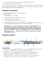
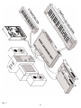
A typical MIDI interface system set-up (see Fig. 1) consists of a MIDISPORT
8x8/s, a host computer, your sequencing software, a tape deck, a master MIDI
keyboard, and additional MIDI sound modules and/or keyboards. This set-up is
connected as follows:
1. The MIDISPORT 8x8/s “USB” jack is connected to the USB port of a host
computer, using the supplied USB cable. The MIDISPORT can also be
connected via its “PC/Mac Host”serial connector and the computer’s serial
port. See installation sections for more information.
2. MIDISPORT 8x8/s MIDI In-8 is connected to MIDI Out of your MIDI master
keyboard.
3. MIDISPORT 8x8/s MIDI Out-8 is connected to MIDI In of your MIDI master
keyboard.
4. The tape deck Tape Out (or Sync Out) is connected to the MIDISPORT 8x8/s
SMPTE In.
5. The tape deck Tape In (or Sync In) is connected to the MIDISPORT 8x8/s
SMPTE Out.
6. A secondary MIDI keyboard (Keyboard 2) MIDI Out is connected to the
MIDISPORT 8x8/s MIDI In 1, with MIDISPORT 8x8 MIDI Out-1 connected to
Keyboard 2’s MIDI In.
7. Additional MIDI Sound Modules (Modules 1 and 2) is directly connected to
the MIDISPORT 8x8/s MIDI Out-2, MIDI Out-3, etc. MIDI In, in this case,
would only be used to transfer sysex information from the sound module to
the computer.
In this example, the MIDISPORT 8x8/s provides several functions: 1) it acts as a
multi-port MIDI interface between the host computer and the connected MIDI
keyboards and sound modules; 2) it synchronizes the host computer to the tape
recorder by converting the tape recorder ‘s SMPTE signal into MIDI Time Code
for use by the host’s MIDI sequencer application; 3) it acts as a SMPTE striper for
writing a SMPTE track to the tape recorder.
25
Fig. 1
26
While connected to the host computer, the MIDISPORT 8x8/s SMPTE write
functions may be controlled by either the front panel pushbuttons or by Remote
Control software running on the host computer. Before connecting each piece of
equipment, it is a good idea to verify that each piece is powered down. After all
connections are made, apply power to each device once again.
NOTE: The MIDISPORT 8x8/s may be left attached to a computer that is turned
off. For USB interface operation, it is advised to power up the unit first.
However, for serial port interface operation the MIDISPORT 8x8/s should
ALWAYS be powered up before the computer. The USB connection may be “hotplugged,” but the serial cable should not be connected or disconnected while
either host or MIDISPORT is powered up.
Using the MIDISPORT in your Application
Software
Once the MIDISPORT driver has been installed, you will need to configure your
MIDI application software to utilize the MIDISPORT. The manner in which this
is done varies between applications, so we will just cover the basics here.
Generally, with both the Mac and PC, most MIDI applications have a MIDI port
configuration or settings dialog box, sometimes called “MIDI Devices” or “MIDI
Setup.” It is within this dialog box that you will select or enable your MIDI input
and output devices. For the Mac, choosing OMS compatibility from this MIDI
Setup page is most often necessary. It is then that you will be able to access the
MIDISPORT’s input and output ports from OMS.
If the MIDISPORT drivers are properly installed, then the MIDI port selections
will be the “MIDISPORT In-1” through “MIDISPORT In 8,” plus “MIDISPORT
Sync/Status” in the input column, and then “MIDISPORT Out-1” through
“MIDISPORT Out-8,” plus “MIDISPORT Control” in the output column. Inputs
1 through 8 correspond to the physical MIDI In connectors 1 through 8, and the
SMPTE/Status corresponds to the 1/4” SMPTE Input connector. Outputs 1
through 8 correspond to the physical MIDI Out connectors 1 through 8, and the
SMPTE Control corresponds to the SMPTE processor command port.
Although the SMPTE/Status driver transfers MIDI Time Code data into the
program, the SMPTE Control driver does not actually transfer SMPTE data out
of the program. Instead, it is used by applications like the Remote Control to
configure and control (Start Writing, Stop Writing, User Bits, SMPTE format, etc.)
the SMPTE processor that resides inside the MIDISPORT 8x8/s. If you wish to
transmit MTC through the MIDISPORT, do it through one of the MIDI output
devices. This, however, will ultimately be up to your music application and its
capacity to send MIDI sync or MIDI timecode while the MIDISPORT is in
Interface mode.
Some MIDI applications may limit the total number of input and output ports
that may be used at one time, but you should have no trouble enabling and
27
using all eight MIDISPORT input ports and the eight output ports in most up-todate programs. The output port that you select on a specific MIDI track within
your sequencer will output MIDI information to the keyboard or sound module
that is attached to that port.
MIDISPORT Remote Control Software
Included with your MIDISPORT 8x8/s is Remote Control software for both
Windows and Macintosh that enables you to configure and control the
MIDISPORT 8x8/s SMPTE functions from your computer. The software enables
you to set user bits, frame format, flywheel and write start time (offset), as well
as start and stop SMPTE writing. Different Remote Control software settings
may be saved to disk as “configurations” and reloaded at a later time.
Additionally, MIDI patchbay configurations can be set from the remote software,
giving you numerous routing possibilities when using the MIDISPORT and your
MIDI keyboards in “Patchbay” mode.
NOTE: The MIDISPORT retains all SMPTE and Patchbay settings in
its internal memory. After changing settings externally (via front
panel format or offset settings, user bits read externally, or even
setting patchbay configurations on another computer), the Remote
Control software will read these settings when launched and
configure itself to reflect the current MIDISPORT settings.
Remote Control Windows Installation
To install the MIDISPORT 8x8/s Remote Control application into Windows,
insert the Midiman MIDISPORT 8x8/s Driver Software CD or diskette into your
disk drive. Next, under the Windows Start menu, select “Run...”. When
prompted to enter a command line, type either D:\8X8MIDISPORT\
REMOTE.EXE if your CD drive letter is D, or A:\8X8MIDSPORT\REMOTE.EXE
if you’re using a diskette in drive A, or whichever drive letter is appropriate for
your CD or floppy disk drive. Next, select the OK button. The SETUP program
will automatically guide you through the installation and create a MIDIMAN
group with a MIDISPORT 8x8/s Remote Control icon.
By default, the Remote Control setup program installs the MIDISPORT Remote
Control to C:\Program Files\Midiman\MIDISPORT8x8-s Remote. You might
want to create a shortcut to it that you can place on your desktop. To do this,
open the Windows Explorer by Start | Programs | Windows Explorer. Under
the C drive list, click on the plus sign next to Program Files, click the plus sign
next to Midiman, and then click the MIDISPORT8x8-s Remote folder. In the list
of Contents (the right column of Explorer), right click on the file named
MSport88 Remote and select “Create Shortcut.” This will create a shortcut file in
the Contents list that you can then click and drag to your desktop.
28
Remote Control Mac Installation
To install the MIDISPORT 8x8/s Remote Control application onto your
Macintosh, first insert the Drivers Software CD or diskette into the appropriate
disk drive. When the disk icon appears, double click on it. Next, locate the file
“MIDISPORT8x8 Remote” within the MIDISPORT8x8 Mac folder (if using a
floppy disk, this folder will be called “MS8x8Mac”), then click on it and drag it
onto your hard drive. Double clicking on the MIDISPORT Remote application
from your hard drive will then open the MIDISPORT 8x8/s Remote Control.
You can create a shortcut by highlighting the remote software file on your hard
drive, then holding the Apple key + M. After doing so, you may drag your new
“alias” to the desktop for easy access.
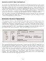
Remote Control Operation
The primary screen of the MIDISPORT Remote Control Software gives you
complete control over all of the SMPTE sync functions of the interface.
MIDISPORT Patchbay configurations are set from within the remote control
software (see “Remote Control Patchbay Operation” section). If you haven’t
worked with SMPTE/MTC sync before, we suggest that you read the section of
the MIDISPORT manual entitled “SMPTE/MIDI Time Code Tutorial.”
The controls are fairly self-explanatory. Format sets the SMPTE frame rate for
the MIDISPORT SMPTE generator. Flywheel sets the number of frames the
reader/regenerator will automatically “time out” on and correct when receiving
either bad or no time code (slide the Flywheel fader towards 0 to set “Jam Sync”
mode). The “Start Writer” button starts and stops the SMPTE writer. The Start
Writer button will change to “Stop Writer” after it has been clicked to begin
writing. The “Start Time” and “User Bits” buttons allow you to set, respectively,
SMPTE start time and the outgoing user bits.
29
NOTE: The MIDISPORT Remote Control software loads with a
preset for each of the SMPTE frame rates. These presets are
appropriately named for the way in which the frame rate is used.
You may use these as they are, or modify them and save them as
desired.
To Set SMPTE Frame Rate
Click the button next to the SMPTE frame rate that you wish to use. The LEDs
on the MIDISPORT front panel to the right of the Format button should reflect
these changes.
To Set Flywheel
Click on the slide fader and drag it until the desired setting is reached. The
number selected represents the number of frames that will be “tolerated” if a
dropout in the SMPTE that is being read has occurred.
To Set SMPTE Start Time
The SMPTE start time defaults to 1 hour. To change the SMPTE start time, click
on the box that contains the start time settings. Highlight the numbers in the
area you wish to change (Hours, Minutes, etc.) and enter the desired start time
values. The “Tab” key will move you to the next field. Click OK when you are
finished selecting the new start time.
To Set User Bits
User Bits are set to all zeros as the default. To change the user bit setting, click
on the User Bits box. Highlight the User Bits area you wish to change (there are
eight bits that can be encoded with information) and enter the desired single
digit. The “Tab” key will move you to the next field. Click on OK when you
have created the desired setting.
Configuration Names
When the Remote Control software loads, it reports the name of the saved or
pre-set configuration that matches the current SMPTE configuration settings.
When a configuration is loaded, the name of the current configuration is shown
in this area.
When a change is made to a configuration, an asterisk appears next to the
current configuration name until the setting is saved. Clicking on the
“Configuration Name:”text or the configuration name will open the “Load
Config” dialog box.
30
Windows Menus
Following are explanations of the program menu choices.
File | Load Config
Retrieve a previously saved SMPTE configuration. Several “factory pre-set”
configurations are included during program installation. You will be given the
opportunity to save or discard any unsaved changes before the configuration you
have selected is loaded.
The Load Configuration dialog contains a "Restore Configuration To Default"
button that may be used to restore a selected factory configuration to it's original
value. When pressed, any changes that you may have made to a factory
configuration will be lost. Be careful. This button has no effect on non-factory
configurations that you may have previously created.
You may also invoke the Load Configuration dialog by clicking anywhere on the
configuration name. You may find this easier than choosing Load Config from the
menu.
File | Save Config
Save the currently active SMPTE configuration. All aspects of the SMPTE
settings (start time, user bits, etc.) are saved with the configuration file. An
asterisk ("*") is placed after the configuration name to indicate when current
settings have not been saved.
File | Delete Config
Delete a SMPTE configuration from the provided list. Factory supplied
configurations can not be deleted (however default values can be restored from
the Load Configuration dialog).
File | Confirm Exit
If this is checked, you will always be asked to confirm that you actually want to
quit the program (a good choice for people who are mildly paranoid about
losing any of their work). On the other hand, if you are irritated by the
confirmation dialog and don’t want to be re-asked each time you choose to exit
the program, uncheck this selection.
File | Always on Top
If this menu item is checked, the Remote Control will remain on top of all other
application windows. This feature is useful if you have other application
windows open and don't want to lose sight of the MIDISport Remote Control.
31
File | Exit
Quit the program. If the Confirm Exit option is checked (see above) the program
will have you confirm that you want to quit before it actually closes.
Hardware | Current Status
This selection gives you the current status of the MIDISPORT MIDI drivers, and
displays whether or not the MIDISPORT hardware is present and detected. The
MIDISPORT internal firmware revision is also displayed here if the MIDISPORT
is present and detected.
Hardware | Patchbay
Selecting “Patchbay” brings up the Patchbay Setup dialog box, enabling the user
to create patchbay configurations that will be remembered by the MIDISPORT.
This patchbay setup can be used only when the MIDISPORT is in standalone
mode. See section, “Remote Control Patchbay Operation” that follows.
Hardware | SMPTE Test
This selection gives you the current status of the SMPTE reader. This pop-up
dialog will tell you whether or not the MIDISPORT is currently locked to SMPTE
and what the incoming SMPTE format is. This feature is very handy if you are
experiencing SMPTE synchronization problems. If unable to lock onto an
incoming SMPTE signal from this dialog box, you should check your SMPTE
connections and SMPTE source.
Help | About
The usual information: what the program is, what software version, who wrote
it, copyright notice, etc.
Macintosh Menus
Following are brief explanations of the remote control program menu choices on
a Macintosh computer.
File | New Setting
When the MIDISPORT Remote Control is first opened, the default setting is
“MIDISPORT Preferences.” Clicking “New Setting” in the file menu will reset
all Remote Control settings to their defaults, while bringing up a new setting
configuration entitled “New Configuration.”
File | Open Setting
If you have saved a configuration setting previously, Open Setting will bring up
a dialog box that will allow you to choose the saved setting. Locate the setting
32
you wish to load (you may want to create a folder to store several saved settings)
highlight it and then open it by clicking “Open.”
File | Close
This option is grayed out while in Remote Control mode. It is accessible when
using the MIDISPORT diagnostics and can be used to close the diagnostics when
you are through. Clicking the square in the left corner of the diagnostic box will
also close it.
File | Save Settings or File | Save As
If you have changed remote Control settings and wish to save them to be
recalled at a later date, open the file menu and click “Save.” This will bring up a
dialog box that asks you to name the file and then click “Save.”
“Save As” should be used to save an existing file under a different name.
Opening the File menu and clicking “Save As” will bring up the same dialog box
that asks you to name the file, then click “Save.”
File | Revert To Saved
If you’ve opened a file and changed settings, yet wish to switch back to the
original file that you had opened, then open the File menu and click “Revert To
Saved.” This will reset the Remote Control to previously saved settings.
File | Save As Default
Opening the File menu and clicking “Save as Default” will take the current file
that is open and its settings and make it the current default settings file.
Opening the MIDISPORT Remote Control in the future will bring up this new
default, still using the name “MIDISPORT Preferences.” Quitting the application
will then ask you if you want to save the changes under a new name. Choosing
to do so will save the settings to another file name. Choosing “Don’t Save” will
still bring up those changed settings as the default “MIDISPORT Preferences.”
File | Quit
Choosing File|Quit will exit the application. A dialog box will appear asking if
you wish to save settings, if changes have been made to the configuration
currently loaded.
Edit | Cut, Copy, and Paste
Cut, Copy, and Paste are accessible from the Edit Menu. These can be used for
offset values or user bit values and will remain in the clipboard while moving
from file to file within the application.
33
Hardware | Current Status
Clicking on “Current Status” will display the OMS version that is in use, plus
the MIDISPORT’s firmware revision number. Clicking “SMPTE Test” will
display the SMPTE time seen at the input as well as the frame rate that is being
detected. This is useful when reading and/or regenerating SMPTE.
The Select Menu
This menu allows the user to select between the Remote Control, the Diagnostic
test, and the Patchbay functions. Running the application opens up the Remote
Control, so clicking on “Diagnostic” from the Select menu will then open the
Diagnostic test. Clicking one or the other from the Select menu will bring that
window to the forefront. See section “Running the Diagnostics.”
Select | Patchbay
Selecting “Patchbay” brings up the Patchbay Setup dialog box, enabling the user
to create a patchbay configuration that will be remembered by the MIDISPORT.
This patchbay setup can be used when the MIDISPORT is in standalone
“Patchbay” mode. See section, “Remote Control Patchbay Operation” that
follows.
Help
The Help menu will allow you to either show or hide “Balloon” help. One can
also select “About Balloon Help” for information about Balloons.
Remote Control Patchbay Operation
The patchbay functions of the MIDISPORT 8x8/s are configured by the Remote
Control Software and saved in the internal memory of the MIDISPORT 8x8/s.
You must be using your MIDISPORT in one of the three interface modes, USB,
serial PC or serial Mac, while writing patchbay settings into memory. Then, you
must exit the interface mode into standalone “Patchbay” mode in order to use
the patchbay settings with your MIDISPORT.
Once you have saved a set of patchbay programs, from one patchbay program
up to a possible eight programs, they are permanently available for use when the
MIDISPORT 8x8/s is in Patchbay mode. You may choose to reconfigure, or
overwrite your patchbay setings at any time.
The MIDISPORT is in Patchbay mode when it is not being used as an interface
and when “Thru” mode or “Cable Test” is not selected from the front panel. The
condition under which your MIDISPORT will function in Patchbay mode is as
follows:
Power up the MIDISPORT while it is completely unattached to the host
computer, or connected to the host computer with the computer powered off.
Then select either USB, PC, or Mac modes using the front panel Mode switch.
34
The mode LED will blink, indicating that the MIDISPORT is in Patchbay mode,
not in Interface mode.
Setting Patchbay Programs
Dropping down the remote control “Hardware” menu and selecting “Patchbay”
will bring up this dialog box. From this screen, you can set up all of your
patchbay programs to be stored inside the MIDISPORT. Just choose a program
number by clicking on the up/down arrows, and then click in the boxes to setup
the signal routing. When you click on “OK,” the program stores that program in
the MIDISPORT. The default settings are all inputs merged to all outputs.
In Patchbay mode, the MIDI inputs are routed to MIDI outputs according to 8
different user programs. A user program specifies the routing/merging between
MIDI inputs and outputs. Any of the 8 MIDI Ins may be routed to any or all of
the 8 MIDI Outs simultaneously. If multiple Ins are assigned to a single Out,
then the MIDISPORT 8x8/s automatically merges the MIDI messages.
The user programs are set up and managed by the provided Remote Control
software. Once the Remote Control software creates the user programs, the
programs are stored internally in the MIDISPORT 8x8/s and will remain intact
even with the power off.
Changing Programs Using Program Change Messages
The MIDISPORT may be switched to the other available programs numbers via
MIDI Program Change messages. The Program Change messages must be
received at MIDI IN8 and on MIDI Channel 16 only. These program changes
only apply to Patchbay mode and not Interface mode.
35
When sending Program Change messages to the MIDISPORT’s IN8, program
numbers 01 through 08 will be accepted and will switch from Patchbay Program
1 through 8 respectively. Above 08, the program numbers wrap-around.
For example, program 09 selects MIDISPORT 8x8/s user program 01, program
10 selects MIDISPORT 8x8/s user program 02, etc.
The MIDISPORT will accept program change messages while in any mode
(except for Cable Test). The patchbay routing setup, however, is only available
when the MIDISPORT is in Patchbay Mode. When the MIDISPORT 8x8/s
powers up for the first time, it configures itself to program number 00 by default.
Once the program number has been changed, the MIDISPORT will always
remain on the last program number in use before the MIDISPORT was powered
down.
Changing Programs Using the Front Panel Reset Switch
The front panel “Reset” switch may also be used to cycle the MIDISPORT
through the eight patchbay program settings that have been configured by the
remote control. The Reset switch will also display the current program number
in use.
1. Press in the Reset button and hold it for two seconds. All of the MIDISPORT
“In” LEDs, except for the number corresponding to the currently selected
patchbay configuration, will light. You may release the Reset button at this time
if you wish to retain the current setting. The remaining seven LEDs will stay lit
for another moment.
2. The MIDI In LED number of the last patchbay configuration used will remain
unlit, indicating that that patchbay program number is the current setting.
3. Continuing to hold in the Reset button will begin to cycle the MIDISPORT
through all eight of its patchbay programs, the unlit LED indicating the current
program number. Releasing the Reset button will set the patchbay program
number to the number of the corresponding MIDI In LED currently unlit.
Diagnostics Software
If you are using the MIDISPORT 8x8/s as a MIDI interface connected to the host
computer ’s serial port, you can ensure reliable connection between the
MIDISPORT and the host computer by running the included diagnostic
software. This diagnostic test will only function with a serial port connection to
the PC or Mac host computer.
PC Diagnostics Application
The included PC Drivers disk contains the MS88DIAG.EXE diagnostic program.
It is intended for testing the MIDISPORT-to-PC connection via the computer’s
36
serial port..
Note: The PC diagnostic program may be run from either the “true”
DOS prompt, or from a DOS box in Windows. It will not operate on
a Mac computer.
To run the program, insert the MIDIMAN Drivers disk into your computer’s
disk drive. If your MIDISPORT came with a floppy disk, follow the instructions
that follow. If your MIDISPORT came with a CD, we suggest copying the
MS88DIAG file from the CD onto a floppy, and then following the instructions
that follow.
Verify you are accessing the proper disk drive by typing either “A: <Enter>” or
“B: <Enter>” at the DOS prompt. This should give you either the A:\> prompt,
or B:\>, depending on which drive letter represents your 3.5” floppy drive.
Once you see this prompt, type “MS88DIAG” and press the <Enter> key.
Once in the diagnostic program, you can press your computer’s <Enter> key to
toggle through the COM Port setting until it matches your setup. As you select
your COM port, the program will automatically setup the standard I/O address
and IRQ for that COM port. This will work for nearly all systems. Occasionally
custom-configured computers will require tweaking of the Address and/or IRQ
settings. To change these, use the <up> and <down> cursor keys to select the
Address and/or IRQ Number, then <Enter> to change that parameter’s setting.
Next, connect a single MIDI cable from MIDISPORT MIDI In-A to MIDI Out-A
(the front two MIDI jacks) of the MIDISPORT 8x8/s. This cable will be used to
“loop back” MIDI data - the MIDISPORT will transmit MIDI data from Out-A
and receive/verify it at In-A.
IMPORTANT: When performing this test be sure that MIDISPORT
MIDI In-1 and MIDI Out-1 are connected properly with a standard
MIDI cable. Otherwise the diagnostics program will indicate that
your unit is failing the test.
Now connect the SMPTE In jack to the SMPTE Out jack using a single standard
male-to-male 1/4” phone cable. This cable will be used to “loop back” and verify
SMPTE data.
Move the cursor down to the “Run Tests” line and press <Enter>. The program
should run through five separate tests. If any of these tests fail, go back and
make sure that you have followed the setup instructions exactly. Once the first
run of tests has passed, toggle the settings on the “Loopback” line of the
diagnostics screen to verify other MIDI input and output ports. Move the
connecting MIDI loopback cable to match the setting on the diagnostic program
screen and re-run the tests to make sure that all of your MIDISPORT inputs and
outputs are working properly.
Mac Diagnostic Application
Included with your MIDISPORT 8x8/s is Remote Control and Diagnostic
37
software that enables you to configure and control your MIDISPORT 8x8/s
SMPTE functions directly from your computer, as well as the diagnostic test for
basic MIDISPORT functionality using the Macintosh serial port connection. The
diagnostic test for Macintosh is contained within the Remote Control software.
To install the MIDISPORT 8x8/s Remote Control & Diagnostic application onto
your Macintosh, first insert the disk entitled “MIDISPORT 8x8/s Drivers
Software” into your disk drive. When the disk icon appears, double click on it.
Next, locate the file “MIDISPORT Remote”, click on it and drag it onto your hard
drive. Double clicking on the MIDISPORT Remote application from your hard
drive will then open the MIDISPORT 8x8/s Remote Control.
Open the Select Menu, then click Diagnostics. This will bring up the
MIDISPORT diagnostic test for Macintosh computers. The Diagnostic test page
will show you the Device Port that the MIDISPORT is connected to, the
“Loopback:” test that will be performed with a dropdown menu to select other
configurations (the default is Out 1 to In 1), plus a “Passes” list that allows you
to select how many times the diagnostic will run (the default is 1 pass).
To perform this test you must create a MIDI “loopback” by taking one MIDI
cable and plugging one end into Input-1, and the other end into Output-1. Also,
a single standard male to male phone cable must be plugged in-between the
SMPTE In and Out on the MIDISPORT’s back panel. Once this has been done,
click the “Run Tests” button. This will perform a series of 5 tests. Refer to these
pages and the troubleshooting guide if your unit fails any of these tests.
To test the functionality of other MIDI ports on the MIDISPORT, pull down the
“Loopback:” menu and select another configuration, e.g. Out 2 to In 2. You will
now need to plug your loopback MIDI cable from Input 2 to Output 2 (in this
case). Once again, click Run Tests.
Test Results for Mac or PC
Below are brief descriptions of each test phase:
1. Internal Hardware Test
This test verifies the MIDISPORT-to-host connection. If the connection is
working properly, the test will display “PASS” and return the MIDISPORT’s
internal firmware revision number. Write this revision number down in case
you ever need to contact Midiman Tech Support.
If your MIDISPORT fails this test, it could mean a bad MIDISPORT or other
hardware failure, but most often it means one of a few very specific things:
• You have selected the incorrect port settings in the diagnostic program.
• MIDISPORT power is not properly connected.
• Your serial cable is not compatible or is defective.
38
• Your computer’s serial port is configured incorrectly, is defective or disabled.
There may be an infrared function available for the serial port, and it is
enabled. You should disable the infrared function via the BIOS CMOS Setup
of your computer’s motherboard
2. Internal Buffers Test
This test verifies the MIDISPORT-to-host connection, as well as the
MIDISPORT’s internal MIDI data buffers. If it fails, it most often is due to one or
more of the following:
• Your serial cable is not compatible or is defective.
• Your computer’s serial port is configured incorrectly, is defective or disabled.
There may be an infrared function available for the serial port, and it is
enabled. You should disable the infrared function via the BIOS CMOS Setup
of your computer’s motherboard
• The MIDISPORT is defective. This is extremely rare as the MIDISPORT units
are tested rigorously at the factory before shipping. If you think this is the
case, please contact MIDIMAN Technical Support.
3. Transmit/Receive Test
This test verifies the MIDISPORT’s ability to transmit and receive MIDI data on
its ports. If it fails, it most often is due to one or more of the following:
• The loopback MIDI cable is incorrectly connected. Check to make sure that
you have a MIDI cable connected between the MIDISPORT MIDI In and the
MIDISPORT MIDI Out selected in the diagnostic program. There should be
no MIDI instruments, mergers, or thru boxes connected to the MIDISPORT
during this test; it is a closed-loop test with one MIDI cable connected
between two MIDI jacks of the BiPort.
• The MIDI cable you are using to loopback data is defective.
• The MIDISPORT is defective. This is extremely rare as the MIDISPORT units
are tested rigorously at the factory before shipping. If you think this is the
case, please contact MIDIMAN Technical Support.
4. Receive Interrupt Test
This test verifies the reception of data from the MIDISPORT under interrupt
(IRQ) control. If this test fails, it is host serial port related. More specifically it is
almost always host IRQ-related.
Most computers use IRQ4 for COM1 and IRQ3 for COM2. If you have the
MIDISPORT connected to COM1 on your computer and have IRQ=4 set in
MS88DIAG.EXE, but it fails the Receive Interrupt Test, you could have an
internal modem connected COM1 or another odd numbered COM port using
39
the same IRQ. Another possibility is a driver associated with another device
used on the same serial port is adversely affecting the IRQ. Yet one more
possibility is that your serial port IRQ is disabled in your computer’s BIOS
CMOS setup, and simply needs to be switched on.
If you are unsure what your port IRQ is or how to find out, please see the section
in this manual titled “Selecting a Host Serial Port,” or consult your computer
owner’s manual or computer manufacturer directly.
5. SMPTE I/O Test
This test makes sure that the SMPTE In and Out jacks are functioning properly.
If this test fails, make sure that the cable you have looped from SMPTE In to
SMPTE Out is good, and also properly connected.
SMPTE/MIDI Time Code Tutorial
This section gives a brief tutorial on various SMPTE topics. This section is not by
any stretch of the imagination an exhaustive treatment of time code or syncing.
Instead, it is included to make the MIDISPORT 8x8/s SMPTE functions more
understandable.
What is SMPTE (Time Code)?
SMPTE is a time coding standard, which was developed in 1967 by the Society of
Motion Picture and Television Engineers (SMPTE) to be used in video editing.
SMPTE attaches a unique time stamp (80 bits of information) to each frame of
video or film. SMPTE readers may then extract that time information and
synchronize other devices to it. Because SMPTE may be encoded as an actual
audio signal, it also lends itself to audio applications and can be read from audio
tracks for synchronization purposes..
The SMPTE Time Code consists simply of: Hours : Minutes : Seconds : Frames.
Therefore a typical SMPTE time code reading would be: 01 : 25 : 42 : 17, which
represents the time 1 hour : 25 minutes : 42 seconds : 17 frames.
The original SMPTE Time Code was Longitudinal Time Code (LTC).
“Longitudinal” means that the code is laid down in a continuous audio stripe
along the length of the tape (longitudinally). The MIDISPORT 8x8/s is designed
to write this longitudinal time code (LTC) as well as read and convert it to MIDI
Time Code (MTC).
What is MIDI Time Code (MTC)?
MIDI Time Code (MTC) is the MIDI implementation of SMPTE. MTC was first
standardized in 1987 as a method of synchronizing MIDI software and hardware
sequencers, as well as drum machines. Later it was also adopted by digital audio
recording software and hardware manufacturers as a method of synchronizing
40
to audio and video gear. Interfaces such as the MIDISPORT 8x8/s perform the
essential task of reading longitudinal SMPTE from an audio and/or video tape
and converting it to MTC for use by MIDI applications.
MTC implements a special System Common MIDI message that is sent four
times per frame (every quarter-frame). Each of these “quarter-frame” messages
is two bytes long and contains one eighth of a complete time code value. A unit
or program receiving MTC must receive eight of these messages in order to
construct the complete time. By the time 8 quarter-frame messages are received
and the complete time is constructed, that time value is two frames old and it
would seem that any synchronized application would always be two frames
behind. Fortunately, most sequencer programs add two frames to the received
MTC in order to derive the current time.
As long as a longitudinal SMPTE source is running, time code may be read.
However, what happens when it stops? The LTC is no longer readable and the
MIDISPORT 8x8/s sends a standard MTC NAK (signal not acquired) message to
the application to indicate the tape has become idle.
About Frame Rates
All SMPTE time code and MTC carries the same primary information,
Hours:Minutes:Seconds:Frames. However, SMPTE time code can be written and
read at different standard frame rates. These frame rates designate the.30
number of frames that each second is subdivided into. Different video, film and
audio standard frame rates have been adopted. These various standards and
typical applications are:
Frame Rate Application
24 frames/second Motion Pictures (film)
25 frames/second European Video - both B/W & Color
30 drop frame U.S. Color Video
29.97 frames/sec. U.S. Color Video
30 non-drop U.S. B/W Video and U.S. Audio
Black and white video frame rates were originally derived from the A/C line
frequency of the indigenous country (e.g. 50 Hz in Europe, 60 Hz in the U.S.). In
the U.S. when color video was introduced, part of the black and white frame
information was used to encode the color information. The result was that the
color frame rate ran at an effectively slower rate of 29.97 frames per second. This
slower rate can be approximated by running at 30 frames per second and
skipping 108 frames per hour in the numbering scheme. This method of
“dropping” 108 frames/hour to slow the effective frame rate was termed “drop
frame.” Hence, the standard frame rate used when doing U.S. color video is
called “30 drop frame.” When running at a t rue 30 frames per second, this is
known as “30” or sometimes “30 non-drop.”
As listed in the above table, in the U.S. and other “NTSC” countries, black and
41
white (30 non-drop) and color (30 drop) video have different frame rates. While
in Europe and all “PAL” countries, black and white and color video have the
same frame rate of 25 frames per second.
What Frame Rate and Settings Should You Use?
The following table summarizes the frame rates that we recommend you use
when striping SMPTE:
Application Frame Rate
Audio Only 30 non-drop
Video - Color U.S. 30 drop*; 29.97
Video - B/W U.S. 30 non-drop
Video - Color Europe 25
Video - B/W Europe 25
** Note: If you are in the U.S. and using a MIDISPORT 8x8/s to do
audio scoring or MIDI sequencing for your own video, then we
suggest you use 30 non-drop instead of 30 drop. This is because
drop-frame is harder to work with, since time calculations are more
complicated. Non-drop will allow you to sync just as well as dropframe; drop-frame is really only a necessity for broadcast
purposes.
SMPTE and MTC User Bits
The SMPTE and MTC standards provide a means for users to “stamp” their
media with reference numbers of their own choosing. This is accomplished by
setting aside some spare data (32 bits) within the time code message to be used
as “User Bits.” SMPTE and MTC allow you to encode these User Bits into the
time code message without affecting the time code itself.
Because there are 32 User Bits available, they can be further subdivided into 8
nibbles (one nibble = 4 bits), each of which can represent a binary-coded decimal
(BCD) digit. A typical set of User Bits might look like this:
04190312
This could be interpreted as April 19, shot 03, take 12. Although this is one
method of encoding user bit information, you may designate the digits in any
way that you desire.
Many inexpensive sync boxes ignore User Bits because they have no way to set
them or read them. The MIDISPORT 8x8/s User Bits can be set via the Remote
Control software and may be displayed with some outboard device such as the
MIDIMAN SMPTE Time Window. The User Bits are also transmitted via MIDI
message to the MIDI application that you are using. If your sequencer is capable
of displaying User Bits information, then you may read the User Bits there as
well.
42
The MIDISPORT 8x8/s is capable of reading and writing SMPTE User Bit
groups U1 through U8. The values of the User Bits output during writing may be
set with the Remote Control software. When reading User Bits from an incoming
source, a MIDI User Bits message is sent to the application each time sync is
acquired and whenever a change in User Bits is detected.
SMPTE Offset
An “offset” is the starting time of the first frame of time code and may be set to
any time value in the range 00:00:00:00 through 23:59:59:29. Usually, you can set
your offset to any value in this range, but sometimes the production
environment will dictate the offset requirements. The MIDISPORT 8x8/s has a
default write offset of 01:00:00:00. If you need to change the offset time, you may
do so via the supplied Windows Remote Control software.
IMPORTANT: Try to avoid high offsets that may wrap around (from 23:59:59:29
back to 00:00:00:00). Some programs become confused by this wrap-around.
Choose an offset that will allow your entire session to be striped without rolling
over the 24:00:00:00 time code value.
At times, you may be given a tape with SMPTE already on it. The offset time on
the tape you receive will affect the start time that you set for your MIDI
sequencing. For example, if the time code on the tape starts at 02:00:00:00 (a 2hour offset) and you need to start your sequence playing 3 minutes, 30 seconds
into the work, you should set the sequencer start time to 02:03:30:00.
Because MTC requires 8 quarter-frame messages to send a full frame of time
code, a minimum of 2 to 4 frames will be needed for a sequencer to first sync up
to a running SMPTE. Therefore, when syncing a MIDI sequencer or any program
to time code, it is a good idea to set your sequence start time to a few seconds
later than the offset of the time code on tape. In other words, give your
sequencer some time to acquire sync and stabilize before it begins playing back.
For example, if your tape starting offset is 01:00:00:00, then set the sequence start
time to 01:00:05:00, which is 5 seconds later. This is also known as a 5-second
pre-roll. Some sequencers will actually allow you to directly set the “pre-roll”
time to a specific number of seconds. These programs will automatically sync up
to an incoming MTC source for that pre-roll amount, and then start playing.
Flywheeling
Due to the nature of magnetic tape, sometimes drop-outs occur on the tape and
leave gaps in the recorded time code. When a drop-out or other media
corruption occurs at the sync source and there is a resulting period of corrupted
time code, the MIDISPORT 8x8/s continues to “flywheel,” outputting time code
from the last properly received frame and incrementing at the proper frame rate.
This flywheeling continues until valid time code reappears on the MIDISPORT
8x8/s SMPTE input or until a preset time-out occurs. The length of this time-out
period is called the “Flywheel Time.” The MIDISPORT 8x8/s flywheel time may
43
be set to any amount from 1 to 255 frames, or infinite. It is good practice to use
the shortest Flywheel setting that will work with the amount of drop-out found
on the media you are syncing to. Infinite flywheeling is also known as Jam Sync
and may be used to continue generating time code long after the time code
source has expired.
Recording a SMPTE Stripe (Writing SMPTE)
Before the MIDISPORT 8x8/s can be used to synchronize to a source audio
and/or video tape, that tape must be encoded with SMPTE time code.
Sometimes you will be provided with a piece of source material that already has
SMPTE on it. In that case, you are not required to record another SMPTE stripe
and may instead read the SMPTE as is. If, on the other hand, your source
material has no current time code encoded you will need to record your own
SMPTE time code to one of the tape’s tracks. This is commonly known as
“striping the tape.” To record a SMPTE stripe onto tape, follow these steps:
1. Use the Remote Control software to set the MIDISPORT 8x8/s frame rate to
the appropriate SMPTE format, as discussed in the About Frame Rates section of
this manual. We recommend you select 30 non-drop for audio, 25 for European
(PAL) video, and, unless you are scoring for commercial release, 30 non-drop for
U.S. (NTSC) video.
2. From the Remote Control software, set the SMPTE offset time to the desired
value. SMPTE offset is displayed on a large button and pressing this button will
allow you to adjust the offset. If no special offset is required we recommend you
use 01:00:00:00 (one hour). Some users want their audio to start exactly on an
even hour boundary -- if that’s your desire, set the offset to something like
00:59:55:00 which will allow 5 seconds of pre-roll before your sequence starts at
01:00:00:00.
3. Optionally, you may now set the “User Bits.” User Bits are not a mandatory
requirement and if you don’t need to set them, the MIDISPORT 8x8/s will
default to standard User Bit settings. User Bits are displayed on the large button
to the right of the offset button and pressing this button will allow you to adjust
the bits.
4. On your tape or video deck, choose the audio channel you will be striping to.
Make sure that the MIDISPORT 8x8/s SMPTE Out is securely connected to the
proper Tape In or Sync In of your tape deck. When choosing an audio channel on
a multichannel deck, pick one of the end channels (e.g. Channel 8 of an 8-track
machine). This will minimize cross talk between the time code and the other
audio tracks of the tape.
5. Put your tape deck into record/pause mode. If you have a deck with a
varispeed adjustment, make sure it is zeroed.
6. Click on the “Start Writer” Button in the Remote Control software. The
MIDISPORT will start outputting SMPTE time code.
44
7. Adjust your recording level to between -10 and -5 dB. You want enough gain
to make a good clean recording, but if the recording is too “hot,” time code noise
may bleed over to other tracks. Also, make sure noise reduction such as DBX or
Dolby is defeated. When writing or reading SMPTE, the data may be corrupted
by noise reduction and the results may be unacceptable. We recommend that
you do NOT use noise reduction when recording or playing a SMPTE sync track.
8. Click on “Stop Writer” to stop the SMPTE code. You are now set to begin
recording the SMPTE stripe.
9. Take the tape deck out of pause. Allow the tape to pre-roll for at least 10
seconds. This pre-roll gives the tape transport time to stabilize and get past the
most dropout-prone area of the tape, the beginning. Click on the “Start Writer”
button to start generating time code.
10. Continue recording several minutes of SMPTE stripe. Naturally, you will
need a stripe that is longer than the piece you are going to sync. It is safer to
record a stripe that is too long than too short -- you can always record over the
end of a long stripe.
11. When done recording the stripe, click on the Remote Control software’s “Stop
Writer” button to stop generating time code.
12. Take your tape recorder out of record.
13. Rewind your tape to just before where you started recording the sync stripe.
That’s it - that’s all there is to recording a SMPTE stripe. You now have a SMPTE
stripe to sync to.
Syncing to a SMPTE Stripe
With a SMPTE stripe recorded on one track of your tape deck, you are now
ready to sync to tape. Set your sequencer to SMPTE/MTC clock, making it a
slave to the MIDISPORT 8x8/s. Since the MIDISPORT 8x8/s auto-detects the
frame rate of incoming SMPTE, it is not necessary to set the frame rate of the
MIDISPORT when syncing. However, you may need to set your sequencer
program to the proper incoming SMPTE format.
Note: The MIDISPORT 8x8/s always stores its current configuration
when you exit Windows. Therefore, when you restart Windows, the
MIDISPORT 8x8/s recalls its last setup and you do not have to
modify it unless you want to change parameters such as frame
format or User Bits. Make sure the MIDISPORT 8x8/s SMPTE In is
connected firmly to the Tape/Sync output of your tape deck.
From your sequencer, you should select the MIDISPORT 8x8/s SMPTE Input as
one of your input devices. Some sequencers will automatically detect MTC
streaming in from this port and sync to it. Others, such as Master Tracks, require
you to designate which input port MTC is coming in on. If this is the case, make
45
sure that you designate “MIDISPORT 8x8/s SMPTE In” as your sync input.
In all sequencers you must set a SMPTE start time at which the sequence will
start playing. This sequencer start time, if not dictated by post production
requirements, should be set to a value at least a few seconds greater than the
SMPTE offset you used to stripe your tape with. For example, if your recorded
SMPTE stripe started at 1 hour you should use a sequencer start time of at least 1
hour and 5 seconds. This small additional time (pre-roll) gives your sequencer a
couple of seconds to lock to SMPTE and stabilize before it has to start playing.
If all of this is done correctly, and you start playing your tape, your sequencer
should start playing exactly at the set sequencer start time. Your sequencer
should stay in perfect sync with the tape, even if you have a varispeed deck. If
you fast-forward and then start playing your tape your sequencer should “chase
lock” exactly to the SMPTE on the tape.
Trouble-Shooting
If you are having problems using your MIDISPORT8x8/s, it is probably a good
idea to re-read this manual and make sure you have properly installed the
interface. If you can’t find the source of your difficulty then check the following
typical fixes:
Interface Trouble-Shooting
SYMPTOM: My computer can’t find the interface when I run my sequencer
program.
SOLUTION 1: You don’t have the driver properly installed, or the driver is not
installed at all. Turn back a couple of pages and follow the instructions for
Software Driver Installation.
SOLUTION 2: The MIDISPORT is not set to the proper mode. Make sure it is
set to "USB" for PC or MAC USB operation, "PC" for PC legacy serial operation,
or "MAC" for Apple serial operation.
SOLUTION 3: The sequencer program is not set up to use the MIDISPORT
driver. This must be done from within the program itself. Make sure the
MIDISPORT8x8/s input and output devices are selected for use by your
sequencer program.
SYMPTOM: The unit works fine with some of my programs but doesn’t work
with others.
SOLUTION: There is probably a set-up problem with the program that isn’t
working. It is likely that you haven’t selected the MIDISPORT driver from
within your application.
SYMPTOM: The MIDISPORT8x8/s driver is properly installed but I’m not
getting any sound when I run my sequencer.
SOLUTION 1: Your application must select the MIDISPORT8x8/s as its MIDI
Input and Output device. This is done from within the application itself.
SOLUTION 2: The MIDISPORT does not produce sound. Instead it connects
46
to external MIDI devices that do produce sound, like a MIDI synthesizer. Make
sure that external MIDI device is properly set up and connected to the
MIDISPORT.
SOLUTION 3: The driver may be disabled. Go to Settings | Control Panel |
System | Device Manager, then open up the list under “Sound, video and game
controllers” by clicking on the “+” sign. Highlight the MIDISPORT, click
Properties, and then uncheck “Disable in this hardware profile.” If using the
serial port drivers, click the Driver Settings tab to view the settings that you have
selected. If the COM port is set to “Disable,” then select the proper COM port.
SYMPTOM: My keyboard shows “MIDI Data Error,” or “MIDI Buffer Full”.
SOLUTION: Check your MIDI cables and MIDI connections. Be sure the cables
are plugged in all the way. If the problem persists try new cables.
SYMPTOM: MIDI is being sent and received properly but when I play my
sequencer it lags and bogs down.
SOLUTION: Make sure you don’t have a MIDI feedback loop. Try turning the
“Local Control” on your keyboard to OFF if it is being used both as a controller
and as a sound module. A MIDI feedback loop can also occur if the MIDI Out of
the interface is somehow connected back to the MIDI In through some external
device. This can be avoided by turning off the MIDI Thru on either your
keyboard or in the application software.
Serial Port Trouble-Shooting
SYMPTOM: The diagnostic program’s Internal Hardware Test reports “FAIL
— Interface Not Found.”
SOLUTION 1: The MIDISPORT is not set to the proper mode.
SOLUTION 2: The Serial Port, IRQ and/or Address settings in the diagnostic
program probably do not match the actual IRQ and Address setting of your
serial port. Set them to the correct value(s).
SOLUTION 3: Make sure the MIDISPORT is properly connected to your
computer, and to the proper COM/Serial port. If your PC COM port is
conflicting with your modem, try the other COM port. For Macs, the modem
port is more desirable than the printer port.
SYMPTOM: The diagnostic program’s Transmit/Receive Test fails.
SOLUTION: Either you forgot to install the MIDI loopback cable, or the ports
you’ve physically looped-back have not been properly specified in the
diagnostic program. This test transmits MIDI data out one port and then verifies
that it can be properly read into another.
SYMPTOM: The diagnostic program’s SMPTE I/O Test fails.
SOLUTION: You may have forgotten to connect the board’s SMPTE In
connector to the SMPTE Out connector using a 1/4” phone cable. This test uses
the cable to write SMPTE back into the unit and verify that it can be properly
read.
47
SYMPTOM: The diagnostic program passes all tests except for the “Receive
Interrupt” test.
SOLUTION: The IRQ setting in the diagnostic program probably does not
match the IRQ setting of your serial port. Make sure they are set to the same
value. If this does not alleviate the problem then your port is probably using
another IRQ than you think it is, or you have another peripheral using the same
IRQ (See the Installation and Diagnostics sections).
Syncing Trouble-Shooting
If you are having trouble syncing to SMPTE you should check the following:
Are you using a high quality tape deck and tape? Have you tried using a higher
quality tape?
Do you have the MIDISPORT8x8/s SMPTE In connected to the proper Tape
Out/Sync Out port of your deck?
Are your SMPTE audio cables good?
Have you discovered the best Input and Output level settings on your tape
deck? You may need to spend some time playing with different playback and
record levels to find the best and most reliable settings. If the signal is too hot or
too low during record or playback you may encounter problems. You should
play with the record and playback levels until you get reliable sync. We have
found that a level of around -10 dB is best.
A SMPTE stripe is essentially data recorded to tape. If your recorder uses noise
reduction, such as DBX or Dolby, when writing or reading SMPTE, the data may
be corrupted and the results may be unacceptable. We recommend that you do
NOT use noise reduction when recording or playing a SMPTE sync track.
If you are recording any kind of a sync stripe and going through a mixing board
to set levels, make sure any EQ is off or flat. If you EQ a SMPTE signal it may
turn to mush. Also, try to avoid the bussing system by using direct outputs.
Are you trying to use SMPTE mode with a sequencer that does not support MTC
or is not set to chase to MIDI Time Code?
With all sequencers you must set a SMPTE song/sequence start time. Make sure
you set this SMPTE start time to a value at least a couple seconds later than what
your SMPTE stripe starts at. For example, if you recorded a SMPTE stripe
starting at 1 hour (01:00:00:00), you should set your sequencer start time to
something like 1 hour and 5 seconds (01:00:05:00).
Make sure your sequencer is set to receive MTC on the Windows driver that has
MIDI Time Code coming over it. This driver is called “MIDISPORT8x8/s
Sync/Status”.
48
If the SMPTE can be heard on neighboring tracks (i.e. there is cross-talk), then try
striping the tape at a lower level. The MIDISPORT8x8/s SMPTE waveform is
specially designed to limit cross-talk (per the SMPTE specification). However, if
it is recorded “too hot”, the signal could bleed into other tracks just as any other
audio signal could.
Before Calling Tech Support
It is best to be in front of the computer in which you are installing the
MIDISPORT 8x8/s when attempting to reach Midiman Technical Support for
help.
Have the computer powered up, with the MIDISPORT 8x8/s Driver Disk and
this manual close by.
Please be ready to identify which Midiman product you have, and to concisely
explain what the problem is that you are encountering.
Take a deep breath, then dial the Tech Support number listed on the back of the
manual or email at the address listed.
Tech Support hours are 9AM to 5PM Pacific time, Monday thru Friday. There is
no best time to call, but persevere and you will get through to a human being
who will be eager to help you.
Expect email answers within 24 to 36 hours.
49
Limited Lifetime Warranty
MIDIMAN warrants that this product is free of defects in materials and workmanship
under normal use so long as the product is: owned by the original purchaser; the original
purchaser has proof of purchase from an authorized MIDIMAN dealer; and the purchaser
has registered his/her ownership of the product by sending in the completed warranty
card.
This warranty explicitly excludes power supplies and included cables which may become
defective as a result of normal wear and tear.
In the event that MIDIMAN receives written notice of defects in materials or
workmanship from such an original purchaser, MIDIMAN will either replace the product,
repair the product, or refund the purchase price at its option. In the event any repair is
required, shipment to and from MIDIMAN and a nominal handling charge shall be born
by the purchaser. In the event that repair is required, a Return Authorization number
must be obtained from MIDIMAN. After this number is obtained, the unit should be
shipped back to MIDIMAN in a protective package with a description of the problem and
the Return Authorization clearly written on the package.
In the event that MIDIMAN determines that the product requires repair because of user
misuse or regular wear, it will assess a fair repair or replacement fee. The customer will
have the option to pay this fee and have the unit repaired and returned, or not pay this
fee and have the unit returned unrepaired.
The remedy for breach of this limited warranty shall not include any other damages.
MIDIMAN will not be liable for consequential, special, indirect, or similar damages or
claims including loss of profit or any other commercial damage, even if its agents have
been advised of the possibility of such damages, and in no event will MIDIMAN’s
liability for any damages to the purchaser or any other person exceed the price paid for
the product, regardless of any form of the claim. MIDIMAN specifically disclaims all
other warranties, expressed or implied. Specifically, MIDIMAN makes no warranty that
the product is fit for any particular purpose.
This warranty shall be construed, interpreted, and governed by the laws of the state of
California. If any provision of this warranty is found void, invalid or unenforceable, it
will not affect the validity of the balance of the warranty, which shall remain valid and
enforceable according to its terms. In the event any remedy hereunder is determined to
have failed of its essential purpose, all limitations of liability and exclusion of damages set
forth herein shall remain in full force and effect.
50
51
52