1
®
4a
t r a n s
•
n a
4-C HANNEL A MPLIFIER
I NSTALLATION & O PERATION
M ANUAL
®
®
Dear Customer,
Congratulations on your purchase of the world's finest brand of car audio
amplifiers. At Rockford Fosgate we are committed to musical reproduction at its
best, and we are pleased you chose our product. Through years of engineering
expertise, hand craftsmanship and critical testing procedures, we have created a
wide range of products that reproduce music with all the clarity and richness you
deserve.
For maximum performance we recommend you have your new Rockford Fosgate
product installed by an Authorized Rockford Fosgate Dealer, as we provide
specialized training through Rockford Technical Training Institute (RTTI). Please
read your warranty and retain your receipt and original carton for possible future
use.
To add the finishing touch to your new Rockford Fosgate image order your Rockford
accessories, which include everything from T-shirts and jackets to hats and
sunglasses.
To get a free brochure on Rockford Fosgate products and Rockford accessories, in
the U.S. call 602-967-3565 or FAX 602-967-8132. For all other countries, call
+001-602-967-3565 or FAX +001-602-967-8132.
PRACTICE SAFE SOUND™
CONTINUOUS EXPOSURE TO SOUND PRESSURE LEVELS
OVER 100dB MAY CAUSE PERMANENT HEARING LOSS. HIGH
POWERED AUTO SOUND SYSTEMS MAY PRODUCE SOUND
PRESSURE LEVELS WELL OVER 130dB. USE COMMON SENSE
AND PRACTICE SAFE SOUND.
If, after reading your manual, you still have questions regarding this
product, we recommend that you see your Rockford Fosgate dealer. If you
need further assistance, you can call us direct at 1-800-795-2385. Be sure to
have your serial number, model number and date of purchase available
when you call.
The serial number can be found on the outside of the box. Please record it
in the space provided below as your permanent record. This will serve as
verification of your factory warranty and may become useful in recovering
your amplifier if it is ever stolen.
Serial Number: ____________________
Model Number: ____________________
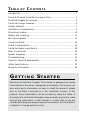
TABLE
OF
CONTENTS
Introduction ...................................................................................... 1
Punch 4-Channel Amplifier Accessory Pack ...................................... 1
Rockford Fosgate Accessories ............................................................ 2
Technical Design Features ................................................................ 3
Design Features ................................................................................. 7
Installation Considerations ................................................................ 9
Mounting Location .......................................................................... 10
Battery and Charging ....................................................................... 11
Wiring the System ........................................................................... 11
Using the XCard .............................................................................. 14
XCard Configurations ...................................................................... 15
Using the Signal Input Switch .......................................................... 18
Basic Connections ........................................................................... 20
System Diagrams ............................................................................. 27
Troubleshooting .............................................................................. 31
Dynamic Power Measurements ....................................................... 34
400x4 Specifications ....................................................................... 37
Warranty Information ...................................................................... 38
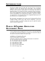
G E T T I N G S TA R T E D
Welcome to Rockford Fosgate! This manual is designed to provide
information for the owner, salesperson and installer. For those of you
who want quick information on how to install this product, please
turn to the Basic Connections in the Installation section of this
manual. Other information can be located by using the Table of
Contents. We, at Rockford Fosgate, have worked very hard to make
sure all the information in this manual is current. But, as we are
constantly finding new ways to improve our product, this information
is subject to change without notice.
INTRODUCTION
The Punch 400x4 (pronounced “x4” not “by 4”) is a 4-channel
amplifier which can deliver 400 watts RMS. This amplifier
utilizes a 2/4-channel input switch to eliminate the need for
signal splitters. Four internal XCard crossovers allow the amplifier to be configured for use with many popular system designs
without the added cost of external processors. The Punch 400x4
is a powerful 4-channel amplifier with integrated features which
are offered at a competitive price.
We strongly recommend you have your Authorized Rockford
Fosgate Dealer install your new Punch amplifier. If you do
choose to install it yourself, please be sure to read the entire
manual before beginning.
P U N C H 4-CHANNEL A M P L I F I E R
ACCESSORY PACK
The accessory pack shipped with the Punch 4-channel amplifier
includes the mounting hardware necessary to secure the amp to
the vehicle as well as attach the end caps.
Installation & Operation Manual
Punch Verification Certificate
(10) Allen Head Screws for speaker and power connectors
(4) Mounting Screws for end caps
(4) Mounting Screws for amplifier
(1) Allen Wrench 7/64"
(1) Allen Wrench 3/32"
(1) AGU In-line Fuseholder
(1) AGU 50 Amp Fuse
–1–
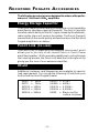
R O C K F O R D F O S G AT E A C C E S S O R I E S
The following accessories were designed to enhance the performance of the Punch 400x4 amplifiers.
Energy Storage Capacitor
The Punch capacitors are used to provide extra current needed by
amplifiers to reproduce musical transients. The Punch Caps also
have the natural ability to filter AC ripple caused by the alternator,
reducing the chance of noise in the system. The Punch Caps will
maximize both the sound quality and performance that Rockford
Fosgate amplifiers can deliver.
Punch Link (FG-LINK)
The Punch Link is a specially cast heatsink interconnect which
allows you to join any of our current Punch or Punch Power
amplifiers together. While providing additional cooling through
the coupling process, the Punch Link adds the finishing touch by
giving you the look of one awesome amplifier.
XCard
Additional crossover card frequencies are available for specialized requirements. You can get the following XCards from your
Authorized Rockford Fosgate Dealer.
XM50
XM70
XM100
XM150
XM200
= 50Hz
= 70Hz
= 100Hz
= 150Hz
= 200Hz
XM275
XM400
XM4.5k
XM6.5k
XM00
–2–
=
=
=
=
=
275Hz
400Hz
4,500Hz
6,500Hz
Blank card for
custom crossover
T ECHNICAL D ESIGN F EATURES
◆ TRANS•ANA (TRANSconductance Active
Nodal Amplifier)
The TRANS•ANA (TRANSconductance Active Nodal Amplifier)
is a circuit that allows the audio signal to pass through the
amplifier at low voltage. The signal is directly level-shifted to the
fixed high voltage rails via a pair of driver transistors. Signal
linearity is assured by an active node formed by the driver
transistors at ultrasonic frequencies. This allows amplifier performance similar to trans•nova which is highly stable and linear
while utilizing the advantages of a non-floating power supply.
THE RESULT: An extended frequency bandwidth accurately
supplied to the output stages of the amplifier.
◆ TOPAZ (Tracking Operation Pre-Amplifier Zone)
The TOPAZ (Tracking Operation Pre-Amplifier Zone) circuitry
solves ground loop noise problems common to automotive
amplifier design. This innovative new development allows vastly
improved isolation of the input signal grounds from the power
supply ground of the amplifier. This is accomplished by allowing
the source unit to control the potential “environment” of the
entire input structure or “zone” of the amplifier. This process
improves the noise rejection of the amplifier by 30-40dB – an
astounding 30-100 times better than amplifiers without TOPAZ.
THE RESULT: Elimination of troublesome ground loop noise
between source and amplifier.
–3–
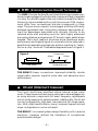
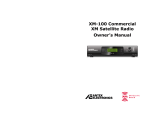
◆ DSM (Discrete Surface Mount) Technology
The DSM (Discrete Surface Mount) manufacturing process combines the advantages of both discrete components and integrated
circuitry. Rockford Fosgate is the only American amplifier manufacturer to have invested millions into this process. DSM components differ from conventional discrete components in three
ways. They are more compact, more rugged, and they efficiently
dissipate generated heat. Using them wherever appropriate allows the advantages associated with discrete circuitry to be
retained while also providing room for both highly advanced
processing features and generous PC board copper paths where
needed. Their short lead-out structures allow maximum audio
performance and highest signal-to-noise ratios to be obtained in
amplifiers of desirable package size without resorting to “amplifier-on-a-chip” shortcuts. These advantages are shown in Figure 1.
Figure 1
Component
Solder
Solder
Surface Mount
Thru-Hole
THE RESULT: Fewer connections, improved reliability, shorter
signal paths, superior signal-to-noise ratio and awesome sonic
performance.
◆ XCard (Internal Crossover)
The Punch and Power amplifiers utilize internal active crossovers. These crossovers have many performance advantages such
as using discrete components for exact frequency adjustments
which are far superior to potentiometers. Additionally, the XCard
can be configured for high-pass, low-pass and full range operation. With slight modifications, many crossover frequencies and
slope configurations can be achieved.
THE RESULT: Increased system design flexibility with a precise
electronic crossover without the limitations of conventional
potentiometer designs.
–4–
◆ RTP (Real Time Protection)
NOMAD (NOn-Multiplying Advanced Decision)
The Punch and Power amplifiers use an analog computer process to
maximize safe output power under all operating conditions. Rockford Fosgate pioneered and developed RTP (Real Time Protection),
a crucial element in the performance edge of our amplifiers. The
innovative NOMAD (NOn-Multiplying Advanced Decision) system
is the most sophisticated version of this technique ever used,
bringing previously unavailable levels of accuracy, stability, temperature immunity and reliability to this critical process. NOMAD
makes advanced decisions based on device voltages to precisely
control the awesome levels of current available in the output
MOSFETs to safe values – but only when absolutely needed.
THE RESULT: Extremely fast protection system that always protects
the amplifier and never degrades the sound.
◆ MOSFET Devices
Rockford Fosgate is one of the few manufacturers in the audio
industry to utilize MOSFET devices in both the power supply and
the output stages. MOSFET (Metal Oxide Semiconductor Field
Effect Transistor) devices offer several important inherent advantages over the 30 year old technology of bi-polar design. These
advantages include: thermal stability, switching speed, ultra low
output impedance and wider bandwidth linearity. In addition,
MOSFETs operate very similar to vacuum tubes in which they are
more linear than bipolar transistors. However, MOSFETs can
deliver the midrange clarity without the limitations of transient
response and high frequency phase shifting normally associated
with tube operation.
THE RESULT: Operational characteristics similar to vacuum
tubes without the performance limitations of tube designs.
–5–
◆ Pass-Thru Output
The Pass-Thru output provides a convenient source for daisychaining an additional amplifier without the need for extra RCA
cables or “Y” adapters. The Pass-Thru signal is derived from
summing the Front and Rear Left inputs to create a Left output, and
summing the Front and Rear Right inputs to create a Right output.
When the amplifier is used with 4-channel inputs, the Pass-Thru
provides constant output regardless of the source unit fade
position. Additionally, the Pass-Thru has an XCard that can be set
for High-Pass, Low-Pass or Full Range.
THE RESULT: Constant non-faded output for adding woofer
amplifiers.
–6–
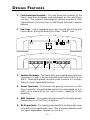
D ESIGN F EATURES
1. Cast Aluminum Heatsink – The cast aluminum heatsink of the
Punch amplifier dissipates heat generated by the amplifier's
circuitry. The inherent advantage of casting provides a 30%
improvement of cooling over conventional extrusion heatsink
designs.
2. End Caps – Interchangeable end caps conceal the wiring and
input cables, giving the amplifier a clean “stealth” look.
8
9
10
7
9
6
3
5
4
11
3
3. Speaker Terminals – The heavy duty, gold-plated terminal block
connectors (+ and –) will accept wire sizes from 8 AWG to 18
AWG. These gold-plated connectors are immune to corrosion
that can cause signal deterioration.
4. Power Terminals – The power and ground connectors on the
Punch amplifier are gold-plated and will accommodate up to 8
AWG wire maximizing the input current capability of the
amplifier.
5. REM Terminal – This spade terminal is used for the auto power/
remote turn-on of the Punch amplifier.
6. RCA Input Jacks – The industry standard RCA jacks provide easy
connections for signal level input. They are gold-plated to resist
the signal degradation caused by corrosion.
–7–
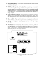
7. Signal Input Switch – This switch allows selection of 2-channel
or 4-channel input.
8. RCA Pass-Thru Jacks – The Pass-Thru provides a convenient
source for daisy-chaining an additional amplifier without running
an extra set of RCA cables from the front of the vehicle to the rear
amplifier location. One of the internal XCards can be designated
to the Pass-Thru, creating a dedicated low-pass, high-pass, or full
range output.
9. Input Sensitivity Controls – The input level controls are preset for
500mV which will match the output of most source units. They
can be adjusted to match input levels ranging from 150mV to 3V.
10. Phase Switch – This switch enables you to easily invert the rear
channel phase without having to disconnect the speaker wires.
11. LED Power Indicator – The LED illuminates when the unit is
turned on.
12. XCard (Internal Crossover) – These built-in crossover cards are
configurable for a multitude of operating frequencies. The orientation of the card in its socket determines the function of highpass, low-pass, or full range operation.
®
®
t
r
a
n
4
s
•
AMPLIFIER
a
n
a
50 Watts x 4 into 4 Ohms with less than 0.05% THD
100 Watts x 4 into 2 Ohms with less than 0.10% THD
®
LP
➝
Low-Pass
FULL ↕
LP
XCard 1
XCard 2
12
XCard 3
XCard Front
XCard Rear 1
XCard Rear 2
Pass-Thru XCard
Full Range
➝
Rear XCards
Dual Filter
➝
Front XCard
HP
➝
High-Pass
HP
ROCKFORD CORPORATION
MADE IN THE USA
XCard 4
XCard Pass-Thru
–8–
I N S TA L L AT I O N C O N S I D E R AT I O N S
The following is a list of tools you will need for installing the Punch
amplifier:
Allen wrenches 7/64" & 3/32" (included)
Wire strippers
Electric hand drill w/assorted bits
Wire crimpers
Voltmeter
Battery post wrench
Wire cutters
Assorted connectors
This section focuses on some of the vehicle considerations for
installing your new Punch amplifier. Checking your battery and
present sound system, as well as pre-planning your system layout and
best wiring routes will save installation time. When deciding how to
lay out your new system, be sure that each component will be easily
accessible for making adjustments.
Before beginning any installation, be sure to follow these simple rules:
1. Be sure to carefully read and understand the instructions before
attempting to install the amplifier.
2. For safety, disconnect the negative lead from the battery prior to
beginning the installation.
3. For easier assembly, we suggest you run all wires prior to
mounting your amplifier in place.
4. Route all of the RCA cables close together and away from any
high current wires.
5. Use high quality connectors for a reliable installation and to
minimize signal or power loss.
6. Think before you drill! Be careful not to cut or drill into gas tanks,
fuel lines, brake or hydraulic lines, vacuum lines or electrical
wiring when working on any vehicle.
7. Never run wires underneath the vehicle. Running the wires
inside the vehicle provides the best protection.
8. Avoid running wires over or through sharp edges. Use rubber or
plastic grommets to protect any wires routed through metal,
especially the firewall.
9. ALWAYS protect the battery and electrical system from damage
with proper fusing. Install the appropriate fuseholder and fuse on
the +12V power wire within 18” (45.7 cm) of the battery terminal.
10. When grounding to the chassis of the vehicle, scrape all paint
from the metal to ensure a good, clean ground connection.
Grounding connections should be as short as possible and always
be connected to metal that is welded to the main body, or chassis,
of the vehicle.
–9–
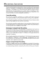
M OUNTING L OCATION
The mounting location and position of your amplifier will have a great
effect on its ability to dissipate the heat generated during normal
operation. The design of our cast aluminum heatsink serves to easily
dissipate the heat generated over a wide range of operating conditions. However, to maximize the performance of your amplifier, care
should be taken to ensure adequate ventilation.
Trunk Mounting
Mounting the amplifier vertically on a surface with the fin grooves
running up and down will provide the best cooling of the amplifier.
Mounting the amplifier on the floor of the trunk will work but provides
less cooling capability than vertical mounting.
Mounting the amplifier upside down to the rear deck of the trunk will
not provide proper cooling and will severely affect the performance
of the amplifier and is not recommended.
Passenger Compartment Mounting
Mounting the amplifier in the passenger compartment will work as
long as you provide a sufficient amount of air for the amplifier to cool
itself. If you are going to mount the amplifier under the seat of the
vehicle, you must have at least 1" (2.54cm) of air gap around the
amplifier's heatsink.
Mounting the amplifier with less than 1" (2.54cm) of air gap around
the amplifier's heatsink in the passenger compartment will not
provide proper cooling and will severely affect the performance of the
amplifier and is not recommended.
Engine Compartment Mounting
Rockford Fosgate amplifiers should never be mounted in the engine
compartment. Not only will this void your warranty but could create
an embarrassing situation caused by the ridicule from your friends.
– 10 –
B ATTERY
AND
C HARGING
Amplifiers will put an increased load on the vehicle's battery and
charging system. We recommend checking your alternator and
battery condition to ensure that the electrical system has enough
capacity to handle the increased load of your stereo system. Stock
electrical systems which are in good condition should be able to
handle the extra load of any Rockford amplifier without problems,
although battery and alternator life can be reduced slightly. To
maximize the performance of your Rockford Fosgate amplifier, we
suggest the use of a heavy duty battery, high output alternator and an
energy storage capacitor.
WIRING
THE
SYSTEM
CAUTION: Avoid running power wires near the low level input
cables, antenna, power leads, sensitive equipment or harnesses. The
power wires carry substantial current and could induce noise into the
audio system.
• For safety, disconnect the negative lead from the battery prior to
beginning the installation.
1. Plan the wire routing. Take care when running signal level RCA
cables to keep them close together but isolated from the amplifier's
power cables and any high power auto accessories, especially
electric motors. This is done to prevent coupling the noise from
radiated electrical fields into the audio signal. When feeding the
wires through the firewall or any metal barrier, protect them with
plastic or rubber grommets to prevent short circuits. Leave the
wires long at this point to adjust for a precise fit at a later time.
2. Prepare the Power cable for attachment to the amplifier by
stripping 5/8" of insulation from the end of the wire. The use of 8
gauge power cable can interfere with the installation of the end
caps. Proper wire dress can prevent this from occurring. To
prevent the wire from fraying, strip the insulation at a 45° angle.
Insert the bared wire into the B+ terminal with the long side of the
insulation on the top. Bend the cable down at a 90° angle. Tighten
the set screw to secure the cable in place.
– 11 –
3. Mount the fuseholder within 18" of the battery using two (2) #8
screws. Disassemble the fuseholder. You should have 2 black
plastic end caps, 2 gold-plated fuse clips, a plastic spacer and
the fuseholder body. Trim the amplifier power cable to reach
the fuseholder and strip the wire 3/8". Slide one of the end caps
over the wire (narrow end first) and insert the wire into one of
the fuse clips. Tighten the set screw. Screw the black end cap
to the fuseholder body to secure the cable. Use the section of
cable that was trimmed earlier and connect it to the other end
of the fuseholder. Install the plastic spacer in the fuseholder
and attach the cable to the fuseholder body.
NOTE: The B+ cable MUST be fused 18" or less from the
vehicle's battery. Install the fuseholder under the hood and
prepare the cable ends as stated above. Connections should
be water tight.
4. Strip 3/8" from the battery end of the power cable and crimp
the large ring terminal to the cable. Use the ring terminal to
connect to the battery positive terminal. Do not install the fuse
at this time.
5. Prepare a length of cable to be used for the ground connection.
Strip 5/8" of insulation from the end of the cable as described
previously and connect to the appropriate terminal of the
amplifier. Prepare the chassis ground by scraping any paint
from the metal surface and thoroughly clean the area of all dirt
and grease. Strip the other end of the wire and attach a ring
connector. Fasten the cable to the chassis using a screw.
6. Prepare the REM turn-on wire for connection to the amplifier
by stripping 5/8" of insulation from the wire end and crimping
an insulated spade connector in place. Slide the connector
over the REM terminal on the amplifier. Connect the other end
of the REM wire to a switched 12 volt positive source. The
switched signal is usually taken from the source unit's auto
antenna or the accessory lead. If the source unit does not have
these outputs available, the recommended solution is to wire
a mechanical switch in line with a 12 volt source to activate
the amplifier.
7. Connect the source signal to the amplifier by plugging the RCA
cables into the input jacks at the amplifier.
– 12 –
8. Connect the speakers. Strip the speaker wires 5/8" and insert
into the appropriate terminal on the amplifier. Insert the bared
wire into the speaker terminal and tighten the set screw to
secure into place. Be sure to maintain proper speaker polarity.
DO NOT chassis ground any of the speaker leads as unstable
operation may result.
9. Perform a final check of the completed system wiring to ensure
that all connections are accurate. Check all power and ground
connections for frayed wires and loose connections which
could cause problems.
10. After the final inspection is complete, install the power fuse
and enjoy listening. During the initial listening period, you
may need to “fine tune” any phasing and level settings within
your particular vehicle. To aid in this procedure, play a track
with high musical content and cruise around your neighborhood. After fully evaluating the transient response of your
system and making any final adjustments, all your neighbors
within a 1 mile radius will assume that you have just successfully completed another upgrade to your audio system for
which they will probably spill thumbtacks on your driveway.
– 13 –
USING
THE
XCARD
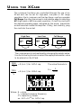
The crossover functions are controlled through the use of an
XCard and can be set for high-pass, low-pass or full range
operation. Each crossover card has two faces: one face operates
Full Range, the other has arrows to indicate the edge for selecting
HP (high-pass) or LP (low-pass) operation. Orient the card with
the desired operating edge, indicated by the arrow, toward the
socket terminals inside the amplifier. Firmly, but carefully, plug
the card into the socket.
High-Pass
➝
HP
HP
Full Range
➝
➝
LP
➝
Low-Pass
FULL ↕
LP
The crossover point can be altered by changing the resistor value.
Use the following formula to select the appropriate resistor value
to be placed on the XCard.
3386
fo
7234
fo
= R (in kΩ) for .047µf cap
The actual formula is:
1
2πfoc
R=
= R (in kΩ) for .022µf cap
Where: R = ohms
fo = desired crossover frequency
c = capacitor in farads
ex: .047 x 10-6 for .047µf cap
– 14 –
FULL
R2
R1
R2
R1
Crossover Card
High Pass
Low Pass
Full Range
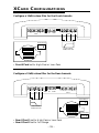
XC ARD C ONFIGURATIONS
Configure a 12dB/octave filter for the Front channels.
LED
+ L –
+ R – REM B+
– R +
– L +
Front
GND
Rear
Front XCard
HP
100Hz-20kHz
12dB/octave HP
XCard Rear 1
XCard Rear 2
XCard Pass-Thru
• Front XCard set to High-Pass or Low-Pass
Configure a 12dB/octave filter for the Rear channels.
LED
+ L –
+ R – REM B+
GND
– L +
Rear
– R +
Front
XCard Rear 1
LP
XCard Front
20Hz-100Hz
12dB/octave LP
XCard Pass-Thru
XCard Rear 2
Full
Range
• Rear XCard 1 set to High-Pass or Low-Pass
• Rear XCard 2 set to Full Range
– 15 –
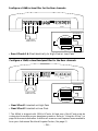
Configure a 24dB/octave filter for the Rear channels.
LED
+ L –
+ R – REM B+
– L +
– R +
Front
GND
Rear
XCard Rear 1
LP
XCard Front
20Hz-100Hz
24dB/octave LP
XCard Rear 2
XCard Pass-Thru
LP
• Rear XCards 1 & 2 set identically to High-Pass or Low-Pass
Configure a 12dB/octave Bandpass filter for the Rear channels.
LED
+ L –
+ R – REM B+
GND
Rear
– R +
– L +
Front
XCard Rear 1
HP
XCard Front
100Hz-275Hz
12dB/octave BP
XCard Pass-Thru
XCard Rear 2
LP
• Rear XCard 1 inserted as High-Pass
• Rear XCard 2 inserted as Low-Pass
* The 400x4 is shipped with 100Hz XCards. At least one of the XCards must be
customized to enable proper bandpass operation. Refer to “Using the XCard” on
page 14 for more information. Additional crossover card frequencies are available
from your Authorized Rockford Fosgate Dealer. (See page 2)
– 16 –
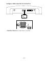
Configure a 12dB/octave filter for the Pass-Thru
Front
Gain
0/180
4/2
20Hz-100Hz
12dB/octave LP
XCard Front
XCard Rear1
XCard Rear2
XCard Pass-Thru
LP
• Pass-Thru XCard set to High-Pass or Low-Pass
– 17 –
Rear
Gain
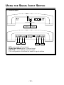
USING THE SIGNAL INPUT SWITCH
2-Channel Input
INPUT
1 2
Front
Gain
R
R
L
L
0°/180°
4/2
Input
Rear
Gain
Front Pass-Thru Rear
L - Summed
Output
R - Summed
Output
LED
+ L –
+ R – REM B+
GND
– L +
Rear
L
– R +
Front
R
L
R
• RCAs connected to Front inputs
• Signal Input Switch set to 2-channel input
• Pass-Thru is a non-fading summed output
• This configuration eliminates the need for signal splitters
– 18 –
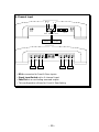
4-Channel Input
INPUT
1 2
Front
Gain
3
4
R
R
L
L
0°/180°
Rear
Gain
4/2
Input
Front Pass-Thru Rear
L - Summed
Output
R - Summed
Output
LED
+ L –
+ R – REM B+
GND
– L +
Rear
L
R
– R +
Front
R
R
L
F
• RCAs connected to Front & Rear inputs
• Signal Input Switch set to 4-channel input
• Pass-Thru is a non-fading summed output
• This configuration allows for Front & Rear fading
– 19 –
R
F
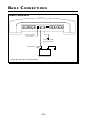
B ASI C C ON N E CT ION S
Power Connections
LED
+ L –
B+ GND
+ R –
– L +
Connect to remote
turn-on lead of
source unit
Connect to chassis
ground of vehicle*
Less than 18"
Connect to B+ of battery
with a 50 amp fuse
*Keep grounds as short as possible.
– 20 –
– R +
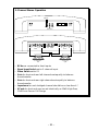
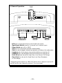
2-Channel Stereo Operation
INPUT
Front
Gain
0/180
4/2
Rear
Gain
Front
Rear
Pass-Thru
LED
+ L –
+ R – REM
B+ GND
Rear
+
–
– L +
– R +
Front
–
4 ohm min.
left
+
4 ohm min.
right
•
•
•
•
RCAs are connected to front inputs
Signal Input Switch set to 2-channel input
Phase Switch set to 0°
Gain for front and rear left channels set equally to balance
the subwoofer
• Gain for front and rear right channels set equally to balance
the subwoofer
• Impedance for each bridged channel should be no less than 4Ω
• XCards for front and rear are set identically as 12dB High-Pass,
12dB Low-Pass or Full Range
– 21 –
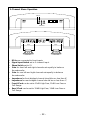
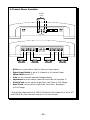
2-Channel Mono Operation
INPUT
Front
Gain
0/180
4/2
Rear
Gain
Front
Rear
Pass-Thru
LED
+ L –
+ R – REM B+
GND
Rear
+
–
–
4 ohm min.
•
•
•
•
•
•
•
•
•
– L +
– R +
Front
+
4 ohm min.
RCAs are connected to front inputs
Signal Input Switch set to 2-channel input
Phase Switch set to 0°
Gain for front left and right channels set equally to balance
the subwoofer
Gain for rear left and right channels set equally to balance
the subwoofer
Impedance for front bridged channel should be no less than 4Ω
Impedance for rear bridged channel should be no less than 4Ω
Front XCard can be set to 12dB High-Pass, 12dB Low-Pass or
Full Range
Rear XCard can be set to 12dB High-Pass, 12dB Low-Pass or
Full Range
– 22 –
INPUT
4-Ch.
3-Channel Operation
{
{
2-Ch.
Front
Gain
0/180
4/2
Rear
Gain
Front
Rear
Pass-Thru
LED
+ L –
+ R – REM B+
GND
–
–
+
Rear
+
4 ohm min.
•
•
•
•
•
•
•
•
•
L
+
– R +
Front
–
2 ohm min.
–
+
2 ohm min.
RCAs are connected to front or front and rear inputs
Signal Input Switch is set to 2-channel or 4-channel input
Phase Switch set to 0° or 180°*
Gain for front channels operate independently
Gain for rear bridged channels set equally to balance the subwoofer
Impedance for front stereo channels should be no less than 2Ω
Impedance for rear bridged channel should be no less than 4Ω
Front XCard can be set for High-Pass, Low-Pass or Full Range
Rear XCard can be set for High-Pass, Low-Pass, Bandpass
or Full Range
*Adjust the phase switch to 180° if XCard for front channel is set to HP
and XCard for rear channel is set to LP (or vice versa).
– 23 –
4-Channel Stereo Operation
{
INPUT
4-Ch.
{
2-Ch.
Front
Gain
0/180
4/2
Rear
Gain
Front
Rear
Pass-Thru
LED
+ L –
+ R – REM B+
–
GND
L
Rear
+
–
2 ohm min.
•
•
•
•
•
•
•
+
–
2 ohm min.
–
+
2 ohm min.
+
– R +
Front
–
+
2 ohm min.
RCAs are connected to front or front and rear inputs
Signal Input Switch is set to 2-channel or 4-channel input
Phase Switch set to 0° *
Gain for all channels operate independently
Impedance for each stereo channel should be no less than 2Ω
Front XCard can be set for High-Pass, Low-Pass or Full Range
Rear XCard can be set for High-Pass, Low-Pass , Bandpass
or Full Range
* Adjust the phase switch to 180° if XCard for front channel is set to HP
and XCard for rear channel is set to LP (or vice versa).
– 24 –
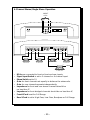
4-Channel Stereo/Single Mono Operation
{
INPUT
4-Ch.
{
2-Ch.
Front
Gain
0/180
Rear
Gain
4/2
Front
Rear
Pass-Thru
LED
+ L –
+ R – REM B+
–
GND
L
Rear
+
–
2 ohm min.
+
–
2 ohm min.
–
+
– R +
Front
+
–
2 ohm min.
–
+
2 ohm min.
+
4 ohm min.
•
•
•
•
•
•
RCAs are connected to front or front and rear inputs
Signal Input Switch is set to 2-channel or 4-channel input
Phase Switch set to 0°
Gain for front channels set equally to balance the subwoofer
Gain for rear channels operate independently
Impedance for front and rear stereo channels should be
no less than 2Ω
• Impedance for front bridged channels should be no less than 4Ω
• Front XCard is set for Full Range
• Rear XCard is set to High-Pass, Low-Pass, Bandpass or Full Range
– 25 –
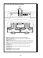
4-Channel Stereo/Dual Mono Operation
{
INPUT
4-Ch.
{
2-Ch.
Front
Gain
0/180
Rear
Gain
4/2
Front
Rear
Pass-Thru
LED
+ L –
+ R – REM B+
–
GND
L
Rear
+
–
+
–
2 ohm min.
2 ohm min.
+
–
+
– R +
Front
+
–
2 ohm min.
–
–
4 ohm min.
+
2 ohm min.
+
4 ohm min.
•
•
•
•
•
•
RCAs are connected to front or front and rear inputs
Signal Input Switch is set to 2-channel or 4-channel input
Phase Switch set to 0°
Gain for front left and right set equally to balance the subwoofer
Gain for rear left and right set equally to balance the subwoofer
Impedance for front and rear stereo channels should be
no less than 2Ω
• Impedance for front and rear bridged channels should be
no less than 4Ω
• Front XCard is set to Full Range
• Rear XCard is set to Full Range
– 26 –
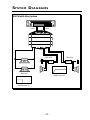
SYSTEM DIAGRAMS
200 Watt 3-Way System
Rear
Front
®
RFA-414
+
2X-4
–
+
–
RFA-414
–
–
a n a
+
+
•
+
–
+
2X-4
–
4
+
®
t r a n s
–
–
+
RFA-812
100Hz - 20kHz
12dB/octave HP
20Hz - 100Hz
24dB/octave LP
– 27 –
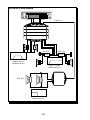
400 Watt 4-Way System
Rear
Front
Pass-Thru
®
–
–
RFA-414
+
–
2X-4
+
–
+
a n a
–
+
+
•
RFA-414
2X-4
+
–
+
12dB/octave LP
12dB/octave HP
–
100Hz - 275Hz
–
4
+
®
t r a n s
275Hz - 20kHz
12dB/octave HP
+
+
–
–
2
D S M
RFA-812
– 28 –
®
20Hz - 100Hz
24dB/octave LP
20Hz - 100Hz
24dB/octave LP
–
–
RFA-812
–
–
+
–
a n a
+
•
4
+
12dB/octave LP
12dB/octave HP
100Hz - 275Hz
+
+
®
t r a n s
2X-4
RFA-414
12dB/octave HP
275Hz - 20kHz
+ RFA-414 +
2X-4
–
–
–
+
®
+
–
+
–
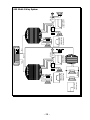
Rear
–
–
12dB/octave LP
12dB/octave HP
100Hz - 275Hz
+
+
®
•
4
t r a n s
–
+
a n a
2X-4
RFA-414
12dB/octave HP
275Hz - 20kHz
+ RFA-414 +
2X-4
–
–
®
+
–
–
+
Pass-Thru
–
– 29 –
+
Front
600 Watt 4-Way System
®
D S M
2
–
+
2X-4
RFA-414
12dB/octave HP
275Hz - 20kHz
+ RFA-414 +
2X-4
–
–
–
–
®
–
–
RFA-812
®
2X-4
RFA-414
Pass-Thru
12dB/octave HP
275Hz - 20kHz
+ RFA-414 +
2X-4
–
–
+
–
+
a n a
+
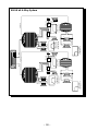
12dB/octave LP
12dB/octave HP
•
4
t r a n s
100Hz - 275Hz
+
+
20Hz - 100Hz
2
24dB/octave LP
D S M
20Hz - 100Hz
®
24dB/octave LP
RFA-812
–
–
+
–
a n a
+
•
4
+
12dB/octave LP
12dB/octave HP
100Hz - 275Hz
–
+
®
t r a n s
+
–
–
+
®
Rear
+
–
+
– 30 –
–
–
+
Pass-Thru
–
+
Front
800 Watt 4-Way System
®
D S M
2
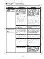
TROUBLESHOOTING
Symptom
Amplifier does not
turn on
(Power LED is off)
Amplifier has no
sound
(Power LED is on)
Diagnosis
Remedy
Voltage applied to the
REM terminal of the
amplifier is not between
10.5 and 15.5 volts or
there is no voltage
present.
Check the alternator, battery, fuse, and wiring and
repair as necessary. If the
voltage is above 15.5 volts,
have the electrical system
inspected by an authorized
car service center.
Voltage to the B+ terminal of the amplifier is
not between 10.5 and
15.5 volts or there is no
voltage present.
Check the alternator, battery, fuse, and wiring and
repair as necessary. If the
voltage is above 15.5 volts,
have the electrical system
inspected by an authorized
car service center.
Amplifier is not properly grounded.
Check wiring and repair as
necessary.
RCA Input from source
unit is not connected or
not functioning properly.
Check connections, substitute with known working
source and cables and repair
or replace as necessary.
XCard is missing or not
placed properly in crossover slots.
Check XCard position and
repair or replace as necessary.
Speaker leads are
shorted to each other or
to the chassis of the vehicle.
Disconnect existing speakers and test with known
working speakers and wires.
If amplifier plays, check and
repair wiring and installation of speakers as necessary.
Speakers are defective.
Disconnect existing speakers and test with known
working speakers. If amplifier plays, check and repair
speakers as necessary.
– 31 –
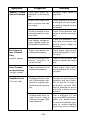
Symptom
Diagnosis
Remedy
Input gain signal for
amplifier is incorrectly
set.
Readjust input gains of
amplifier.
Source unit output too
low or source unit has
no output.
Check system with known
working source and repair
or replace original source
as needed.
XCard is missing or not
placed properly in crossover slots.
Check XCard position and
repair or replace as necessary.
Low battery voltage or
large voltage drops to
the amplifier under load.
Check the alternator, battery, fuse, and power and
ground wiring. Repair as
necessary.
No Output on
Rear Channels
Only
(using 2 inputs)
Signal input switch not
configured properly.
Check signal input switch
and reconfigure for 2-channel input.
XCard is missing or not
placed properly in
crossover slot.
Check XCard position and
repair or replace as necessary.
Rear Channels
are Non-Fading
(using 4 inputs)
Signal input switch not
configured properly.
Check signal input switch
and reconfigure for 4-channel input.
Amplifier Noise
(Turn-on Pop)
Voltage spike from output of preceding component is entering amplifier through input signal.
Disconnect input signal to
amplifier and turn amplifier on and off. If noise is
eliminated, connect REM
lead of amplifier to source
unit with a delay turn-on
module.
Voltage spike from remote turn-on lead is
entering through REM
input terminal.
Use a different 12 volt
source for REM lead of amplifier. (i.e., battery direct)
If noise is eliminated, use a
relay to isolate amplifier
from noisy turn-on output.
Speaker Output
Low or Distorted
– 32 –
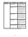
Symptom
Engine Noise
Diagnosis
Remedy
Noise is radiating into
RCA signal cable.
Check connections, run the
RCA cables on a different
route away from sources of
high voltage.
Bad component in the signal chain.
Check connections, bypass
additional components
(crossovers and equalizers)
between the source unit
and the amplifier. Connect
one component at a time
to determine the culprit.
Repair or replace components as necessary.
Noise is radiating into
speaker cables.
Disconnect existing speakers and connect a test
speaker to the output terminals of the amplifier. If
noise is gone, reroute the
speaker cables away from
sources of high voltage.
Multiple grounds in the
audio system.
Check ground connections
and connect amplifiers, signal processors, and other
components to a central
location or try a different
grounding point on the
chassis.
Ground loop between
source unit and antenna.
Check connections, disconnect antenna from
source unit. If noise is gone,
install an antenna ground
loop isolator.
• If noise persists, see your Authorized Rockford Fosgate Dealer.
– 33 –
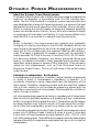
DYNAMIC POWER MEASUREMENTS
About the Dynamic Power Measurements
The Audio Graph PowerCube is a test instrument used to measure the
output of an amplifier in accordance with IHF-202 industry standards. The IHF-202 standard is a dynamic power measurement and
was developed as a means of measuring power in a manner that best
represents the real world operation of an amplifier. Many manufacturers, including Rockford Fosgate, at times will measure amplifier
power into a fixed resistor (4 ohm, 2 ohm). While this method is useful
in some types of evaluation and testing, it is not representative of an
amplifier that is connected to a speaker and playing music.
Music
Music is dynamic; the sound waves are complex and constantly
changing. In order to simulate this, the IHF-202 standard calls for the
input signal to the amplifier to be a 1kHz bursted tone. This signal is
input (on for 20 milliseconds) and reduced 20dB for 480 milliseconds. The signal is gradually increased in level until the amplifier's
output exceeds 1% Total Harmonic Distortion (THD). At 1% distortion becomes audible, therefore, any power produced above that
level is considered not usable. Many manufacturers represent their
amplifiers' output power in excess of 10% distortion. They use many
names for this measurement, such as Total Maximum Power or
Maximum Output Power. This is not indicative of the actual usable
output power.
Listening to Loudspeakers - Not Resistors
A loudspeaker is not a resistor. A resistor's value (resistance measured
in ohms) is fixed. A loudspeaker's impedance is dynamic. It is
constantly changing in value, dependent upon the frequency of the
input signal. Therefore, measuring power with the amplifier loaded
into a 4 ohm resistor is not the same as measuring power with the
amplifier connected to a 4 ohm speaker. Most people do not listen to
music through a resistor.
A 4 ohm speaker may experience a drop in impedance 4-6 times lower
than its nominal (printed) impedance. A speaker will also create phase
shifts in the signal that is passed through it. These phase shifts happen
because a speaker is an inductor (voice coil) and a capacitor (compliance of the surround/spider), as well as a resistor (voice coil wire).
To simulate a speaker the Audio Graph PowerCube measures output
power into 20 different loads. It tests at 8 ohms, 4 ohms, 2 ohms and
1 ohm. Each of these impedances is also tested at –60°, –30°, 0°, +30°
and +60° phase angles. These different impedances and phase angles
represent the shifts in impedance and phase that can occur in a typical
loudspeaker.
– 34 –
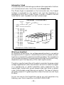
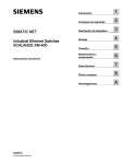
Information Cubed
The data acquired in the testing procedure is then graphed in the form
of a 3-dimensional cube. Hence the name PowerCube.
The Phase Angle is expressed on the horizontal axis, the Output
Voltage is presented on the vertical axis and the Impedance is
displayed on the Z axis. Output Power, in watts, is listed on the left
hand side for each impedance at each phase angle.
AudioGraph – The PowerCube™
x2 = STEREO
MONO = BRIDGED MONO
I M P E D A N C E
Amplifier: PUNCH 200ix 14.4V x 2
Serial No:
Owner : ROCKFORD CORPORATION
W
W
W
W
W
W
W
W
W
W
W
W
W
W
W
W
W
W
W
W
{
50V
POWER
IN
WATTS
30V
10V
8Ω
4Ω
–60° (Cap)
2Ω
0°
PHASE ANGLES
1Ω
(Ind) +60°
{
84
84
83
84
85
159
154
153
154
158
266
251
245
248
261
378
343
333
339
373
{
8Ω*–60°
–30°
0°
30°
60°
4Ω*–60°
–30°
0°
30°
60°
2Ω*–60°
–30°
0°
30°
60°
1Ω*–60°
–30°
0°
30°
60°
Rated Power : 100 W @ 4 Ohms
V O L T A G E
VOLTAGE FROM
BATTERY
O U T P U T
MODEL BEING
TESTED
e
danc
Impe
• Example of a 200ix PowerCube
What is an Amplifier?
An amplifier by definition is a voltage generating device, recreating
the signal which is input to it identically but with increased volume.
It will be connected to a reactive load (the speaker). The impedance
of this load and phase of the signal passing through the load will vary,
dependent upon the frequency of the input signal (music).
Therefore, a perfect amplifier will be able to maintain the same output
voltage regardless of load characteristics and will not alter the signal
it is reproducing. A perfect amplifier when measured by the
AudioGraph PowerCube would present data that forms a perfect
cube. Unfortunately, amplifiers are not perfect. The laws of physics
generally prevent it. A great amplifier is about the best one can hope
to attain.
As you can see by the PowerCube and as you will experience by
listening, your Punch amplifier is a GREAT AMPLIFIER!
– 35 –
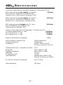
400X4 S P E C I F I C A T I O N S
Continuous Power Rating (Competition Standard) – Measured at 13.8V
RMS continuous power per channel, all channels
50 Watts
driven into a 4Ω load from 20-20,000Hz with
less than 0.05% Total Harmonic Distortion (THD)
RMS continuous power per channel, all channels
driven into a 2Ω load from 20-20000Hz, with
less than 0.1% Total Harmonic Distortion (THD)
100 Watts
RMS continuous power bridged into a 4Ω load
from 20-20000Hz, with less than 0.1%
Total Harmonic Distortion (THD)
200 Watts
Dynamic Power Rating (IHF-202 Standard) – Measured at 14.4V
2-Channel bridged into a 4Ω load
260 Watts
per channel into a 2Ω load
130 Watts
per channel into a 4Ω load
60 Watts
Signal-to-Noise Ratio (A-weighted)
>95dB
Factory Default Crossover Point
Crossover Alignment
Dimensions
100Hz Butterworth
12dB/octave
95⁄8"W x 135⁄8"L x 25⁄8"H
(24.4cm) x (34.6cm) x (6.6cm)
Damping Factor @ 4Ω (at output connector)
Bandwidth
Frequency Response
Slew Rate
IM Distortion (IHF)
Input Sensitivity
>150
15Hz-100kHz ±3dB
20Hz-20kHz ±0.5dB
30 V/µs
<0.05%
Variable from 150mV to 3V
Preset at the factory for 500mV
B+ Fuse Size (external to amplifier)
AGU 50 amp
Input Impedance
20k ohms
– 37 –
W A R R A N T Y I N F O R M AT I O N
Rockford Fosgate warrants all electronics to the original consumer/purchaser to
be free from defects in materials or workmanship for a period of three (3) years.
We will cover parts and labor provided the product was purchased from an
Authorized Rockford Fosgate Dealer. This warranty does not apply to any product
on which the seals and/or serial number have been broken, removed, tampered
with, defaced or altered in any manner. This warranty only applies to the original
consumer/purchaser and is not transferable.
Electronics found to be defective during the warranty period will be repaired or
replaced at Rockford Fosgate’s discretion. Repaired or replaced electronics will
be covered by the balance of the original warranty period only. Rockford Fosgate
shall not be responsible for any incidental or consequential damages resulting
from a defect in electronics. Some states do not allow the exclusion or limitation
of incidental or consequential damages, so the previous limitation may not be
applicable.
The warranty does not cover any appearance item, any cost or expense related to
the removal or reinstallation of the product, any accessory used in conjunction
with the product, damage to the product resulting from alteration, accident,
misuse or abuse, or improper installation. This warranty does not apply if the parts
or labor, which would otherwise be provided without charge under this warranty,
are obtained from any source other than Rockford Fosgate or an Authorized
Rockford Fosgate Service Center.
This warranty is the only express warranty and does not create any implied
warranties. Rockford Fosgate limits its obligations under any implied warranties
under state laws to a period not to exceed the written warranty period. Some states
do not allow limitation on how long an implied warranty lasts, so the above
limitation may not apply. This warranty applies only to products sold in the United
States of America or its possessions. For warranty outside the U.S.A., please
contact the nearest Authorized Rockford Fosgate Dealer. This warranty gives the
consumer specific legal rights, and the consumer may have other rights which vary
from state to state.
A defective product must be shipped prepaid to the Authorized Rockford Fosgate
Dealer from which the consumer purchased the product or to the Rockford
Fosgate factory in Tempe, Arizona in the original factory carton or equivalent. Any
shipping loss or damage will be borne by the consumer or the consumer’s shipper.
A consumer returning a product to the factory must call (800) 669-9899 for a
Return Authorization Number. All shipments shall be clearly marked with the
Return Authorization Number on the outside of the shipping carton.
Ship to:
Rockford Corporation
Warranty Repair Department
2055 E. 5th Street
Tempe, AZ 85281 U.S.A.
Return Authorization Number:_________________
NOTES
NOTES
Rockford Fosgate
Rockford Corporation
546 South Rockford Drive
Tempe, Arizona 85281 U.S.A.
In U.S.A., (602) 967-3565
In Europe, Fax (49) 4207-801250
In Japan, Fax (81) 559-79-1265
6/95
MAN-0993-A