1
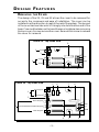
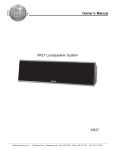
2X, 3 X AND 5X E LECTRONIC CROSSOVER O W N E R ’S MANUAL Dear Customer, Congratulations on your purchase of America’s finest brand of car audio components. At Rockford Fosgate we are committed to musical reproduction at its best, and we are pleased you chose our product. Through years of engineering expertise, hand craftsmanship and critical testing procedures we have created a wide range of products that reproduce music with all the clarity and richness you deserve. For maximum performance we recommend you have your new Rockford Fosgate product installed by an Authorized Rockford Fosgate Dealer, as we provide specialized training through Rockford Technical Training Institute (RTTI). Please read your warranty and retain your receipt and original carton for possible future use. To add the finishing touch to your new Rockford Fosgate image order your Rockford wearables, which include everything from T-shirts and jackets to hats and sunglasses. To get a free brochure on Rockford Fosgate products and Rockford accessories, please call 1-800-366-3565 or FAX 1-602-966-3983 in the U.S. For Canada, call Korbon Trading at 905-567-1920. For international orders FAX 001-1-602-9678132 or call 001-1-602-967-3565. PRACTICE SAFE SOUND™ CONTINUOUS EXPOSURE TO SOUND PRESSURE LEVELS OVER 100dB MAY CAUSE PERMANENT HEARING LOSS. HIGH POWERED AUTO SOUND SYSTEMS MAY PRODUCE SOUND PRESSURE LEVELS WELL OVER 130dB. USE COMMON SENSE AND PRACTICE SAFE SOUND. If, after reading your manual, you still have questions regarding this product, we recommend that you see your Rockford Fosgate dealer. If you need futher assistance, you can call us direct at 1-800-795-2385. Be sure to have your serial number, model number and date of purchase available when you call. The serial number can be found on the outside of the box. Please be sure to record it in the space provided below as your permanent record. This will serve as verification of your factory warranty and become useful in recovering your product if ever stolen. Serial Number: __________________________________________ Model Number: ___________________________________ TABLE OF CONTENTS Punch 2X, 3X and 5X Packing List ................................................ 1 Introduction ................................................................................. 1 Operating Features ................................................................. 1 Design Features ............................................................................ 2 1. Gold Plated RCA Jacks ....................................................... 3 2. Power Terminals ................................................................ 3 3. LED Power Indicator .......................................................... 3 4. PROCards .......................................................................... 3 5. Input Mode Switch (3X and 5X only) .................................. 3 6. Phase Switch (3X and 5X only) ........................................... 4 7. Mounting Holes ................................................................. 4 8. Fusing ................................................................................ 4 Installation Considerations ........................................................... 5 Mounting and Wiring the Active Crossover .................................. 6 B+ .......................................................................................... 6 GND ...................................................................................... 6 REM ....................................................................................... 6 Input/Output Levels & Connections ........................................ 6 Selecting the PROCards ............................................................... 7 Using The Dual Filter (3X and 5X only) ........................................ 8 Installing the PROCards ............................................................... 8 Filter Effects .................................................................................. 9 Wiring Diagrams ........................................................................ 10 Appendix A - Building A Custom PROCard ................................ 18 Butterworth Resistor Chart .......................................................... 19 Specifications ............................................................................. 20 Warranty .................................................................................... 21 P U N C H 2X/3X/5X P A C K I N G L I S T Punch Electronic Crossover Owner's Manual INTRODUCTION This manual provides information on the features, installation and operation of the Punch 2X, 3X and 5X Electronic Crossover. We suggest you save this manual for future reference. We strongly recommend you have your Authorized Rockford Fosgate Dealer install your new active crossover. If you do choose to install the unit yourself, please be sure to read the entire manual before beginning your installation. OPERATING FEATURES The Punch 2X, 3X and 5X Electronic Crossovers provide for state-ofthe-art flexibility and performance demanded by today’s car audio enthusiasts. Features include: PROCards – 3-Way Selectable Electronic Crossover modules that feature 12dB per octave filters that give precise crossover points and allow for individual selection of high-pass, low-pass or full range filter operation. Dual Filtered, Non-Faded Output with Phase Reversal Switch (3X and 5X only) allows you to create various pass band configurations. In addition, the phase reversal switch enables you to easily correct for phase problems that may be inherent in some system designs. 2 Channel Input on the Punch 2X 2 or 4-Channel Input Mode Switch (3X and 5X only) enables you to select two (2) or four (4) channels of input. 4 Outputs on the Punch 2X 6 Outputs on the Punch 3X for Front, Rear and a Dual-Filtered, NonFaded Output. 10 Outputs on the Punch 5X – In addition to the outputs found on the Punch 3X, the 5X also has Front and Rear Dual-Filtered Outputs for creating additional pass band filter combinations. Gold Plated RCA Input and Output Jacks reduce corrosion which can cause signal deterioration over time. –1– D E S I G N F E AT U R E S REMOVING THE COVER The design of the 2X, 3X and 5X allows the cover to be removed for access to the crossovers and ease of installation. The cover can be installed in either direction to match the rest of the system. The top end of the cover has two tabs which fit snugly into slots at either end of the base. Care must be taken not to bend the securing tabs when removing the top cover. A screw secures the cover. Remove this screw to release the cover for removal. Punch 2X - Top Inside View 8 1 Input 3 Rem Output B+ 1 GND Output 4 Punch 3X - Top Inside View 5 7 6 2 7 8 Front Input 1 Rear Input 3 Front Output Rem 1 Dual Filtered Non-Faded Output B+ GND Rear Output 4 –2– 7 2 Punch 5X - Top Inside View 5 7 6 8 Front Input 1 Rear Input 3 Front Output Front Dual-Filtered Output 1 Dual Filtered Non-Faded Output Rem B+ Rear Dual-Filtered Output GND Rear Output 4 7 2 1. Gold Plated RCA Jacks All input and output RCA jacks are gold plated. The gold plated finish resists tarnishing and corrosion from interfering with the signal quality. 2. Power Terminals The B+, Rem and Gnd connections are made using gold plated screw terminals on the barrier strip. The gold plating resists tarnish and corrosion and maintains connection integrity. The terminals allow easy connection of the power wires through the use of forked lugs or bare wire up to 12 gauge. The barriers help prevent shorting from frayed wires. 3. LED Power Indicator The LED, located by the input jacks, provides a visual indication of the status of the crossover, lighting when the unit is turned on. 4. PROCards Crossover filter functions are determined by the use of plug in cards. Each card can be configured for high-pass, low-pass and full range operation. Resistors on each module determine the operating frequency. 5. Input Mode Switch (3X and 5X only) When the input mode switch is in the two channel position the front input jacks feed all the filters. When set to the four channel position, the front and rear input jacks feed the respective filters. Front and rear channels are summed for the non-faded filter. –3– 6. Phase Switch (3X and 5X only) The phase switch allows easy invertion polarity on the non-faded output to optimize sound quality. 7. Mounting Holes The crossover must be mounted on a flat surface. Two mounting holes in the bottom are used to secure the crossover. 8. Fusing The crossover has a 1/2 amp AGC fast blow power protection fuse. If it is necessary to replace the fuse, use only the same type and rating or the warranty may be voided. –4– I N S TA L L A T I O N C O N S I D E R A T I O N S This section focuses on some of the vehicle considerations for installing your new Punch Electronic Crossover. Checking your battery and current sound system, as well as pre-planning your system layout and best wiring routes will save installation time. When deciding how to lay out your new system, be sure that each component will be easily accessible for making adjustments. Before beginning any installation, be sure to follow these simple rules: 1. Be sure to carefully read and understand the instructions before attempting to install the crossover. 2. For safety, disconnect the negative lead from the battery prior to beginning the installation. 3. For easier assembly, we suggest you run all wires prior to mounting your electronic crossover in place. 4. Route all of the RCA cables close together and away from any high current wires. this will help reduce noise. 5. Use high quality connectors for a reliable installation and to minimize signal or power loss. See your Authorized Rockford Fosgate Dealer for wire enhancements. 6. Think before you drill! Be careful not to cut or drill into gas tanks, fuel lines, brake or hydraulic lines, vacuum lines or electrical wiring when working on any vehicle. 7. Never run wires underneath the vehicle. Running the wires inside the vehicle provides for best protection. 8. Avoid running wires over or through sharp edges. Use rubber or plastic grommets to protect any wires routed through metal, especially the firewall. 9. ALWAYS protect the battery and electrical system from damage with proper fusing. Install a fuse holder and fuse on the +12V power wire within 18” (45.7 cm) of the battery terminal. 10. When grounding to the chassis of the vehicle, scrape all paint from the metal to ensure a good, clean ground connection. Grounding connections should be as short as possible and always be connected to metal that is welded to the main body, or chassis, of the vehicle. Use of a continuity meter will confirm a proper ground. –5– MOUNTING AND WIRING THE ELECTRONIC CROSSOVERS The information below describes the various considerations for mounting and connecting the active crossovers. For additional information see the wiring diagrams beginning on page 10. We recommend mounting the crossover as close to the amplifier(s) as possible. The B+ (Power) supplies power to the unit. Connect this terminal to a constant +12 Volt power source by way of an in-line fuse. The GND (Power Ground) grounds the unit. Connect this terminal to the chassis of the vehicle. When grounding the unit be sure to scrape all paint from the metal to ensure a clean electrical connection. The REM (Remote Turn-On) turns on the unit by way of a +12 Volt supply source. Connect this terminal to the source unit’s “Amplifier” or “Auto Antenna” lead, either of which will go to +12 volts whenever the source unit is on. If your source unit does not have either a Remote or an Auto Antenna lead (or if the Auto Antenna goes down during tape operation), we recommend installing a switch to control the unit manually. INPUT/OUTPUT LEVELS & CONNECTIONS The Punch Electronic Crossovers are designed for preamp (input up to 2VRMS) levels. Net gain in the crossover is unity. (Output levels are equal to input levels.) When connecting the input and output terminals be sure to use high quality shielded interconnecting RCA cables. • Connect source unit's OUTPUT jacks to the desired crossover INPUT jacks. • Connect the desired crossover’s OUTPUT jacks to the Amplifier’s INPUT jacks. –6– S ELECT I N G T HE PROC A RDS The Punch 2X is shipped with 100Hz cards. The 3X is shipped with 100Hz and blank programmable cards and the 5X is shipped with 100Hz, 6.5kHz and blank programmable cards. The following cards are available factory built from your Authorized Rockford Fosgate Dealer. XM50 XM70 XM100 XM150 XM200 XM275 XM400 XM4.5k XM6.5k 50Hz 70Hz 100Hz 150Hz 200Hz 275Hz 400Hz 4.5kHz 6.5kHz Each card can be used for high-pass, low-pass or full range operation. The mode of operation is determined by the orientation of the ProCard in its socket. These same PROCards are used in other Rockford Fosgate products. The following illustrations show the PROCards shipped in the Punch 2X, 3X and 5X. As configured, out of the box, each card is set for full range operation. Punch 2X Output Output 100 Hz 100 Hz Punch 3X 100 Hz Front Output Dual Filtered Non-Faded Output Rear Output 100 Hz 100 Hz –7– Blank Punch 5X 6.5kHz Front Output Front Dual Filtered Output Dual Filtered Non-Faded Output Rear Dual Filtered Output THE Blank 100Hz Blank 100Hz Blank 6.5kHz Rear Output USING 100Hz D U A L F I LT E R The Punch 3X and the Punch 5X both have Dual Filter sections. The Dual Filter is a two stage cascaded filter which uses two PROCards. The first card determines the initial action and the second, the subsequent action. The most common usage would be to use a lowpass module in the first position followed by a high-pass module in the second to build a bandpass function. By using two cards of the same action at the same frequency, the filter slope is increased to 24dB per octave. Both sockets must be used for a simple 12dB per octave filter. Install the card in the second position for full range operation. I NSTALLING THE PROC ARDS The operation of each filter section is determined by the use of plug in cards. These multifunctional cards are available for a multitude of operational frequencies, and their orientation in the socket determines their function. Each socket has a blank plastic side which positions the card against the spring loaded contacts. The front, or active, face of the card is marked with arrows to indicate which edge plugs into the socket. Orient the card with the chosen face toward the contacts and plug it into the socket of the appropriate filter operation. The rear face of the card is for full range operation and either edge can be used. –8– F I LT E R EF F E C T S Example: The Punch 3X ships with three (3) 100Hz PROCards set in the Full Range position. The crossover will pass through all 20Hz 20kHz frequencies. The following diagram shows examples of the types of response curves when programming for a High-Pass, LowPass or Bandpass setting. Gain (dB) 20Hz 20kHz High-Pass Crossover Setting Response Gain (dB) 20Hz 20kHz Low-Pass Crossover Setting Response Gain (dB) 20Hz 20kHz Bandpass Crossover Setting Response (3X and 5X only) Note: The Punch 3X and 5X Dual-Filtered Output Channels contain a blank crossover card. As with the Front and Rear Outputs, the default positioning for these cards is set at Full Range. –9– WIRING DIAGRAMS 2X Basic System Source Unit Low-Pass High-Pass ® ® 2 2X Crossover ® ® Midrange/ Tweeter – + – + High-Pass @ 12dB/octave slope Midrange/ Tweeter 2-Channel Amplifier ® ® + – + – + – 2-Channel Amplifier FIGURE 1 – 10 – Midrange/ Woofer 4Ω Low-Pass @ 12dB/octave slope 2X - 2 Way with Passive Crosovers Source Unit Low-Pass High-Pass ® ® 2 ® – + – + ® High-Pass @ 12dB/octave slope Tweeter 2X Crossover Passive Crossover Midrange Passive Crossover Midrange 2-Channel Amplifier Tweeter + ® ® – – + – + Woofer 4Ω – Woofer 4Ω 2-Channel Amplifier + FIGURE 2 – 11 – Low-Pass @ 12dB/octave slope 3X – 2-Way with Passive Crossovers Source Unit 2 0° 4* 180°** High-Pass Low-Pass Low-Pass High-Pass ® ® 3 High-Pass Crossover 3x Crossover Tweeter Rear High-Pass @ 12dB/octave slope ® ® Midrange – + – + Midrange 2-Channel Amplifier Tweeter + High-Pass Crossover Subwoofer ® ® Summed Output @ 24dB/octave slope – – + – + – 2-Channel Amplifier Subwoofer High-Pass Crossover + Tweeter ® ® Midrange – + – + Midrange 2-Channel Amplifier Tweeter High-Pass Crossover *2 or 4 Channel can be selected if user desires fader capability. ** Try Phase Switch for summed output and set to position that sounds best. FIGURE 3 – 12 – Front High-Pass @ 12dB/octave slope 3X – 3-Way Basic System Source Unit 2 0° 4* 180°** High-Pass Low-Pass High-Pass Low-Pass ® ® 3 3x Crossover + ® Subwoofer ® – + – + – Low-Pass @ 12dB/octave slope – Subwoofer 2-Channel Amplifier + ® Midrange ® – + – + Bandpass Output @ 12dB/octave slope Midrange ® ® 2-Channel Amplifier – + – + Tweeter Tweeter 2-Channel Amplifier * Try Phase Switch for summed output and set to position that sounds best. FIGURE 4 – 13 – High-Pass Output @ 12dB/octave slope 3X – 2-Way with Amplifier's Active Crossover Source Unit 2 0° 4* 180°** High-Pass Low-Pass Low-Pass High-Pass ® ® 3 3x Crossover ® D S M 4 4 ® Tweeter – + – + – + – + Tweeter Midrange 4-Channel Amplifier with Crossover*** (High-Pass) (Low-Pass) Rear Bandpass Both rolloffs @ 12dB/octave slope Midrange Summed Output @ 24dB/octave slope – ® ® Rear High-Pass @ 12dB/octave slope – + – + Subwoofer + 2-Channel Amplifier ® 4 4 D S M ® Tweeter 4-Channel Amplifier with Crossover*** (High-Pass) (Low-Pass) – + – + – + – + Front High-Pass @ 12dB/octave slope Tweeter Midrange Front Bandpass Both rolloffs @ 12dB/octave slope Midrange *2 or 4 Channel can be selected if user desires fader capability. ** Try Phase Switch for summed output and set to position that sounds best. *** Additional filtering provided by internal crossovers in the amplifiers. FIGURE 5 – 14 – 5X – Basic System Source Unit 2 0° 4* 180°** High-Pass Low-Pass ® ® 5 High-Pass Low-Pass Low-Pass Low-Pass High-Pass High-Pass ® ® 5x Crossover – + Tweeter – + Tweeter Rear High-Pass @ 12dB/octave slope 2-Channel Amplifier Midrange ® ® – + – + Front Bandpass Both rolloffs @ 12dB/octave slope Midrange ® 2-Channel Amplifier ® – + – + Summed Output @ 24dB/octave slope – Subwoofer + ® ® 2-Channel Amplifier – + – + Midrange Front Bandpass Both rolloffs @ 12dB/octave slope Midrange ® ® 2-Channel Amplifier – + Tweeter – + Tweeter Front High-Pass @ 12dB/octave slope 2-Channel Amplifier *2 or 4 Channel can be selected if user desires fader capability. ** Try Phase Switch for summed output and set to position that sounds best. FIGURE 6 – 15 – 5X – 2-Way with 24dB Slopes Source Unit 2 0° 4* 180°** Not Used High-Pass Not Used High-Pass Low-Pass Low-Pass High-Pass High-Pass ® Not Used ® 5 5x Crossover Not Used ® ® Midrange/Tweeter – + – + Rear High-Pass @ 24dB/octave slope Midrange/Tweeter ® ® 2-Channel Amplifier – + – + – Summed Output @ 24dB/octave slope Subwoofer + 2-Channel Amplifier ® ® Midrange/Tweeter – + – + Midrange/Tweeter 2-Channel Amplifier *2 or 4 Channel can be selected if user desires fader capability. ** Try Phase Switch for summed output and set to position that sounds best. FIGURE 7 – 16 – Front High-Pass @ 24dB/octave slope 5X – 4-Way System Source Unit 2 0° 4 180°** Not Used Low-Pass ® ® 5 High-Pass Low-Pass Low-Pass Low-Pass High-Pass High-Pass ® ® 5x Crossover – + Tweeter – + Tweeter High-Pass @ 12dB/octave slope 2-Channel Amplifier Midrange ® ® – + – + Bandpass Both rolloffs @ 12dB/octave slope Midrange ® 2-Channel Amplifier ® – + – + Low-Pass @ 24dB/octave slope – Subwoofer + ® ® 2-Channel Amplifier – + – + Mid Bass Bandpass Both rolloffs @ 12dB/octave slope Mid Bass 2-Channel Amplifier Not Used** *2 or 4 Channel can be selected if user desires fader capability. ** Try Phase Switch for summed output and set to position that sounds best. FIGURE 8 – 17 – APPENDIX A B UILDING A C USTOM PROC ARD The 3X and 5X both ship with blank cards which can be assembled to select any frequency you need for your system's design. Each card is built using 4 capacitors and 4 resistors, the value of the resistors determines the operating frequency. The custom cards are also available as model number XM00 from your Authorized Rockford Fosgate Dealer. The following section has instructions on assembling the card. The PC Board is fragile and extra care should be taken to avoid damage. Items Needed: 1. Soldering Pencil 40 to 60 Watt electronic soldering iron 2. 60/40 resin core solder 3. Solder Braid - to keep surface free of excess solder 4. Capacitors - Each card uses four .022µF capacitors. These should be metal film capacitors with a minimum rating of 16 volts. 5. Resistors - Each card uses four resistors. The resistance is determined by the operating frequency (refer to the following chart). These can be either 1/8 or 1/4 Watt, 1% or 5% tolerance. 6. Wire Cutters Refer to the following illustration for component placement. Install the resistors, from the full range face, and fold the leads slightly toward the inside of the board to hold them in position. Solder the resistors in place and use the solder braid to remove any excess solder. Install the capacitors in the same manner. Trim the component leads. Examine the board carefully to ensure there is no solder splashed, paying particular attention to the contacts on each edge. Make sure that the leads do not interfere when plugging the card into the socket. – 18 – R2 R1 R2 R1 Crossover Card High Pass Low Pass Full Range FULL Electronic Crossover Field Programmable Card Resistor Chart Butterworth Alignment Use 5% resistors in conjunction with .022µF standard capacitor. Low Pass Freq. 18.5Hz 26Hz 33Hz 40Hz 48Hz 60Hz 72Hz 88Hz 106Hz 130Hz 154Hz 185Hz 220Hz 270Hz 330Hz 400Hz 480Hz 600Hz 720Hz 880Hz 1.06kHz 1.3kHz 1.54kHz 1.85kHz 2.2kHz 2.7kHz 3.3kHz 4.0kHz 4.8kHz 6.0kHz 7.2kHz 8.8kHz 10.6kHz 13.0kHz 15.4kHz R1 390k Ohm 270k Ohm 220k Ohm 180k Ohm 150k Ohm 120k Ohm 100k Ohm 82k Ohm 68k Ohm 56k Ohm 47k Ohm 39k Ohm 33k Ohm 27k Ohm 22k Ohm 18k Ohm 15k Ohm 12k Ohm 10k Ohm 8.2k Ohm 6.8k Ohm 5.6k Ohm 4.7k Ohm 3.9k Ohm 3.3k Ohm 2.7k Ohm 2.2k Ohm 1.8k Ohm 1.5k Ohm 1.2k Ohm 1k Ohm 820 Ohm 680 Ohm 560 Ohm 470 Ohm R2 390k Ohm 270k Ohm 220k Ohm 180k Ohm 150k Ohm 120k Ohm 100k Ohm 82k Ohm 68k Ohm 56k Ohm 47k Ohm 39k Ohm 33k Ohm 27k Ohm 22k Ohm 18k Ohm 15k Ohm 12k Ohm 10k Ohm 8.2k Ohm 6.8k Ohm 5.6k Ohm 4.7k Ohm 3.9k Ohm 3.3k Ohm 2.7k Ohm 2.2k Ohm 1.8k Ohm 1.5k Ohm 1.2k Ohm 1k Ohm 820 Ohm 680 Ohm 560 Ohm 470 Ohm – 19 – High Pass R1 390k Ohm 270k Ohm 220k Ohm 180k Ohm 150k Ohm 120k Ohm 100k Ohm 82k Ohm 68k Ohm 56k Ohm 47k Ohm 39k Ohm 33k Ohm 27k Ohm 22k Ohm 18k Ohm 15k Ohm 12k Ohm 10k Ohm 8.2k Ohm 6.8k Ohm 5.6k Ohm 4.7k Ohm 3.9k Ohm 3.3k Ohm 2.7k Ohm 2.2k Ohm 1.8k Ohm 1.5k Ohm 1.2k Ohm 1k Ohm 820 Ohm 680 Ohm 560 Ohm 470 Ohm R2 390k Ohm 270k Ohm 220k Ohm 180k Ohm 150k Ohm 120k Ohm 100k Ohm 82k Ohm 68k Ohm 56k Ohm 47k Ohm 39k Ohm 33k Ohm 27k Ohm 22k Ohm 18k Ohm 15k Ohm 12k Ohm 10k Ohm 8.2k Ohm 6.8k Ohm 5.6k Ohm 4.7k Ohm 3.9k Ohm 3.3k Ohm 2.7k Ohm 2.2k Ohm 1.8k Ohm 1.5k Ohm 1.2k Ohm 1k Ohm 820 Ohm 680 Ohm 560 Ohm 470 Ohm S P E C I F I C AT I O N S Maximum Input Level Input Impedance Maximum Output Level Output Impedance Frequency Response 2V RMS 20,000Ω 2V RMS 500Ω 20Hz to 20kHz +0dB –0.5dB >105dB <0.02% THD + Noise >75dB 4.8" x 2.9" x 1.8" 12.19cm x 7.37cm x 4.57cm 4.8" x 4.1" x 1.8" 12.19cm x 10.41cm x 4.57cm 4.8" x 5.55" x 1.8" 12.19cm x 10.41cm x 4.57cm 100Hz (2X/3X) 100Hz & 6.5kHz (5X) 12dB per octave Butterworth Signal to Noise Ratio Distortion Channel Separation Dimensions Punch 2X Punch 3X Punch 5X Factory Equipped ProCards Crossover Slope Factory Supplied Alignment Specifications subject to change. – 20 – W A R R A N T Y IN F O R M AT I O N Rockford Fosgate warrants all electronics to the original consumer/purchaser to be free from defects in materials or workmanship for a period of three (3) years. We will cover parts and labor provided the product was purchased from an Authorized Rockford Fosgate Dealer. This warranty does not apply to any product on which the seals and/or serial number have been broken, removed, tampered with, defaced or altered in any manner. This warranty applies only to the original consumer/purchaser and is not transferable. Electronics found to be defective during the warranty period will be repaired or replaced at Rockford Fosgate’s discretion. Repaired or replaced electronics will be covered by the balance of the original warranty period only. Rockford Fosgate shall not be responsible for any incidental or consequential damages resulting from a defect in electronics. Some states do not allow the exclusion or limitation of incidental or consequential damages, so the previous limitation may not be applicable. The warranty does not cover any appearance item, any cost or expense related to the removal or reinstallation of the product, any accessory used in conjunction with the product, damage to the product resulting from alteration, accident, misuse or abuse, or improper installation. This warranty does not apply if the parts or labor, which would otherwise be provided without charge under this warranty, are obtained from any source other than Rockford Fosgate or an Authorized Rockford Fosgate Service Center. This warranty is the only express warranty and does not create any implied warranties. Rockford Fosgate limits its obligations under any implied warranties under state laws to a period not to exceed the written warranty period. Some states do not allow limitation on how long an implied warranty lasts, so the above limitation may not apply. This warranty applies only to products sold in the United States of America or its possessions. For warranty outside the U.S.A., please contact the nearest Authorized Rockford Fosgate Dealer. This warranty gives the consumer specific legal rights, and the consumer may have other rights which vary from state to state. A defective product must be shipped prepaid to the Authorized Rockford Fosgate Dealer from which the consumer purchased the product or to the Rockford Fosgate factory in Tempe, Arizona in the original factory carton or equivalent. Any shipping loss or damage will be borne by the consumer or the consumer’s shipper. A consumer returning a product to the factory should call (800) 669-9899 for a Return Authorization Number. All shipments shall be clearly marked with the Return Authorization Number on the outside of the shipping carton. Ship to: Rockford Corporation Warranty Repair Department 2055 E. 5th Street Tempe, AZ 85281 U.S.A. Return Authorization Number:__________________________ NOTES NOTES Rockford Fosgate A Division of Rockford Corporation 546 South Rockford Drive Tempe, Arizona 85281 U.S.A. In U.S.A. (602) 967-3565 In Canada, call Korbon (905) 567-1920 In Europe, Fax (49) 4207-801250 MAN-0628-A 1/94