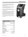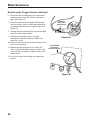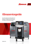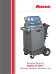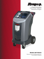
1
Original Instructions
Instrucciones originales
Instructions d’origine
Model AC1234-6
Recover, Recycle, Recharge Machine
for R1234yf A/C Systems
Description: Recover, recycle, and recharge machine for use
with R1234yf equipped air conditioning systems.
PRODUCT INFORMATION
Record the serial number and year of manufacture of this unit for future reference. Refer to the
product identification label on the unit for information.
AC1234-6
Serial Number:________________________________Year of Manufacture:_____________
DISCLAIMER: Information, illustrations, and specifications contained in this manual are based on the latest information available
at the time of publication. The right is reserved to make changes at any time without obligation to notify any person or organization
of such revisions or changes. Further, ROBINAIR shall not be liable for errors contained herein or for incidental or consequential
damages (including lost profits) in connection with the furnishing, performance, or use of this material. If necessary, obtain additional
health and safety information from the appropriate government agencies, and the vehicle, refrigerant, and lubricant manufacturers.
Table of Contents
Safety Precautions . . . . . . . . . . . . . . . . . . . . . . . . . . . . . . . . . . . . . . . . . . . 2
Introduction
Technical Specifications . . . . . . . . . . . . . . . . . . . . . . . . . . . . . . . . . . . . . 5
Features of the AC1234-6 . . . . . . . . . . . . . . . . . . . . . . . . . . . . . . . . . . . . 6
Control Panel Functions . . . . . . . . . . . . . . . . . . . . . . . . . . . . . . . . . . . . . 8
Setup Menu Functions . . . . . . . . . . . . . . . . . . . . . . . . . . . . . . . . . . . . . . 9
Setup
Unpack the Accessory Kit . . . . . . . . . . . . . . . . . . . . . . . . . . . . . . . . . . . 10
Install Oil Drain Bottle . . . . . . . . . . . . . . . . . . . . . . . . . . . . . . . . . . . . . . 10
Power Up the Machine . . . . . . . . . . . . . . . . . . . . . . . . . . . . . . . . . . . . . 11
Register the Machine . . . . . . . . . . . . . . . . . . . . . . . . . . . . . . . . . . . . . . 11
Language Selection . . . . . . . . . . . . . . . . . . . . . . . . . . . . . . . . . . . . . . . 12
Unit of Measure . . . . . . . . . . . . . . . . . . . . . . . . . . . . . . . . . . . . . . . . . . 12
Date & Time Setup . . . . . . . . . . . . . . . . . . . . . . . . . . . . . . . . . . . . . . . . 12
Service Installation Clearing . . . . . . . . . . . . . . . . . . . . . . . . . . . . . . . . . 12
Tank Fill Adjustment . . . . . . . . . . . . . . . . . . . . . . . . . . . . . . . . . . . . . . . 13
Tank Filling . . . . . . . . . . . . . . . . . . . . . . . . . . . . . . . . . . . . . . . . . . . . . . 13
Garage Data . . . . . . . . . . . . . . . . . . . . . . . . . . . . . . . . . . . . . . . . . . . . . 14
Operating Instructions
VIN Entry . . . . . . . . . . . . . . . . . . . . . . . . . . . . . . . . . . . . . . . . . . . . . . . 15
Stored Data . . . . . . . . . . . . . . . . . . . . . . . . . . . . . . . . . . . . . . . . . . . . . . 15
Diagnostic Pressures . . . . . . . . . . . . . . . . . . . . . . . . . . . . . . . . . . . . . . 16
Printouts . . . . . . . . . . . . . . . . . . . . . . . . . . . . . . . . . . . . . . . . . . . . . . . . 16
Recovery . . . . . . . . . . . . . . . . . . . . . . . . . . . . . . . . . . . . . . . . . . . . . . . . 17
Vacuum . . . . . . . . . . . . . . . . . . . . . . . . . . . . . . . . . . . . . . . . . . . . . . . . . 19
Hose Flush . . . . . . . . . . . . . . . . . . . . . . . . . . . . . . . . . . . . . . . . . . . . . . 20
Charge . . . . . . . . . . . . . . . . . . . . . . . . . . . . . . . . . . . . . . . . . . . . . . . . . 21
Automatic . . . . . . . . . . . . . . . . . . . . . . . . . . . . . . . . . . . . . . . . . . . . . . . 23
System Flush . . . . . . . . . . . . . . . . . . . . . . . . . . . . . . . . . . . . . . . . . . . . 25
Maintenance
General . . . . . . . . . . . . . . . . . . . . . . . . . . . . . . . . . . . . . . . . . . . . . . . . . 27
Electrical Protection . . . . . . . . . . . . . . . . . . . . . . . . . . . . . . . . . . . . . . . 27
Tank Fill Adjustment . . . . . . . . . . . . . . . . . . . . . . . . . . . . . . . . . . . . . . . 27
Tank Filling . . . . . . . . . . . . . . . . . . . . . . . . . . . . . . . . . . . . . . . . . . . . . . 28
Tank Fill Hose Filter Service . . . . . . . . . . . . . . . . . . . . . . . . . . . . . . . . . 29
Filter Change . . . . . . . . . . . . . . . . . . . . . . . . . . . . . . . . . . . . . . . . . . . . 30
Refrigerant Identifier . . . . . . . . . . . . . . . . . . . . . . . . . . . . . . . . . . . . 32
Calibration Check . . . . . . . . . . . . . . . . . . . . . . . . . . . . . . . . . . . . . . . . . 32
Replace Oxygen Sensor in Refrigerant Identifier . . . . . . . . . . . . . . . . . 33
Change Vacuum Pump Oil . . . . . . . . . . . . . . . . . . . . . . . . . . . . . . . . . . 35
Edit Print Header . . . . . . . . . . . . . . . . . . . . . . . . . . . . . . . . . . . . . . . . . 36
Replace Printer Paper . . . . . . . . . . . . . . . . . . . . . . . . . . . . . . . . . . . . . 36
Replace Service Hoses and / or Service Couplers . . . . . . . . . . . . . . . . 36
Replacement Parts . . . . . . . . . . . . . . . . . . . . . . . . . . . . . . . . . . . . . . . . . . 37
Glossary . . . . . . . . . . . . . . . . . . . . . . . . . . . . . . . . . . . . . . . . . . . . . . . . . . . 37
Software Flow Chart . . . . . . . . . . . . . . . . . . . . . . . . . . . . . . . . . . . . . . . . . 38
Troubleshooting
Messages . . . . . . . . . . . . . . . . . . . . . . . . . . . . . . . . . . . . . . . . . . . . . . . 39
Procedures . . . . . . . . . . . . . . . . . . . . . . . . . . . . . . . . . . . . . . . . . . . . . . 41
Storage and Transportation of Equipment . . . . . . . . . . . . . . . . . . . . . . . 46
AC1234-6
Rev. C
1
Safety Precautions
Explanation of Safety Signal Words Used in this Manual
The safety signal word designates the degree, or level, of hazard seriousness.
DANGER: Indicates an imminently hazardous situation which, if not avoided, will result in death or
serious injury.
WARNING: Indicates a potentially hazardous situation which, if not avoided, could result in death
or serious injury.
CAUTION: Indicates a potentially hazardous situation which, if not avoided, may result in minor or
moderate injury.
CAUTION: Used without the safety alert symbol indicates a potentially hazardous situation which, if not
avoided, may result in property damage.
These safety messages cover situations Robinair is aware of. Robinair cannot know, evaluate, or advise
you as to all possible hazards. You must verify that conditions and procedures do not jeopardize your
personal safety.
Explanation of Safety Decals Used on the Machine
Carefully read the instructions.
Do not use in open air in case of rain or high humidity.
Wear gloves.
Wear protection goggles.
Alternating voltage.
Grounding protection.
Electrical shock hazard.
2
Safety Precautions
WARNING : To prevent personal injury,
ALLOW ONLY QUALIFIED PERSONNEL TO OPERATE THE MACHINE. Before operating the machine,
read and follow the instructions and warnings in this manual. The operator must be familiar with air
conditioning and refrigeration systems, refrigerants, and the dangers of pressurized components. If the
operator cannot read this manual, operating instructions and safety precautions must be read and discussed
in the operator’s native language.
USE THE MACHINE AS OUTLINED IN THIS MANUAL. Using the machine in a manner for which it was
not designed will compromise the machine and nullify the protections provided.
PRESSURIZED TANK CONTAINS LIQUID REFRIGERANT. Do not overfill the internal storage vessel (ISV),
because overfilling may cause explosion resulting in personal injury or death. Do not recover refrigerants
into nonrefillable containers; use only type-approved refillable containers that have pressure relief valves.
HOSES MAY CONTAIN LIQUID REFRIGERANT UNDER PRESSURE. Contact with refrigerant may
cause personal injury, including blindness and frozen skin. Wear protective equipment, including
goggles and gloves. Disconnect hoses using extreme caution. Ensure the phase has been completed
before disconnecting the machine to prevent the release of refrigeration to the atmosphere.
AVOID BREATHING A/C REFRIGERANT AND LUBRICANT VAPOR OR MIST. Exposure may irritate eyes,
nose, and throat. To remove refrigerant from the A/C system, use only equipment certified for the type of
refrigerant being removed. Use the unit in locations with mechanical ventilation that provides at least four air
changes per hour. If accidental system discharge occurs, ventilate the work area before resuming service.
DO NOT DISPERSE REFRIGERANT INTO THE ENVIRONMENT. Such a precaution is necessary to prevent
the possible presence of refrigerant in the working environment.
TO REDUCE THE RISK OF FIRE, do not use the machine in the vicinity of spilled or open containers of
gasoline or other flammable substances.
TO REDUCE THE RISK OF FIRE, do not use an extension cord. An extension cord may overheat and cause
fire. If you must use an extension cord, use the shortest possible cord with a minimum size of 14 AWG.
TO REDUCE THE RISK OF FIRE, do not use the machine in the vicinity of flames and hot surfaces.
Refrigerant can decompose at high temperatures and can free toxic substances to the environment which
can be noxious to the user.
TO REDUCE THE RISK OF FIRE, do not use the machine in environments containing explosive gases or
vapors.
TO REDUCE THE RISK OF FIRE, protect the machine from conditions that may cause electrical failure or
other hazards relating to ambient interaction.
CAUTION—DO NOT PRESSURE TEST OR LEAK TEST EQUIPMENT AND / OR VEHICLE AIR CONDITIONING SYSTEMS WITH COMPRESSED AIR. Some mixtures of air and refrigerant have been shown
to be combustible at elevated pressures. These mixtures, if ignited, may cause injury or property damage.
HIGH VOLTAGE ELECTRICITY INSIDE THE MACHINE HAS A RISK OF ELECTRICAL SHOCK. Exposure
may cause personal injury. Disconnect power before servicing the machine.
NEVER LEAVE THE MACHINE LIVE IF AN IMMEDIATE USE IS NOT SCHEDULED. Disconnect the
electrical supply before a long period of inactivity or before internal maintenance is performed.
DO NOT MODIFY THE PRESSURE RELIEF VALVE OR CHANGE THE CONTROL SYSTEM SETTINGS.
Using the machine in a manner for which it was not designed will compromise the machine and nullify the
protections provided.
Additional health and safety information may be obtained
from refrigerant and lubricant manufacturers.
AC1234-6
Rev. C
3
Safety Precautions
CAUTION : To prevent equipment damage,
TO PREVENT CROSS-CONTAMINATION, USE THIS MACHINE WITH R1234YF REFRIGERANT ONLY.
The machine is equipped with special connectors to recover, recycle, and recharge only R1234yf refrigerant.
Do not attempt to adapt the machine for another refrigerant. Do not mix refrigerant types through a system
or in the same container; mixing of refrigerants will cause severe damage to the machine and the vehicle
air conditioning system.
DO NOT USE THIS MACHINE IN DIRECT SUNLIGHT. Position the machine far from heat sources, such as
direct sunlight, which can cause excessive temperatures. The use of this machine under normal environmental
conditions (10°C to 50°C) keeps pressures under reasonable limits.
DO NOT USE THIS MACHINE OUTDOORS DURING RAIN OR HIGH HUMIDITY. Protect the machine from
conditions that may cause electrical failure or other hazards relating to ambient interaction.
DO NOT USE THIS MACHINE IN AREAS WHERE THERE IS A RISK OF EXPLOSION.
SET UP THE MACHINE ON AN EVEN SURFACE AND UNDER SUFFICIENT LIGHTING. LOCK THE
FRONT WHEELS, AND DO NOT SUBJECT THE MACHINE TO VIBRATION.
Additional health and safety information may be obtained
from refrigerant and lubricant manufacturers.
Protective devices
The machine is equipped with the following protective devices :
•
•
Over pressure valves.
A maximum pressure switch stops the compressor when excessive pressure is sensed.
WARNING: Tampering with these protective devices could result in serious injury.
J2843 Requirement Regarding Lubricant
Only new lubricant, as specified by the system manufacturer, shall be installed in the MAC (Mobile Air
Conditioning) system. Lubricant removed from the system and / or the equipment shall be disposed of in
accordance with applicable federal, state, and local procedures and regulations.
4
Introduction
This machine is designed and certified to SAE J2843
HFO-1234yf Recovery / Recycling / Recharging
Equipment for Flammable Refrigerants for Mobile AirConditioning Systems.
The machine is designed to recover and recycle
R1234yf refrigerant, evacuate air after the system has
been open, and recharge refrigerant.
Other functions include system flush, diagnostic
pressures, and retention of service data by vehicle VIN
for recall and printout.
The machine is a single-pass system (i.e. refrigerant
flows through a filter once) that meets SAE J2099
specifications for recycled refrigerant. The machine
also meets oil cross-contamination requirements for
high-voltage system charge. Follow recommended
service procedures for the containment of R1234yf.
Note: R1234yf systems require special oils. Refer to
the A/C system manufacturer’s service manual for oil
specifications.
Technical Specifications
Compressor . . . . . . . . . . . . . . . . . . . . . . . . . . . . . . . . 1/3 HP
Dimensions . . . . . . . . . . . . . . . . . . . 107 cm x 61 cm x 76 cm
Display . . . . . . . . . . . . . . . . . . . . . . . . . 1/4 VGA color graphic
Filter Capacity. . . . . . . . . . . . . . . . . . . . . . . . . . . . . . . 150 kg
Humidity. . . . . . . . . 90°F (32.2°C), 86% RH non-condensing
Pressure Gauges . . . . . . . . . . . . . . . . . . . . . . . . . Ø 100 mm
Maximum Pressure . . . . . . . . . . . . . . . . . . . . . . . . . . . 25 bar
Noise . . . . . . . . . . . . . . . . . . . . . . . . . . . . . . . . . . . <70 dB(A)
Nominal Voltage . . . . . . . . . . . . . . . . . . . 103V—127V, 60 Hz
Oil Drain Bottle . . . . . . . . . . . . . . . . . . . . . . . . . . . . . . 355 ml
Operating Temperature . . . . . 50°F to 122°F (10°C to 50°C)
Power Consumption. . . . . . . . . . . . . . . . . . . . . . . . . 1100 VA
Pump Free-Air Displacement . . . . . . . . . . 1.5 CFM (35 l/m)
Service Hoses . . . . . . . . . . . . . . . . . . . . 250 cm / SAE J2888
Tank Capacity . . . . . . . . . . . . . . . . . . . . . . 9.09 kg (20.04 lb.)
Weight . . . . . . . . . . . . . . . . . . . . . . . . . . . . . 107 kg (235 lbs.)
AC1234-6
Rev. C
5
Introduction
Features of the AC1234-6
4
OK
9
HELP
MENU
STOP
ESC
DATABASE
3
5
2
7
8
1
6
11
9
10
13
12
6
Introduction
Features of the AC1234-6 continued
Item
No.
AC1234-6
Description
1
Oil Drain Bottle
2
Printer
3
Low-side (blue) and High-side (red) Manifold Gauges
4
Graphic Display and Keypad
5
Power ON / OFF Switch
6
Audio, Ethernet, USB, Mini-USB, and SD Card Connections
7
Vacuum Pump Oil Sight Glass
8
Vacuum Pump Oil Drain Fitting
9
Wheel Lock
10
Visual Alert
11
Vacuum Pump Oil Fill Cap and Port
12
Contaminant Recovery Port
13
Service Hose Storage Ports
Rev. C
7
Introduction
Control Panel Functions
ARROW UP moves selection of a menu item to the
previous item; turns up audio volume.
ARROW DOWN moves selection of a menu item to the
following item; turns down audio volume.
ARROW RIGHT scrolls to next screen; fast forwards
the video.
ARROW LEFT scrolls to previous screen; rewinds the
video.
AUTOMATIC activates a menu to set up an
automatic recovery / vacuum / leak test /
charge sequence.
CHARGE activates a sequence to charge
the vehicle A/C system with a programmed
amount of refrigerant.
DATABASE supplies information regarding
charge capacity by vehicle model.
ESC returns the test sequence to the previous screen;
or answers a query.
HELP displays information related to the current
display.
OK highlights the menu item; answers a query; or starts
the video.
MENU accesses additional functions and setup
parameters.
RECOVER activates a sequence to recover
refrigerant from the vehicle A/C system.
STOP interrupts the active function. Press once to
pause, twice to terminate.
VACUUM activates a sequence to pull a
deep vacuum on the vehicle A/C system to
remove air and moisture.
8
OK
9
HELP
MENU
STOP
DATABASE
Control Panel Keypad
ESC
Introduction
Setup Menu Functions
Access the following functions by pressing the Menu key and selecting Setup.
Air Purge Info
Displays internal storage vessel (ISV) pressure
and temperature. Use to check ISV for excessive
pressure.
Backlight
Adjusts the contrast on the display screen.
Beeper Setting
Turns the audio “beep” OFF and ON.
Calibration Check
Use to verify internal scale calibration. Refer to
Calibration Check in the Maintenance section.
Change Vacuum Pump Oil
Displays how long the vacuum pump has
operated since the last oil change, and the
amount of time remaining until the next oil
change is needed. For maximum vacuum pump
performance, change vacuum pump oil every
time the filter is replaced. Refer to the Change
Vacuum Pump Oil in the Maintenance section.
Date and Time Setup
Program the machine for current date and time.
Default Charge Target
Change the default charge amount that appears
on the charge programming screen.
Filter Change
The filter removes acid, particulates, and moisture
from the refrigerant. To meet requirements, it
is mandatory to replace the filter after 150 kg
(331 lbs.) of refrigerant has been filtered.
This menu item displays the filter capacity
remaining until the machine locks down and no
longer functions. Refer to Filter Change in the
Maintenance section.
AC1234-6
Rev. C
Garage Data
Programs information that will appear on the
printout each time the print function is used.
Hose Flush
Flushes residual oil from the machine to prepare
for the service of next vehicle.
Language Selection
Select a language for screen prompts. English is
the default language.
Refrigerant Management
Displays the amount of refrigerant recovered,
charged, and replenished (for the life of the
machine), and filtered since the last filter change.
Service
For Robinair service center use only.
System Information
Displays the revision level of the software in the
machine.
Tank Fill Adjustment
The tank fill value may be adjusted up or down
to suit the user’s needs. The default is 4.5 kg
(10 lbs.). Refer to Tank Fill Adjustment in the
Maintenance section.
Tank Filling
Transfer refrigerant from the source tank to the
ISV. Refer to Tank Filling in the Maintenance
section.
Unit of Measure
Program the machine to display units of measure
in kilograms or pounds. The default display is
kilograms.
9
Setup
Unpack the Accessory Kit
Unpack the accessory kit from the box, and remove the plastic packaging.
Accessory Kit
Calibration Weight
533 g
Tank Fill Hose
Adapter
Cap and Filler Tube
Vacuum Pump Oil
16 oz.
Oil Drain Bottle
Pouch containing a warranty card to be filled out
and mailed, MSDSs, EPA information, MACS
information, and a service center list.
Install Oil Drain Bottle
1. Hold the oil drain bottle straight and insert the
connector into the hole behind the shroud until it
snaps into place. See Figure 1.
Oil
Drain
Bottle
Figure 1
10
Setup
Power Up the Machine
1. Unwind the power cord from the handle, and plug it
into a correct voltage, grounded outlet.
2. Position the machine so the plug and the main
power switch are of easy access for the operator.
Verify the fan vents on the rear of the machine are
not obstructed.
3. Lock the front wheels.
4. Turn ON the main power switch.
CAUTION: The machine is
programmed to run the setup
procedure as outlined here. To prevent
personal injury, do NOT operate the
machine without the oil fill port plug
installed, because the vacuum pump is
pressurized during normal operation.
Register the Machine
When the Product Activation screen
appears on the display, follow
on-screen prompts to register the
machine.
1. Open a web browser on a personal
computer. Enter the web address
shown in the Activation Process
screen on the AC1234-6 machine.
Failure to register and
activate the AC1234-6
within 30 days of initial
startup will cause the
machine to lock out and
no longer function.
Enter your user name and password,
and log in to the website.
If you are a first-time user, click the
REGISTER button to create a user
name and password.
2. On the AC1234-6 machine, press
OK. The machine displays fields for
the product activation key and an
activation code.
The Product Activation
Key will be displayed in
this field.
3. Enter the product activation key into
the correct field on the web page.
This generates an activation code.
4. Enter the activation code into the field
on the AC1234-6 display and press
OK. Note: Capitalization is required.
5. Record the product activation key
and code on a piece of paper and file
it in a secure place.
6. Press OK. The AC1234-6 has been
activated.
AC1234-6
Rev. C
11
Setup
Language Selection
The operator selects the language for the screen
prompt displays. English is the default language. 1. Use the UP or DOWN arrow key to toggle through
the available languages.
2. Press OK to set the selected language.
3. The license agreement is displayed for your
approval, after which the machine continues with
SETUP mode.
Unit of Measure
The operator sets the display for units of measure.
Metric is the default.
1. Use the UP or DOWN arrow key to toggle Metric or
English units.
2. Press OK to choose the displayed unit of measure.
Date and Time Setup
The machine is programmed at the factory for the local
time zone, using a 24-hr. clock, and date.
1. Use the LEFT and RIGHT arrow keys to modify the
minutes displayed.
2. Use the UP and DOWN arrow keys to modify the
hour displayed.
Note: The date changes only by scrolling through an
entire day.
3. Press OK to accept the date and time.
Service Installation Clearing
At this point the machine clears its internal plumbing
before proceeding with setup.
1. When prompted, connect the service hoses from the
machine to their storage ports as shown in Figure 2.
2. Check the vacuum pump oil level sight glass and
verify the oil level is correct.
3. Open the service couplers.
Service Hoses
Connected to
Storage Ports
The machine performs an internal clearing of its
plumbing, and then sounds an alarm when the Tank
Fill Adjustment screen is displayed.
Figure 2
12
Setup
Tank Fill Adjustment
The operator may either accept the machine’s pre-set
default weight of 4.5 kg (10 lbs.) of refrigerant stored in
the ISV, or change to a lesser amount to accommodate
the application. The maximum amount allowed for new
refrigerant is 6.8 kg, which leaves room for additional
recovery.
1. The machine displays
4.5 KG
Press OK to accept the default amount, or use the
keypad to enter an amount and press OK.
WARNING: To prevent personal
injury while working with
refrigerant, read and follow the
instructions and warnings in
this manual, and wear protective
equipment such as goggles and
gloves.
2. The machine displays
CONNECT SOURCE TANK TO FILL HOSE
Press OK to continue or ESC to exit.
Tank Filling
The internal storage vessel (ISV) maximum fill of new
refrigerant may be adjusted between 1.8 kg and 6.8 kg
by using the keypad. Note: The lower the ISV fill level
setting, the greater the ISV capacity for recovery.
Maximum recovery is 9.09 kg.
1. Position the source tank on the rear of the machine so
liquid refrigerant is supplied to the connection.
2. Use the strap shown in Figure 3 to secure the tank in
place, being careful to not block air flow from the vents
on the lower right side.
3. Connect the tank fill hose to the source tank fitting, and
open the tank valve.
4. Press OK. The machine checks the refrigerant in
the source tank to verify it is R1234yf and it is not
contaminated. The machine displays
WARM UP
CALIBRATION IN PROGRESS
GAS IDENTIFY
REFRIGERANT PURITY ACCEPTABLE
and after five seconds, begins filling the ISV. Add at least
3.6 kg of refrigerant to ensure enough is available for
charging. This process takes 15 – 20 minutes.
5. The machine stops when the designated amount of
refrigerant has been transferred to the ISV, or when
the source tank is empty. Follow the messages on the
display screen.
6. Press OK to return to the Functions Menu. The machine
is ready for operation.
Note: There is no need to calibrate the scale; it was
calibrated at the factory.
AC1234-6
Rev. C
Strap
Tank Fill
Hose
Figure 3
Note: After the tank fill process is complete,
the display will not show the same amount
as the programmed fill level.
The display shows the amount of refrigerant
that is available for charging, which is
approximately 0.91 kg less than the total
amount of refrigerant in the tank.
13
Setup
Garage Data
First Fill Field
This machine has the capability to print out recovery,
vacuum, charge, and flush information for each vehicle
tested. The information entered in the fill fields on the
Garage Data screen will appear on each printout.
Garage
Address
1. Press MENU, select Setup, and press the right arrow
twice until Garage Data appears.
City
2. The cursor is blinking in the first fill field. Refer to
Figure 4.
Tel
3. Press the MENU key and a virtual keyboard appears
as shown in Figure 5.
Fax
4.Use the arrow keys on the machine’s keypad to
move around the keyboard. Press OK to enter a
character. The cursor will move to the next character.
E-mail
Figure 4
5. Press the MENU key to exit the virtual keyboard.
Press OK to save the data and move to the next
field. Press ESC to return to the Setup Menu.
A printout may be obtained any time the display screen
shows OK=PRN.
Use the arrow
keys in the virtual
keyboard to move
the cursor within
the fill field.
Figure 5
Use the arrow keys
on the machine’s
keypad to move
around the virtual
keyboard.
OK
9
HELP
14
DATABASE
MENU
STOP
ESC
Operating Instructions
VIN Entry
After selecting any service function, information about
the vehicle and the vehicle identification number (VIN)
may be entered into the machine. Entering the VIN
activates the Stored Data feature.
Year
Make
Model
Entering a VIN when you see this
screen activates the Stored Data
feature.
VIN
•
•
To skip this step and not store vehicle data, press OK.
To store vehicle service data, use the arrow keys to
select a field, use the virtual keypad to enter information,
and press OK.
Stored Data
The machine stores service data for the last 20 VINs
that were logged into the VIN Entry screen. Complete
service results may be printed at the end of the
vehicle’s entire service by selecting the VIN from the
STORED DATA menu.
Service data includes
•VIN
• vehicle information, if entered
• ambient temperature and humidity
• high-side and low-side vehicle diagnostic pressures
• refrigerant purity
• recovered amount
• vacuum time
• charged amount
1. The STORED DATA menu is accessed by pressing
MENU and choosing FUNCTIONS.
2. The choices under STORED DATA are:
•
PRINT DATA RECORD — a list of VINs is displayed.
Use the UP or DOWN arrow to highlight the VIN for
which you wish to print service data.
•
DELETE DATA RECORD — following the prompts
for this option permanently deletes a VIN and any
records associated with it.
•
CLEAR ALL DATA — following the prompts for this
option permanently deletes all VINs and any records
associated with them.
AC1234-6
Rev. C
15
Operating Instructions
Diagnostic Pressures
Diagnostic Pressures mode is used to capture and
print vehicle system operating pressures. The following
values are available for printing :
•vehicle information
•system high-side pressure
•system low-side pressure
•ambient temperature and humidity
When Diagnostic Pressures mode is selected at the
start of RECOVERY or AUTOMATIC recovery, the
values are available for printing until the end of the
recovery.
Note:
• Diagnostic pressures will be available
in Stored Data only when captured with
a VIN entry in Recovery, Automatic, or
Charge modes.
•
Diagnostic pressures captured from
MENU can be printed immediately after
the diagnostic pressures are taken, but
they will not be stored.
•
When running Diagnostic Pressures from
MENU, refrigerant identification occurs
before clearing hoses.
The capture of diagnostic pressures is recommended at
the end of CHARGE or AUTOMATIC charge.
When Diagnostic Pressures mode is selected
from MENU, values may be printed after capturing
pressures. The machine also requires hose
equalization and hose clear, necessary to reduce
charge loss due to the diagnostic procedure.
Printouts
At the End of Every Function
Data for the function just completed may be printed
from the results screen by pressing OK on the
machine’s control panel. See Figure 6.
After the Last Complete Service Mode
A summary of the complete service may be printed
from STORED DATA if the VIN was entered into the
machine when prompted:
1. Press MENU on the machine’s control panel.
2. Select FUNCTIONS.
3. The choices under STORED DATA are:
•
PRINT DATA RECORD — a list of VINs is displayed.
Use the UP or DOWN arrow to highlight the VIN for
which you wish to print service data.
•
DELETE DATA RECORD — following the prompts
for this option permanently deletes a VIN and any
records associated with it.
•
CLEAR ALL DATA — following the prompts for this
option permanently deletes all VINs and any records
associated with them.
16
Press OK to print data for
the function just completed.
Figure 6
Operating Instructions — Recovery
Recover Refrigerant from a Vehicle
1. Empty the oil drain bottle before starting a recovery.
Remove the oil drain bottle from the machine by
pulling the bottle straight down — do not use a
twisting or rocking motion. Refer to Figure 7.
2. Connect the high-side (red) and low-side (blue)
hoses to the vehicle A/C system.
WARNING: To prevent personal
injury while working with
refrigerant, read and follow the
instructions and warnings in
this manual, and wear protective
equipment such as goggles and
gloves.
3. Open the coupler valves on the hoses by turning the
collars clockwise.
4. Select the RECOVERY function by pressing the
Recover button on the control panel, or by selecting
Recovery from the RRR menu as shown in Figure 8.
Figure 7
5. The machine displays a VIN entry screen. To store
vehicle service data by VIN, use the arrow keys
to select a field, use the virtual keypad to enter
information, and press OK.
Entering a VIN is optional; press OK to skip this step
and not activate the Stored Data feature.
1
2
3
4
Press the
number on
the keypad
that
matches
the number
of the
function.
5
6
Oil Drain
Bottle
Setup
Functions
RRR
Database
Update
Product Activation
Esc
1
2
3
4
5
6
OK
Recovery
Vacuum
Charge
Automatic
System Flush
Diagnostic Pressure
Esc
9
HELP
MENU
STOP
ESC
Figure 8
DATABASE
Another way to select
Recovery is by pressing
the RECOVER button on
the control panel.
AC1234-6
Rev. C
17
Operating Instructions — Recovery
Recover Refrigerant from a Vehicle continued
6. The machine displays
RUN DIAGNOSTIC PRESSURES?
To print diagnostic pressures at this point, follow the
prompts to start the vehicle and set the A/C system
according to service manual A/C performance test
requirements. Press OK.
The machine displays when to capture the values
and when they may be printed.
7. The machine checks the refrigerant in the vehicle
to verify it is R1234yf and not contaminated, and
displays the following screens:
CALIBRATION IN PROGRESS
GAS IDENTIFY
REFRIGERANT PURITY ACCEPTABLE
After five seconds the machine begins the recovery
process. The clicking noise indicates the solenoid is
opening and closing — this is normal.
8. The machine runs a self-clearing cycle to clear
refrigerant from its internal plumbing.
9. When the system has recovered to 0 psi, the
vacuum pump starts and runs until recovery is
complete.
10.After oil drain is complete, the machine displays a
summary of gas recovered. At this point you may
print out recovery information and pre-recovery
diagnostics by selecting OK. The displayed
recovered weight can vary depending on ambient
conditions and should not be used as an indicator
of scale accuracy.
11.The amount of oil that was removed from the A/C
system is the amount of new oil that should be
charged into the A/C system after evacuation is
complete.
•
Use only new oil to replace the oil removed during
the recycling process.
•
Dispose of used oil according to government
regulations.
Recovery is complete.
18
Note: Diagnostic pressures will be available
for printing only until the end of the recovery
function unless a VIN was entered in Step 5.
Operating Instructions — Vacuum
Evacuate the Vehicle A/C System
1. Connect the service hoses to the vehicle’s service
ports.
2. Open the coupler valves by turning the collars
clockwise.
3. Press VACUUM.
4. The machine displays a VIN entry screen. To store
vehicle service data by VIN, use the arrow keys
to select a field, use the virtual keypad to enter
information, and press OK.
WARNING: To prevent personal
injury while working with
refrigerant, read and follow the
instructions and warnings in
this manual, and wear protective
equipment such as goggles and
gloves.
Entering a VIN is optional; press OK to skip this step
and not activate the Stored Data feature.
5. Press OK to accept the default evacuation time
(10-minute default; 5-minute minimum), or enter the
desired vacuum time using the number keys, and
press OK.
6. The machine pulls a vacuum on the A/C system for
the programmed amount of time. During the vacuum
process, the machine may perform an air purge, if
needed.
7. The machine stops when the specified amount of
time has elapsed. At this point you may print out
vacuum information by selecting OK. Press ESC to
return to the main menu.
AC1234-6
Rev. C
Note: When the vacuum pump has operated
for 10 hours, the machine prompts for an
oil change. Select OK to proceed with an
oil change; select ESC to continue with the
vacuum process. Refer to Change Vacuum
Pump Oil in the Maintenance section of this
manual.
19
Operating Instructions — Hose Flush
Flushing the Hoses
If the machine will be used to service a high-voltage
compressor system, it is very important that residual oil
(such as PAG) from the previous service is flushed out
of the hoses and plumbing before beginning the highvoltage service.
At the beginning of every charge process, the machine
displays
CHARGING A HIGH VOLTAGE SYSTEM
WITH POE OIL?
WARNING: To prevent personal
injury while working with
refrigerant, read and follow the
instructions and warnings in
this manual, and wear protective
equipment such as goggles and
gloves.
If OK is selected, the machine guides you through the
Hose Flush procedure.
Note: The Hose Flush procedure may also be selected
from the Setup menu.
Storage
Port
Connections
1. Connect the service hoses to the machine’s storage
port connections (shown in Figure 9).
2. Open the coupler valves by turning the collars
clockwise.
3. Select OK to begin the hose flush process, which
runs for three minutes, followed by a recovery.
4. When the hose flushing process is complete, the
display reads
HOSE FLUSHING OK
PRESS OK TO CONFIRM
Press OK to confirm the display messages.
5. Close the coupler valves by turning the collars
counterclockwise.
6. Press OK to return to the previous menu.
Figure 9
20
Operating Instructions — Charge
Recharge the Vehicle A/C System
The following tests are automatic and performed as
required by SAE J2843:
•
vacuum that runs 5 – 20 minutes to achieve the
correct level
• 5-minute vacuum rise test
• 15% charge
• manual leak test using a leak detector certified to
SAE J2913
WARNING: To prevent personal
injury while working with
refrigerant, read and follow the
instructions and warnings in
this manual, and wear protective
equipment such as goggles and
gloves.
Notes:
•
J2843 leak testing is intended to find a gross leak
before charge, for safety reasons. It is not intended
to take the place of other established leak test
practices.
•
The 15% charge is automatically recovered before
recharging the programmed amount.
•
To avoid false failures, the temperatures of the
vehicle system and the recovery machine should be
within ± 5 degrees C.
Refer to the vehicle service manual for specific vehicle
instructions.
1. Connect service hoses to the vehicle’s service ports
and open the couplers.
2. Press CHARGE.
3. The machine displays a VIN entry screen. To store
vehicle service data by VIN, use the arrow keys
to select a field, use the virtual keypad to enter
information, and press OK.
Entering a VIN is optional; press OK to skip this step
and not activate the Stored Data feature.
4. The machine displays
1
HP
2
LP
3
HP + LP
7
Refrigerant
0.590 kg
Use the number keys on the keypad to make
selections 1–3 for the vehicle A/C system. For
selection 7, enter a value and press OK.
AC1234-6
Rev. C
21
Operating Instructions — Charge
Charge continued
5. The machine displays
CHARGING A HIGH VOLTAGE SYSTEM
THAT USES POE OIL?
If OK is selected, the machine prompts for a Hose
Flush procedure. Connect high-side (red) and
low-side (blue) service hoses to the storage ports,
and open the coupler valves. Press OK. If ESC is
selected, the machine continues with CHARGE.
6. After Hose Flush is complete, move service hoses
to the vehicle’s service ports and open the couplers.
Press OK. The machine performs automatic tests
on the system as required by SAE J2843.
Note: The charge process includes an
automatic vacuum leak test, after which the
system is pressurized with a small amount
of refrigerant for a manual leak test.
•
If the leak test passes, the refrigerant is
automatically recovered and the selected
charge is added.
•
If the leak test fails, the refrigerant needs
to be recovered and the vehicle needs
to be checked for leaks by using an
electronic leak detector.
7. When prompted, perform a manual leak test using a
leak detector certified to SAE J2913. Once the leak
test has been completed, CHARGE continues.
Moving or bumping the machine at this point may
result in an inaccurate charge. When the charge
cycle gets close to the desired weight value, the
machine slows down. It will charge, settle, charge
again, settle, etc.
8. At the end of CHARGE, the machine prompts
through a Diagnostic Pressures test.
9. Follow prompts to equalize liquid refrigerant into the
vehicle A/C system for maximum charge accuracy.
10.When prompted, close the coupler valves and
remove the service hoses from the A/C system.
Install the hoses on machine’s storage ports.
11.Press OK to begin clearing hoses to prepare the
machine for the next service.
12.When the hoses are clear, the display shows a
summary of charge results, which may be printed
by pressing OK.
Note: If a VIN was entered when prompted,
complete service results may be printed at the
end of the vehicle’s entire service by selecting the
vehicle VIN from the STORED DATA menu.
The STORED DATA menu is found by pressing
MENU and choosing FUNCTIONS.
The vehicle A/C system is now ready for use.
22
CAUTION: If the low-side (blue) or highside (red) coupler valve is left open
during the hose clearing process, the
system will pull refrigerant back out of
the vehicle.
Operating Instructions — Automatic
Automatic Function
The AUTOMATIC function allows a user to program an
automatic recovery, vacuum, leak test, and / or charge
sequence. The user may choose to skip any step in the
automatic operation during the programming. A total
automatic sequence may take up to an hour.
1. Connect service hoses to the vehicle’s service ports
and open the couplers.
2. Press AUTOMATIC.
3. The machine displays a VIN entry screen. To store
vehicle service data by VIN, use the arrow keys
to select a field, use the virtual keypad to enter
information, and press OK.
Entering a VIN is optional; press OK to skip this step
and not activate the Stored Data feature.
4. The machine displays
1
HP
2
LP
3
HP + LP
5
Refrigerant
0.590 kg
6
Vacuum
10 min.
WARNING: To prevent personal
injury while working with
refrigerant, read and follow the
instructions and warnings in
this manual, and wear protective
equipment such as goggles and
gloves.
Note: If problems are encountered during
the automatic sequence, the machine
will “beep” three times, the red lights on
the front of the machine will blink, and
the control panel readout will pinpoint
the problem encountered. The sequence
remains paused until the user enters a
decision regarding how to proceed.
Use the number keys on the keypad to make
selections 1–3 for the vehicle A/C system. For
selections 5–6, accept the default values, or enter
values and press OK.
5. If no pressure is detected, the machine proceeds to
the next programmed mode (VACUUM or CHARGE).
If pressure is detected, the machine prompts to
run diagnostic pressures before recovery:
RUN DIAGNOSTIC PRESSURES?
Running diagnostic pressures before RECOVERY is
optional; diagnostic pressures should be run when
prompted after CHARGE.
Press OK to run diagnostic pressures; press ESC to
continue with RECOVERY.
AC1234-6
Rev. C
23
Operating Instructions — Automatic
Automatic continued
6. If OK was selected, follow prompts to start the
vehicle and set the A/C system according to service
manual A/C performance test requirements. Press
OK after pressure stabilizes. Press OK again to print
data; press ESC to continue with RECOVERY.
7. The machine checks the refrigerant in the vehicle to
verify it is R1234yf and not contaminated, which is
required by SAE J2843. The machine displays the
following screens:
WARM UP
CALIBRATION IN PROGRESS
GAS IDENTIFY
REFRIGERANT PURITY ACCEPTABLE
If the purity reading is acceptable, the machine
performs a recovery, and system oil is drained
at the end. If vacuum time was programmed, the
machine performs a vacuum.
8. If CHARGE was selected, the machine displays
CHARGING A HIGH VOLTAGE SYSTEM
THAT USES POE OIL?
If ESC is selected, the machine continues with
CHARGE. If OK is selected, the machine prompts
for a hose flush procedure. Connect high-side (red)
and low-side (blue) service hoses to storage ports
on the machine. Open coupler valves. Press OK.
9. Reconnect service hoses to the vehicle’s A/C
system. Open coupler valves. Press OK. The
machine performs automatic tests on the system as
required by SAE J2843.
10.When prompted, perform a manual leak test using a
leak detector certified to SAE J2913. Once the leak
test has been completed, CHARGE continues.
Note: Diagnostic pressures will be
available for printing only until the end of
the Automatic function unless a VIN was
entered in Step 3.
11.At the end of CHARGE, the machine prompts
through a Diagnostic Pressures test.
12.Follow prompts to equalize liquid refrigerant into the
vehicle A/C system for maximum charge accuracy.
13.When the sequence is complete, close the highside (red) and low-side (blue) coupler valves.
14.When prompted, remove service hoses from the
A/C system and install them on the machine’s
storage ports. Select OK to begin clearing hoses.
This prepares the machine for the next service.
15.The machine displays a summary of actions
performed during the automatic sequence.
24
CAUTION: If the low-side (blue) or highside (red) coupler valve is left open
during the hose clearing process, the
system will pull refrigerant back out of
the vehicle.
Operating Instructions — System Flush
System Flushing Process
This machine provides a method of removing oil by
forcing liquid refrigerant through an A/C system, or
components of an A/C system. A special flushing
adapter (purchased separately) accesses the A/C
system at the compressor block. After flushing, the
refrigerant is recovered by the machine and filtered by
the recycling circuit, returning it to SAE purity levels.
A/C systems vary and may require the adapting and
flushing of individual components. Refer to service
bulletins as needed during this procedure.
WARNING: To prevent personal
injury while working with
refrigerant, read and follow the
instructions and warnings in
this manual, and wear protective
equipment such as goggles and
gloves.
Notes:
•
The machine must have at least 4.5 kg (10 lbs.) of
refrigerant available in the ISV (as indicated on the
display) for charging.
•
If the flush process is interrupted by an accidental
power-down or other fault, use the Recovery mode
to remove the refrigerant from the vehicle.
Setup
1. Verify the oil drain bottle on the front of the machine
is empty. See Figure 10. Recover refrigerant as
outlined in this manual under Recover Refrigerant
from a Vehicle.
2. Close service coupler valves and disconnect hoses
from vehicle access ports.
Oil Drain
Bottle
3. Close the valve on the external source tank.
Note: During this procedure, up to 4.5 kg (10 lbs.)
of refrigerant is charged into the vehicle A/C system.
If the flushing cycle is stopped before it is complete
and the external source valve is open, the machine
automatically adds refrigerant to the ISV, and there will
be no room to recover the refrigerant used for flushing.
Figure 10
4. Remove the A/C system expansion device, and
reconnect the fittings to create a bypass.
5. Disconnect the compressor block at the rear of the
compressor.
6. Attach the compressor block adapter (from the
flushing kit) to the system side of the compressor
block.
AC1234-6
Rev. C
25
Operating Instructions — System Flush
7. Configure the block connectors to provide forwardor back-flushing of the refrigerant, which flows from
the machine through the red high-side connection
hose. Open the red service coupler.
9. Verify that a flushing filter is correctly installed in the
flushing filter housing. Open the isolation valve on
the hose.
Operating Instructions
Recovery
Vacuum
Charge
Automatic
È
8. Connect the filter housing to the desired return side
of the adapter block and to the blue low-side hose.
Open the blue service coupler.
1
2
3
4
5
6
System Flush
Diagnostic Pressures
Esc
Figure 11
The RRR Menu
1. Select SYSTEM FLUSH from the RRR menu. See
Figure 11.
2. The machine displays a VIN entry screen. To store
vehicle service data by VIN, use the arrow keys
to select a field, use the virtual keypad to enter
information, and press OK.
Entering a VIN is optional; press OK to skip this step
and not activate the Stored Data feature.
3. Select START to accept the default flush time of 10
minutes, or enter the desired flush time using the
keypad and select START.
WARNING: Do NOT disconnect
service couplers during the flushing
process. Refrigerant could spray out of
the fittings, and exposure may cause
personal injury.
4. The vacuum pump runs for five minutes to remove
air from the A/C system, if needed.
5. The machine flushes the system for the designated
length of time, and then enters a recovery mode.
6. Oil that has been collected drains into the graduated
oil drain bottle. Remove the bottle and measure oil.
Dispose of oil according to the laws in your
jurisdiction. It is the responsibility of the user to
determine if a material is a hazardous waste at the
time of disposal.
7. When the machine displays FLUSH COMPLETE, close
service couplers, remove hoses, and reassemble the
vehicle’s A/C system to its original state.
8. Open the valve on the source tank.
9. Evacuate and recharge the vehicle according to the
instructions in this manual.
CAUTION: To prevent vehicle damage, use an
oil inject tool to replace the system oil. Flushing
removes all oil from the system except what
remains in the compressor.
26
Operating Tips
If the external flushing filter is plugged, the
unit displays
SYSTEM FLUSH
POSSIBLE CLOGGED FLUSH FILTER
OR CLOSED COUPLER VALVE
ESC TO RECOVER REFRIGERANT
PRESS OK TO RETRY
After the filter is cleared or replaced, restart
System Flush from the menu shown in
Figure 11.
Maintenance
General Maintenance
Wipe off the machine often using a clean cloth to
remove grease and dirt.
Periodically check hoses and connections for leakage.
Use a J2913 electronic leak detector to check fittings
when the unit has been disconnected from its power
source and the shroud has been removed. If you
detect a leak that you can’t repair, contact a Robinair
authorized service center.
Electrical Protection
The machine is equipped with a fuse located inside
the front shroud. Try to determine the cause of the
fuse failure, such as an incorrect power source or an
extension cord that is too long.
WARNING: To prevent personal
injury,
•
Only qualified personnel may
perform inspections and
repairs to this machine.
•Read and follow the
instructions and warnings
in this manual, and wear
protective equipment such as
goggles and gloves.
•
Do not operate the machine
when the shroud has been
removed.
1. Disconnect the machine from its power source.
2. Remove the oil drain bottle.
3. Remove the four screws shown in Figure 12, and
remove the shroud.
Remove the four screws
holding the shroud.
4. Locate the fuse on the center sheet metal. Replace
the fuse with the same amperage and type.
5. Replace the shroud and the oil bottle.
Tank Fill Adjustment
The maximum setting for tank fill is 6.8 kg (15 lbs.).
This value may be adjusted to suit the application. The
minimum value is 1.8 kg (4 lbs.).
1. Select TANK FILL ADJUSTMENT from the Setup
menu.
2. The machine displays the default amount of
refrigerant:
TANK LEVEL
4.5 KG
3. Select OK to accept the default amount, or use the
keypad to enter an amount and select OK.
AC1234-6
Rev. C
Figure 12
27
Maintenance
Tank Filling
This menu item is used to transfer refrigerant from a
source tank to the ISV. This procedure works only if
the ISV contains less than the maximum amount of
refrigerant programmed under Tank Fill Adjustment.
(See previous page.)
Note: If a source tank is connected to the tank fill
hose while the machine is sitting idle, the machine
automatically adds refrigerant up to the level set during
Tank Fill Adjustment.
1. Connect an R1234yf source tank to the tank fill hose
at the rear of the machine. Note: The tank fill hose
and the tank access port have left-hand threads.
Hand tighten the tank fill hose.
2. Open the tank valve.
3. Mount the source tank on the shelf at the rear of the
machine, oriented to supply liquid refrigerant to the
connection. Tighten the holding strap around the
source tank. Verify the tank does not restrict air flow
from the vent.
4. Select TANK FILLING from the Functions menu.
The machine displays
FILL AMOUNT
XX.XXX
CONNECT SOURCE TANK TO FILL HOSE
5. Press OK. The machine checks the refrigerant
in the source tank to verify it is R1234yf and not
contaminated. The machine displays the following
screens:
WARM UP
CALIBRATION IN PROGRESS
GAS IDENTIFY
REFRIGERANT PURITY ACCEPTABLE
and after five seconds begins filling the internal
storage vessel (ISV).
6. The machine automatically stops when the preset
tank fill level is reached. To stop the tank fill before
the preset level is reached, select ESC.
7. If using a non-refillable tank, the machine must
display SOURCE TANK EMPTY before the tank may
be discarded.
28
Figure 13
Tank Fill
Hose
Maintenance
Tank Fill Hose Filter Service
The tank fill hose at the rear of the machine (see
Figure 13) contains a filter that can be cleaned when it
appears that refrigerant flow is restricted.
When the machine senses low flow, it may display one
of the following messages:
•
SOURCE TANK EMPTY, but yet you know the
source tank contains refrigerant, connections are
secure, and the source tank valve is open.
•
REPLACE IDENTIFIER FILTER, but yet you know
the refrigerant identifier filter is not restricted, the
source tank contains refrigerant, connections are
secure, and the source tank valve is open.
The cause may be that the tank fill hose filter is
plugged.
Cleaning the Tank Fill Hose Filter
1. First ensure that pressure does not exist in the
line. Disconnect the external source tank, and
perform a manual tank fill to capture any refrigerant
in the line.
2. Disassemble the tank fill hose at the filter housing
as shown in Figure 14.
Disassemble the
Filter
Housing the
Disassemble
Filter Housing
Figure 14
3. Remove and clean the filter.
4. After the filter has been installed back into the filter
housing, torque the housing assembly to 8.5 N•m
(6 ft. lbs.).
AC1234-6
Rev. C
29
Maintenance
Filter Change
The filter is designed to trap acid and particulates,
and to remove moisture from refrigerant. To meet
the mandate for adequate moisture and contaminant
removal, the filter must be replaced after 150 kg
(331 lbs.) of refrigerant has been filtered.
The machine gives a warning when 100 kg (220 lbs.)
of the filter capacity has been used; the machine locks
down when the 150 kg (331 lb.) filter capacity has been
reached and will no longer function.
WARNING: To prevent personal
injury while working with
refrigerant, read and follow the
instructions and warnings in
this manual, and wear protective
equipment such as goggles and
gloves.
WARNING: The components in the machine are
under high pressure. To prevent personal injury,
change the filter only when the machine prompts.
Check Remaining Filter Capacity
1. Select FILTER CHANGE from the Setup Menu or
when the machine prompts. The machine displays
FILTER LIFE TIME: X.XX KG
REPLACE FILTER?
The machine displays the amount of filter capacity
remaining until the machine locks down.
2. When prompted, select OK to change the filter;
select ESC to resume using the machine.
Caution: To prevent equipment damage,
use only authentic Robinair No. 34724
filters in this machine. All performance
tests and claims are based on using this
specific filter.
Remove the four screws
holding the shroud.
Replace the Filters and Sample Hose Assembly
1. If OK was selected to change the filter, the machine
clears the filter, then prompts for the new filter code
to be entered.
WAITING FOR FILTER TO BE CLEARED
SERIAL NR. FILTER
Use the keypad to enter the serial number that
appears on the new filter and select OK. If SERIAL
NUMBER WRONG is displayed, the serial number
has been incorrectly entered, or the filter has already
been used in this machine.
2. The machine displays
TURN UNIT OFF
REMOVE SHROUD AND REPLACE FILTER,
IDENTIFIER FILTER, AND
IDENTIFIER SAMPLE HOSE
Shut off the machine. Remove the oil bottle. Remove
the four screws holding the shroud. See Figure 15.
30
Figure 15
Maintenance
Filter Change continued
3. Hang the shroud on the back of the machine as
shown in Figure 16.
Figure 16
4. Remove the filter by turning it counterclockwise (as
viewed from the bottom of the filter).
5. Look at the new filter—verify both o-rings are
lubricated and correctly located in the grooves as
shown in Figure 17.
6. Install the new filter by threading it clockwise into
place. Verify the filter is positioned correctly as
shown in Figure 18. Tighten the filter to 20 N•m.
HEL
9
P
MEN
OK
U
STO
P
ESC
Filter
Hang
Shroud
Here
Filter Change continues on next page
O-rings
Figure 17
Assembled
Correctly
Assembled
Incorrectly
Figure 18
AC1234-6
Rev. C
31
Maintenance
Refrigerant Identifier
The refrigerant identifier samples refrigerant going
into the ISV to verify it is R1234yf and that it is not
contaminated. Replace the sample hose assembly
during every filter change and also if prompted by
an error message saying the hose is clogged. See
Figure 19.
Barb
Refrigerant Identifier
7. Disconnect the existing sample hose assembly
between the solenoid and the refrigerant identifier,
and install a new sample hose assembly.
Note: If the filter is any color but white, the filter
needs to be replaced.
8. Pull the filter out of the brackets while removing the
barbs from the rubber connectors.
9. Install a new filter with the arrow pointing upward
as shown. Push the filter barbs into the rubber
connectors.
10.Install the shroud on the machine and switch the
power ON.
Sample Hose
Assembly
Install new filter with
arrow ↑ positioned as
shown.
Figure 19
Replace the sample hose assembly
during every filter change.
Calibration Check
This function is used to ensure the machine’s internal
scale is always calibrated. During this test, use only the
calibration weight that is provided with the machine.
1. Select CALIBRATION CHECK in the Setup menu.
The machine displays
PLACE SAMPLE WEIGHT ON SCALE
PRESS OK TO TEST PRESS ESC TO QUIT
2. Refer to Figure 20, and verify the magnet on the
bottom of the machine is clean.
3. Attach the calibration weight to the magnet on the
bottom of the machine. Select OK.
•
If the display shows
PROCEDURE COMPLETED
the scale is in calibration. Select OK.
•
If the display shows
CALIBRATION REJECTED!
the scale is out of calibration. Contact an authorized
Robinair service center for assistance.
4. Remove the calibration weight from the scale.
32
Magnet
Figure 20
Maintenance
Replace the Oxygen Sensor in the Refrigerant Identifier
Remove four screws
holding shroud.
The refrigerant identifier in the machine contains a
replaceable oxygen sensor that may affect the way the
machine works if the sensor is not functioning correctly.
•
If the machine displays the following message,
immediately replace the oxygen sensor :
OPERATING TIME OF THE IDENTIFIER AND UNIT
ARE LIMITED
REPLACE ID O2 SENSOR SOON
UNIT WILL BECOME NONFUNCTIONAL
•
If the machine displays the following message, the
oxygen sensor has expired. Neither the identifier nor
the machine is able to recover or add refrigerant to
the internal tank.
ANALYZER ERROR 6
O2 SENSOR FAILURE
SENSOR MUST BE REPLACED
UNIT WILL NOT RECOVER OR ALLOW TANK FILL
SEE MANUAL
Figure 21
Replace the Oxygen Sensor
1. Disconnect the machine from its power source.
2. Remove the oil bottle, and remove the four screws
holding the shroud. See Figure 21. Hang the shroud
on the back of the machine.
Disconnect wire harness,
USB connector,
and sample hose.
3. Disconnect the wire harness, USB connector, and
sample hose from the identifier. See Figure 22.
4. Remove the two screws holding the identifier to the
machine, and remove the identifier.
5. Carefully pry the oxygen sensor cap from the
housing. Gently pull on the cap and wires until the
connector exits the housing.
CAUTION: The wire connected to the cap is
connected internally to the identifier. To prevent
equipment damage, do NOT pull on this wire.
Oxygen Sensor
Cap
AC1234-6
Rev. C
Figure 22
33
Maintenance
Replacing the Oxygen Sensor continued
6. Disconnect the wire harness at the connector by
pressing on the center tab. Pull the connectors
apart. See Figure 23.
7. Move the cap and harness aside. Hold the lead
from the sensor, and use a flat-blade screwdriver
to unthread and remove the oxygen sensor. See
Figure 24.
Press to
disconnect
wire harness.
8. Remove the pink protective film from the threaded
end of the new oxygen sensor.
9. Install the new oxygen sensor, using the
screwdriver to thread it into place. Tighten the
sensor to 4 in.lbs.
10.Reconnect the lead at the connector, and tuck the
wires into the opening.
11.Replace the cap and push until it “clicks” into
place. Install the identifier onto the machine, and
reconnect the wire harness, USB connector, and
sample hose.
Figure 23
Use flat-blade
screwdriver
to remove sensor.
12.Verify the wiring is not binding, and replace the
shroud.
Figure 24
34
Maintenance
Change Vacuum Pump Oil
1. Select CHANGE VACUUM PUMP OIL from the
Setup menu or when prompted. The display shows
how long the vacuum pump has operated since the
last oil change.
OIL LIFE TIME
X HOURS X MINUTES
CHANGE OIL?
CAUTION: To prevent personal
injury, do NOT operate the machine at
any other time without the oil fill port
cap installed, because the vacuum pump
is pressurized during normal operation.
2. Press OK. If the machine displays
OIL CHANGE
WAIT . . . Oil Fill Cap
and Port
allow the vacuum pump to run for 30 seconds
to warm up the oil. If the oil is already warm, the
display shows
OIL CHANGE
UNIT CLEARING
WAIT
while the compressor runs to eliminate any pressure
in the vacuum pump.
Sight
Glass
3. After the compressor stops, slowly open the oil fill
cap to verify there is no pressure in the machine.
Then carefully remove the cap. See Figure 25.
Oil Drain
Fitting
4. The display shows
DRAIN THE USED PUMP OIL
AT THE END ADD ABOUT 150 ML OF NEW OIL
PRESS OK TO CONFIRM
Remove the oil drain fitting cap, and drain the oil into
a suitable container for disposal. Replace the cap
and close tightly.
5. Slowly add approximately 150 ml of vacuum pump
oil to the pump through the oil fill port. Press OK to
start the vacuum pump.
Figure 25
6. The display shows
POUR OIL IN THE PUMP
UP TO THE CORRECT LEVEL
PRESS ESC TO QUIT
Slowly add vacuum pump oil to the pump through
the oil fill port until the oil level rises to the center of
the sight glass.
7. Install the cap on the oil fill port and close tightly.
Press ESC.
AC1234-6
Rev. C
Caution: It is the responsibility of the user
to monitor vacuum pump oil level and
clarity. If contaminated oil is not removed
from the vacuum pump and replaced,
the vacuum pump will be permanently
damaged.
35
Maintenance
Edit Print Header
To make changes to the text that appears in the header
on each printout:
1. Select GARAGE DATA from the Setup menu.
2. The cursor is blinking in the first field. Press the
Menu key to display a virtual keyboard.
3. Use the arrow keys to move around the keyboard.
Press OK to enter a character.
4. Press the Menu key to exit the keyboard and move
to the next fill field.
5. Press OK to save the data and press ESC to exit the
keyboard.
This procedure is explained in more detail in the Setup
section of this manual under Garage Data.
Leading Edge of
Paper Over Roller
Replace Printer Paper
To install a new paper roll in the printer:
1. Remove the cover on the printer by pulling out on
the tab as shown in Figure 26.
2. Remove the paper core.
3. Install the new roll of paper with the end of the paper
at the top of the roll.
4. Assemble the cover onto the printer with the leading
edge of the paper over the roller.
Replace Service Hoses
and / or Service Couplers
Ensure pressure has been removed from service
hoses before disconnecting a hose or coupler from
the machine. Pressure gauges must read at or
below 0 psig.
If pressure exists, recover the refrigerant from the
hoses before disconnecting a hose or coupler.
36
Tab
Figure 26
Replacement Parts and Glossary
Parts List
Component
Replacement Part No.
Calibration Weight
16214
Contaminated Refrigerant Tank (optional)
17990
Filter
34724
Filter Maintenance Kit
(includes filter and vacuum pump oil)
13172
Identifier Filter
16913
Identifier Oxygen Sensor
16916
Identifier Sample Hose Assembly
16106
Oil Drain Bottle
19100
Printer Paper (1 roll)
34214
Service Coupler, High-Side (red)
18123
Service Coupler, Low-Side (blue)
18122
Service Coupler Set
(high-side [red] and low-side [blue)] couplers)
18124
Service Hose (low-side, blue) 70123
Service Hose (high-side, red) 70124
Service Hose Set (high-side [red] and low-side [blue)] hoses)
71234
Tank Fill Hose Filter
10233
Vacuum Pump Oil (quart)
13203
Vacuum Pump Oil (gallon)
13204
Vinyl Dust Cover (optional)
17499
CAUTION: To prevent
personal injury, use only
those repair parts called out
in this parts list. Items found
in this parts list have been
carefully tested and selected
by Robinair.
Glossary
A/C System : The vehicle air conditioning system being serviced.
Evacuation : Moisture and other non-condensables are removed from an A/C system by a vacuum
pump capable of pulling the system to 5 mbar absolute.
Internal Storage Vessel (ISV) : The refillable refrigerant storage tank designed specifically for this
machine; 9.09 kg (20.04 lb.) capacity.
Leak Test (Vacuum) : Components containing refrigerant are evacuated and monitored for pressure
rise, which could indicate a leak.
Machine : Model No. AC1234-6.
PAG : Polyalkylene Glycol
POE : Polyester Oil
Recovery / Recycling : Refrigerant is recovered from an A/C system, filtered, and stored in the ISV.
Refrigerant : R1234yf.
AC1234-6
Rev. C
37
Software Flow Chart
Change V acuum Pump Oil
Unit of Measure
System Information
Language Selection
Service
Calibration Check
Default Charge Target
Tank Fill Adjustment
Tank Filling
Refrigerant Management
Hose Flush
Backlight
Date and Time Setup
Garage Data
Air Purge Info
Tank Filling
Vacuum
Recovery
Stored Data
Instantaneous
Date and Time Setup
Lega l
System Information
Beeper Setting
RRR
Functions
Setup
Filter Change
Menu
Database
Update
Product Activation
Update Application
System Flush
Automatic
Charge
Update Db
Diagnostic Pressures
Video Instruction
Print Data Record
Delete Data Record
Clear All Data
38
Troubleshooting Messages
Display
AIR FLOW ERROR
ANALYZER ERROR 1
UNSTABLE OUTPUT
Cause
Solution
Fan is not working. Air flow is
blocked.
Exit current test. Contact Robinair
authorized service center.
1. Insufficient refrigerant flow to
identifier.
1. Check source tank for
pressure and secure valve
connections.
2. Possible electromagnetic
or RF (radio frequency)
interference.
2. Move unit away from EMF or
RFI sources.
ANALYZER ERROR 2
HIGH OUTPUT
Possible electromagnetic or RF
(radio frequency) interference.
Move unit away from EMF or
RFI sources.
ANALYZER ERROR 3
AIR CALIBRATION LOW
Possible refrigerant in external
calibration air.
Check air ventilation and air
flow.
ANALYZER ERROR 4
IDENTIFIER OUT OF
TEMPERATURE RANGE
Identifier temperature outside
operating range.
Check unit ventilation and
ambient conditions.
1. Insufficient refrigerant flow to
identifier.
1. Check source tank for
pressure and secure valve
connections.
ANALYZER ERROR 5
REPLACE IDENTIFIER
FILTER AND SAMPLE HOSE
ASSEMBLY
CHARGE IN PROGRESS
AIR PURGE
EMPTY SOURCE TANK
INSUFFICIENT PRESSURE
ISV CONDITION
AC1234-6
Rev. C
2. Sample hose or filter inside
refrigerant identifier is
plugged or contaminated
with oil.
Non-condensable gas is
present in ISV that could
contaminate A/C system.
1. Machine senses low
pressure.
2. Follow maintenance
procedure to change identifier
filter and sample hose.
Before it charges, the machine
purges air out of the ISV.
1. Check source tank for
pressure and secure valve
connections.
2. Filter in tank fill hose is
plugged.
2. Refer to Tank Fill Hose
Service in Maintenance
section.
If pressure is less than 0.7 bar,
refrigerant cannot be identified.
Refer to Vacuum section; follow
instructions to evacuate system.
Machine is circulating
refrigerant to build ISV pressure
for a charge cycle.
Charge process is automatically
interrupted and machine
operates in a mode to build
tank pressure. Once tank
pressure is sufficient, machine
automatically completes charge.
39
Troubleshooting Messages
Troubleshooting Messages continued
Display
Cause
Solution
OIL OUT OF LIMIT
Vacuum pump has run for 10
hours; vacuum pump oil should
be replaced.
Refer to Change Vacuum Pump
Oil in the Maintenance section
for instructions.
PRESSURE TOO HIGH
Excessive pressure has been
detected.
Press ESC. Refer to Recovery
section and recover refrigerant
before proceeding.
PURITY TEST FAILED
Refrigerant in vehicle is
either not R1234yf or it is
contaminated.
Refer to Troubleshooting
Procedures section. Use 25700
external recovery machine to
recover refrigerant.
PURITY TEST FAILED
100% AIR
REFRIGERANT INSUFF
REPLACE IDENTIFIER FILTER
SYSTEM PRESSURE TOO
LOW
VACUUM DECAY TEST
FAILED
40
1. Insufficient refrigerant flow to
identifier.
2. Excessive air in source tank.
After selecting CHARGE and
entering a desired weight, if the
weight entered will leave less
than .91 kg (2 lbs.) of refrigerant
in ISV after charge, charge
function will not start.
1. Filter inside refrigerant
identifier is plugged.
2. Filter in tank fill hose is
plugged.
1. Check source tank for
pressure and secure valve
connections.
2. Replace source tank with
good refrigerant.
Refer to Manually Fill the
Internal Storage Vessel (ISV) in
the Maintenance section.
1. Refer to Maintenance section
for instructions to change
identifier filter.
2. Refer to Tank Fill Hose
Service in Maintenance
section.
If pressure is less than 0.7
bar, the refrigerant cannot be
identified.
If vehicle is very cold, allow
vehicle to warm up and retest.
Otherwise enter Vacuum mode
and evacuate system.
A leak in the vehicle A/C
system.
Exit current test and perform
repairs on the vehicle A/C
system.
Troubleshooting Procedures
Setup, Tank Fill, and Background Tank Fill Functions
Display Message: PURITY TEST FAILED
During SETUP, TANK FILL, or BACKGROUND
TANK FILL, if the machine displays
PURITY TEST FAILED
RECOVER CONTAMINATED
REFRIGERANT FROM SYSTEM
AND HOSES.
OK TO RETRY ESC TO QUIT
A refrigerant recovery machine (No. 25700)
dedicated to contaminated refrigerant is
required for the following steps. Refer to
Figure 27.
1. Connect the tank fill hose adapter (provided in
the Accessory Kit) to the low-side coupler of
the 25700 refrigerant recovery machine.
the refrigerant in the source tank is either not
R1234yf or it is contaminated. In either case,
it should not be added to the internal storage
vessel (ISV) in the machine. The contaminated
refrigerant sampled by the refrigerant identifier in
the machine must be removed.
2. Connect the other end of the adapter to the
tank fill hose fitting on the AC1234-6.
3. Connect the discharge hose from the 25700
to a tank specified to receive contaminated
refrigerant.
4. Start the 25700 and open the coupler valve.
Run a recovery until the gauge on the 25700
indicates vacuum.
5. Shut off the 25700.
6. Slowly and carefully disconnect the adapter
from the tank fill hose and the 25700. There
may still be a small amount of pressure in the
line.
No. 25700
Refrigerant Recovery Machine
Tank Fill Hose
Adapter
Figure 27
AC1234-6
Rev. C
No. 17990
Contaminated
Refrigerant Tank
41
Troubleshooting Procedures
Recovery Function or Automatic Function
Display Message: PURITY TEST FAILED
During the RECOVERY function or AUTOMATIC
RECOVERY function, if the machine displays
PURITY TEST FAILED
RECOVER CONTAMINATED
REFRIGERANT FROM SYSTEM
AND HOSES.
OK TO RETRY ESC TO QUIT
Connect No. 25700
contaminated refrigerant
recovery machine here.
the refrigerant in the source tank or in the vehicle A/C
system is either contaminated or it is not R1234yf.
In either case, it should not be added to the internal
storage vessel in the machine.
The contaminated refrigerant sampled by the
refrigerant identifier in the machine must be removed.
A refrigerant recovery machine (No. 25700)
dedicated to contaminated refrigerant is required
for the following steps:
1. With the machine still connected to the vehicle
and the couplers open, connect the low-side (blue)
coupler from the 25700 to the contaminant recovery
port on the back of the AC1234-6. See Figure 28.
Open the coupler valves.
2. Connect the discharge hose from the 25700 to a
tank designed to receive contaminated refrigerant.
3. Start the 25700 and run a recovery according to
instructions supplied with the machine.
4. Upon achieving a vacuum in the vehicle (or per
recovery machine instructions), disconnect the
25700 from the AC1234-6.
5. Clear the vehicle of residual contamination according
to the vehicle manufacturer’s instructions before
continuing service.
42
Figure 28
Troubleshooting Procedures
Recovery Function
Display Message: SYSTEM EMPTY
If system pressure is below 0 bar gauge, until pressure
increases, the display reads
SYSTEM EMPTY
CHECK CONNECTIONS
RECOVER ANYWAY?
Verify high-side (red) and low-side (blue) hoses are
connected and coupler valves open. Press OK to
recover, select VACUUM to bypass RECOVER, or
press ESC to exit.
Display Message: Filter Weight XXX LB
If 100 kg (220 lbs.) or more of refrigerant has been
recovered since last filter change, display reads
FILTER WEIGHT XXX LB
To meet requirements, it is mandatory to replace the
filter after 150 kg (331 lbs.) of refrigerant has been
filtered. The machine gives a warning to replace the
filter when filter weight reaches 100 kg (220 lbs.); when
filter weight reaches 150 kg (331 lbs.), the machine
locks out and ceases to operate. Refer to Replace the
Filter in the Maintenance section.
Display Message: Replace Identifier Filter
If the machine displays
REPLACE IDENTIFIER FILTER
OK TO CONFIRM
the filter inside the refrigerant identifier needs to
be replaced. Press OK to confirm, and refer to the
Maintenance section of this manual for instructions.
AC1234-6
Rev. C
43
Troubleshooting Procedures
Vacuum Function
Display Message: PRESSURE TOO HIGH
Before the machine begins evacuating the A/C system,
it checks for pressure in the system that might damage
the vacuum pump. If pressure greater than 0.7 bar is
detected, the machine displays
PRESSURE TOO HIGH
CHECK CONNECTIONS
Select OK, and recover refrigerant before proceeding.
Display Message: Vacuum Time X:XX Min
If a leak test was programmed, and a leak is detected,
the machine displays
VACUUM TIME X:XX MIN
LEAK TEST RESULT NEGATIVE
Press ESC to exit the automatic sequence and perform
needed repairs. Press OK to continue the automatic
sequence despite the failed leak test.
To ensure an accurate leak test, it is imperative that
a thorough recovery and evacuation of the system be
performed. During the recovery process, cold spots can
develop in the A/C system. Pockets of refrigerant in
desiccant and in system oil will continue to vaporize as
the A/C system temperature equalizes toward ambient.
As this occurs, A/C system pressure will increase,
which may be interpreted by the machine as a leak.
This will vary somewhat with ambient temperature
conditions.
44
Troubleshooting Procedures
Automatic Function, System Flush, or Charge Function
Display Message: REFRIGERANT INSUFF
If the weight entered is more than the refrigerant
available in the ISV, the charge function will not start.
The display reads
REFRIGERANT INSUFF
Refer to Manually Fill the ISV in the Maintenance
section.
Display Message:PRESSURE TOO HIGH
FOR VACUUM
Before the machine begins evacuating the A/C system
during the automatic sequence, it checks for any
pressure in the system that may damage the vacuum
pump. If pressure is detected, the machine displays
PRESSURE TOO HIGH FOR VACUUM!
Press ESC. Recover refrigerant before proceeding.
Display Message: VACUUM TIME X:XX MIN
If a leak test was programmed, and a leak is detected,
the machine displays
VACUUM TIME X:XX MIN
LEAK TEST RESULT NEGATIVE
Press ESC to exit the automatic sequence and perform
needed repairs. Press OK to continue the automatic
sequence despite the failed leak test.
Display Message: PURITY TEST FAILED
Refer to Troubleshooting Procedures, Recovery
Function and Automatic Function.
Information
To ensure an accurate leak test, it is imperative that
a thorough recovery and evacuation of the system is
performed. During the recovery process, cold spots can
develop in the A/C system. Pockets of refrigerant in
desiccant and in system oil will continue to vaporize as
the A/C system temperature equalizes toward ambient.
As this occurs, A/C system pressure increases, which
may be interpreted by the machine as a leak. This
varies somewhat with ambient temperature conditions.
AC1234-6
Rev. C
45
Storage and Transportation of Equipment
Storage
Never leave the machine live if an immediate use is not
scheduled.
1. Disconnect the machine from its power supply.
2. Loop the service hoses around the handle twice and
attach them to the storage ports. See Figure 30.
3. Store the machine in a dry, stable area, away from
flames and hot surfaces. The temperature of the
storage area should range between -18°C and 66°C
(0°F and 150°F).
4. Lock the front wheels.
Transportation of Equipment
WARNING: To prevent personal injury should
the machine require transport to a local Robinair
service center, follow local government regulations
regarding transportation of equipment containing
R1234yf.
46
Figure 29
Hose
couplers
connected
to storage
ports.
Robinair
Limited Warranty Statement
Declaración de garantía
limitada Robinair
Énoncé de la garantie limitée
de Robinair
Rev. November 1, 2005
Revisión del 1 de noviembre de 2005
Révisée le 1er novembre 2005
This product is warranted to be free from
defects in workmanship, materials, and
components for a period of one year from date
of purchase. All parts and labor required to
repair defective products covered under the
warranty will be at no charge. The following
restrictions apply:
1. The limited warranty applies to the original
purchaser only.
2. The warranty applies to the product in
normal usage situations only, as described in
the Operating Manual. The product must be
serviced and maintained as specified.
3. If the product fails, it will be repaired or
replaced at the option of the manufacturer.
4. Transportation charges for warranty
service will be reimbursed by the factory
upon verification of the warranty claim
and submission of a freight bill for
normal ground service. Approval from the
manufacturer must be obtained prior to
shipping to an authorized service center.
5. Warranty service claims are subject to
authorized inspection for product defect(s).
6. The manufacturer shall not be responsible
for any additional costs associated with a
product failure including, but not limited
to, loss of work time, loss of refrigerant,
cross-contamination of refrigerant, and
unauthorized shipping and/or labor charges.
7. All warranty service claims must be made
within the specified warranty period. Proofof-purchase date must be supplied to the
manufacturer.
8. Use of recovery/recycling equipment with
unauthorized refrigerants or sealants will
void warranty.
• Authorized refrigerants are listed on the
equipment or are available through the
Technical Service Department.
• The manufacturer prohibits the use of
the recovery/recycling equipment on air
conditioning (A/C) systems containing
leak sealants, either of a seal-swelling or
aerobic nature.
Se garantiza que este producto no posee
defectos de mano de obra, materiales y
componentes por el período de un año a
partir de la fecha de compra. Todas las partes
y mano de obra requerida para reparar los
productos con defecto cubiertos bajo la garantía
no tendrán costo. Aplican las siguientes
restricciones:
1. La garantía limitada aplica al comprador
original únicamente.
2. La garantía aplica al producto en situaciones
de uso normal únicamente, como lo indica
el Manual de funcionamiento. Al producto
se le debe dar servicio y mantenimiento
como se especifica.
3. Si falla el producto, se debe reparar o
reemplazar a discreción del fabricante.
4. Los cargos de transporte de servicio de
garantía serán reembolsados por la fábrica
al verificar el reclamo de garantía y
presentar una boleta de flete por servicio
terrestre regular. Se debe obtener la
aprobación del fabricante antes de hacer el
envío a un centro de servicio autorizado.
5. Los reclamos de servicio de garantía
están sujetos a inspección de defectos del
producto.
6. El fabricante no será responsable de los
costos adicionales relacionados con fallas
en el producto, que incluyen pero no se
limitan a, tiempo improductivo, pérdida de
refrigerante, contaminación de refrigerante
y envío no autorizado o cargos por mano de
obra.
7. Todo reclamo de servicio de garantía se
debe hacer dentro del período de garantía
establecido. Se debe proporcionar la fecha
de la prueba de compra al fabricante.
8. El uso de equipo de recuperación/reciclaje
con refrigerantes o selladores no autorizados
anula la garantía.
• Los refrigerantes autorizados se indican
en el equipo o están disponibles a través
del Departamento de servicio técnico.
• El fabricante prohíbe el uso de equipo
de recuperación/reciclaje en sistemas de
aire acondicionado (A/C) con fugas de
sellador, ya sea porque un sello se infla o
es de naturaleza aeróbica.
Ce produit est couvert contre les défauts de
matériau, de fabrication et de composant
pendant un an à compter de la date d’achat.
Toutes les pièces et la main-d’œuvre
nécessaires aux réparations sous garantie sont
sans frais. Toutefois, les restrictions suivantes
s’appliquent :
1. La garantie limitée s’applique uniquement à
l’acheteur initial.
2. La garantie s’applique uniquement au
produit utilisé dans des conditions de
fonctionnement normales conformément au
manuel d’utilisation. Il doit être réparé et
entretenu conformément aux spécifications.
3. Si le produit subit une défaillance, il sera
réparé ou remplacé à la discrétion du fabricant.
4. Les frais de transport pour les réparations
sous garantie sont remboursés par l’usine
après l’évaluation de la réclamation au
titre de la garantie et après la soumission
d’une facture de transport terrestre standard.
L’approbation du fabricant est requise
avant l’expédition du produit à un atelier de
réparation autorisé.
5. Les réclamations au titre de la garantie sont
sujettes à l’inspection du produit défectueux
par un personnel autorisé.
6. Le fabricant ne peut être tenu responsable pour
tout coût supplémentaire lié à la défaillance
du produit incluant, sans toutefois s’y limiter,
les interruptions de fonctionnement, la perte
de liquide frigorigène, la contamination des
liquides frigorigènes et l’expédition et/ou les
frais de main-d’œuvre soumis par des ateliers
non autorisés.
7. Toute réclamation pour des réparations au
titre de la garantie doit être soumise durant
la période de garantie. Une preuve d’achat
doit être fournie au fabricant.
8. L’utilisation d’un appareil de récupération et
de recyclage avec du liquide frigorigène ou
des scellants non spécifiés annule la garantie.
• Les liquides frigorigènes autorisés sont
indiqués sur l’appareil, ou ils peuvent
être obtenus auprès du Service technique.
• Le fabricant interdit l’utilisation d’un
appareil de récupération et de recyclage
dans les systèmes de climatisation contenant
des colmatants pour fuites, que ce soient des
scellants à dilatation ou aérobiques.
This Limited Warranty
does NOT apply if:
• The product, or product part, is broken by
accident.
• The product is misused, tampered with, or
modified.
• The product is used for recovering or
recycling any substance other than the
specified refrigerant type. This includes, but
is not limited to, materials and chemicals
used to seal leaks in A/C systems.
Esta garantía limitada
NO aplica si:
• El producto, o parte de éste, se rompe
accidentalmente.
• El producto se usa incorrectamente, se
adultera o modifica.
• El producto se usa para recuperar o reciclar
cualquier sustancia que sea diferente al tipo
de refrigerante establecido. Esto incluye,
pero no se limita a materiales y productos
químicos utilizados para sellar fugas en
sistemas de A/C.
Cette garantie limitée NE
s’applique PAS si le produit :
• ou une partie du produit a été endommagé
par un accident.
• a été utilisé de façon inadéquate, ou qu’il a
été altéré ou modifié.
• est utilisé pour la récupération et le
recyclage de substances autres que le
type de liquide frigorigène spécifié. Ces
substances comprennent, sans toutefois
s’y limiter, les matériaux et les produits
chimiques utilisés pour colmater les fuites
des systèmes de climatisation.
The Robinair unit is designed to meet all applicable agency certifications, including Underwriter's Laboratories, Inc., SAE Standards,
and CUL. Certain state and local jurisdictions dictate that using this equipment to sell refrigerant by weight may not be permitted.
We recommend charging for any A/C service by the job performed. This weight scale provides a means of metering the amount of
refrigerant needed for optimum A/C system performance as recommended by OEM manufacturers.
La unidad Robinair está diseñada para cumplir con todas las certificaciones de agencia aplicables, incluyendo Underwriter's Laboratories,
Inc., Estándares SAE y CUL. Ciertas jurisdicciones estatales y locales prescriben que el uso de este equipo para vender refrigerante
por peso es posible que no sea permitido. Recomendamos que se cobre el trabajo realizado por dar servicio al aire acondicionado.
Esta escala de peso proporciona un medio para medir la cantidad de refrigerante que se necesita para el rendimiento óptimo del
sistema de aire acondicionado, tal como lo recomiendan los fabricantes OEM.
La machine Robinair a été conçue pour répondre à toutes les certifications applicables, y compris celles de l’organisation Underwriters
Laboratories, Inc., ainsi qu’aux normes SAE et CUL. Certaines juridictions nationales et locales n’autorisent pas l’utilisation de cet
équipement pour vendre du réfrigérant au poids. Nous recommandons de facturer l’entretien du système de climatisation en fonction
du travail effectué. Ce poids de tarification permet de calculer la quantité de réfrigérant requise pour garantir le fonctionnement optimal
du système de climatisation, conformément aux recommandations des fabricants de l’équipement d’origine.
Due to ongoing product improvements, we reserve the right to change design, specifications, and materials without notice.
Debido a las constantes mejoras del producto, nos reservamos el derecho de cambiar diseño, especificaciones y materiales sin aviso.
En raison des améliorations constantes apportées à nos produits, nous nous réservons le droit de modifier la conception, les spécifications et les matériaux sans préavis.
655 EISENHOWER DRIVE
OWATONNA, MN 55060-0995 USA
TECH SERVICES 800 822 5561
FAX 866 259 1241
CUSTOMER SERVICE 800 533 6127
FAX 800 322 2890
www.robinair.com
567817 (Rev. C, November 10, 2014)
© Bosch Automotive Service Solutions LLC