1
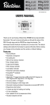
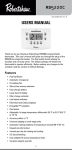
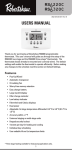
IMPORTANT SAFETY INFORMATION
Recycling Thermostat
WARNING:
This thermostat does not contain mercury. However, if this thermostat
is replacing a thermostat that contains mercury in a sealed tube, do
not place your old thermostat in the garbage. Contact your local waste
management authority for instructions regarding proper disposal of
the thermostat. If you have any questions, call Robertshaw technical
support at 1-800-445-8299.
Electrical Shock Hazard
352-00021-001 Rev B
Turn off power at the main power source by unscrewing
the fuse or switching the circuit breaker to the OFF
position before installing, removing or cleaning this
thermostat.
Digital Non-Programmable Thermostat
Installation and User Manual
Model: RS2110 and RS2210 Series
Fire and Electrical Shock Hazard
This device should be installed by a qualified service
technician with due regard for safety as improper
installation could result in a fire and electrical shock
hazard.
Fire and Electrical Shock Hazard
This is a 24 VAC low-voltage thermostat. Do not install on
voltages higher than 30 VAC.
INSTALLATION MANUAL
The information supplied here is for the mounting, wiring and switch
set up for the RS2110 and RS2210 thermostats. For programming and
operating functions, refer to the User Manual section.
Thank you for selecting our wall thermostat. Robertshaw® products are
manufactured to high quality standards and are designed to provide
years of service.
The RS2110 and RS2210 thermostats work with the following climate
control configurations:
• Heat Pump (No Auxiliary Heat)
• Heat Pump (With Auxiliary/Emergency Heat)
• Standard Heat and Cooling Systems
• Do not switch system to COOL if the temperature is below 50ºF
(10ºC). This can damage your cooling system and may cause
personal injury.
• Standard Heat Only Systems
• Millivolt Heat Only Systems - Floor or Wall Furnaces
• Standard Central Air Conditioning
• Gas or Oil Heat
• Electric Furnace
• Hydronic (Hot Water) Zone Heat-2 Wires
• Not to be Used With Split Transformer Systems
The RS2110 and RS2210 thermostats will NOT work with 3-Wire
Hydronic (Hot Water) Zone Heat 110/220 Volts. This thermostat
operates on 24 VAC power or battery power.
The thermostat will operate using 24 VAC or two AA batteries. When the
two AA batteries are installed the thermostat will continue to run if the
24 VAC fails.
To open the door to the battery compartment, gently pull down on the
sides. Install two AA batteries following the polarity as shown inside the
compartment. Close the door.
• Hammer
• Electric Drill and 3/16" Bit
• Two 1.5V (AA) Alkaline
Batteries (included)
CHECK THERMOSTAT OPERATION
Fan Operation
Electrical Shock Hazard
Turn off power at the main power source by unscrewing
the fuse or switching the circuit breaker to the OFF
position before installing, removing or cleaning this
thermostat.
• Do not install on voltages greater than 30 VAC.
1.
2.
Remove old thermostat: A standard heat/cool thermostat
consists of three basic parts:
When the batteries are low the thermostat will enter a low battery mode.
Low battery mode has two levels:
• Level 1 - The low battery icon will be
displayed. The thermostat will continue to
operate. Replace the batteries as soon as
possible.
• Level 2 - The low battery icon will flash. If 24
VAC is present the thermostat will continue
to operate if the batteries are discharged
or removed. If 24 VAC is not present the
thermostat is powered by batteries only and
THE SYSTEM WILL NOT OPERATE. Replace
batteries immediately.
Replace batteries if leaving thermostat unattended for more than
30 days.
3.
Move Fan switch to AUTO position. The blower should stop
immediately.
• New Improved Display makes viewing and setting the temperature
easier.
4.
Press the DOWN arrow to adjust the thermostat below room
temperature. The heating system should stop operating.
Cooling System
1.
Move System switch to select the COOL mode.
2.
Press the DOWN arrow to adjust thermostat setting below room
temperature. The blower should come on immediately on high
speed, followed by cold air circulation. The display should show
the snowflake icon pulsing.
3.
Press the UP arrow to adjust the temperature setting above
room temperature. The cooling system should stop operating.
If these tests are not successful, remove the thermostat body and
check for bent pins. Check all wiring connections.
If these tests are successful the thermostat is ready to operate using
the factory defaults. To change the configuration settings, refer to
Configuration in the User Manual section.
Installation of the thermostat is now complete. Remove the protective mylar over the screen and check that fresh batteries are properly
installed. Close all doors.
11
10
TWO YEAR LIMITED WARRANTY
Invensys Controls warrants to the original contractor installer, or to the
original consumer user, that each new Robertshaw thermostat will be
free from defects in materials and workmanship under normal use
and service for a period of two (2) years from the date of purchase
(the “Warranty Period”). If any Product fails within the applicable Warranty Period, Invensys Controls shall, at its option, repair or replace the
Product or credit the purchase price, provided the Product is returned
to Invensys Controls’ facility or designated agent within the Warranty
Period, with transportation or postage charges prepaid and proof of
the date of purchase, and the Product, upon examination by Invensys
Controls, is found not to conform to the Warranty. Cost of Product
removal, labor, or reinstallation of new Product are not covered under
this Warranty and are not the responsibility of Invensys Controls. Warranty on Products, parts and/or components sold, but not manufactured by Invensys Controls, shall be expressly limited to the warranty
terms of the manufacturer of such products, parts and/or components.
The above warranty does not apply to: i) batteries; ii) defects or damage that result from use of the Products in any manner other than
their normal and customary manner; iii) defects or damage that result
from use of the Products in any manner other than in accordance with
Invensys Controls’ recommendations and instructions; iv) defects or
damage which occur from misuse, alteration, accident, water, fire or
neglect; and/or v) defects due to abuse or damage such as burned
contacts, stripped threads, split castings, improper installation or
missing parts.
THE FOREGOING WARRANTY IS IN LIEU OF AND EXCLUDES ALL OTHER
WARRANTIES, WHETHER EXPRESS OR IMPLIED, INCLUDING THE
IMPLIED WARRANTIES OF MERCHANTABILITY, TITLE AND
FITNESS FOR A PARTICULAR PURPOSE. IN NO EVENT SHALL
INVENSYS CONTROLS BE LIABLE TO CONSUMER, CONTRACTOR OR
ANY THIRD PARTY FOR ANY CONSEQUENTIAL, INCIDENTAL, SPECIAL,
EXEMPLARY, OR PUNITIVE DAMAGES ARISING FROM OR RELATING TO
USE OF THE PRODUCT INCLUDING, BUT NOT LIMITED TO, LOSS OF
GOODWILL, LOSS OF PROFIT OR REVENUE, AND PROPERTY DAMAGE,
REGARDLESS WHETHER SUCH LOSS OR DAMAGE IS BASED IN CONTRACT, WARRANTY, TORT, NEGLIGENCE, STRICT LIABILITY, INDEMNITY,
PRODUCT LIABILITY, OR OTHERWISE AND EVEN IF INVENSYS CONTROLS HAS BEEN ADVISED OF THE POSSIBILITY OF SUCH DAMAGES.
REPAIR, REPLACEMENT, OR CREDIT OF THE PURCHASE PRICE, AS
PROVIDED HEREIN, SHALL CONSTITUTE THE SOLE REMEDIES WITH
RESPECT TO DEFECTS IN THE PRODUCTS. THE CONSUMER ASSUMES
ALL RISKS AND LIABILITY FOR INCIDENTAL AND CONSEQUENTIAL
DAMAGE RESULTING FROM INSTALLATION AND USE OF THE THERMOSTAT.
USER MANUAL
• Multi-Stage 2 Heat/1 Cool - RS2210 only. Operates on both
multi-stage gas/electric furnaces and heat pumps.
Figure 3
Terminal
voltage will damage the control and could cause an
electrical shock or fire hazard. Do not short out terminals
on gas valve or primary control to test.
Incorrect wiring will damage the thermostat and could
cause personal injury and/or property damage.
®
• Adjustable Temperature Differential maintains optimal customer
comfort.
• Worry-Free Memory Retention - RS2210 only. Maintains set point
and programmed parameters, even during power outages.
Pull the wires through the hole in the base. Connect wires
beneath terminal screws on base using the table under terminal
connections.
3.
Place base over the hole in wall and mark mounting hole
locations on wall using the base as a template.
4.
Move the base out of the way. Drill mounting holes.
5.
Fasten base loosely to wall, using two mounting screws. Place a
level against bottom of base, adjust until level, and then tighten
screws. Leveling is for appearance only and will not affect
thermostat operation. If you are using existing mounting holes,
or if holes drilled are too large and do not allow you to tighten
base snugly, use plastic screw anchors to secure the subbase.
6.
Push excess wire into wall and plug hole with a fire resistant
material (such as fiberglass insulation) to prevent drafts from
affecting thermostat operation.
System Switch Selection
Fan Switch - Set for continuous or automatic fan operation.
IMPORTANT: Please read the entire User Manual section before setting your thermostat.
DISPLAY MAP
The thermostat display will show information that is being used during
operation or programming. This illustration shows all of the display’s
possibilities with an explanation.
1
2
• O and B Terminals provides greater system flexibility.
3
• Zone System Compatible acts as a sensor within the system.
• Quick Wire Terminal Block uses sturdy wire clamps for fast and
easy installation - no wrapping around screws.
LCD Display
Down and
Up Arrows
- +
-
Reset Button
Door Latch
Fan Switch
System Switch
Figure 4
LCD Display - Shows Day, Temperature and other feature information.
Down and Up Arrows - Used to enter and navigate the configuration
menu and change the temperature settings.
12
STD
5
4
Figure 5
1.
Used with setpoint.
2.
Used for service reminders (e.g. CHECK HP).
3.
Used for current setpoint and some configuration data.
4.
HVAC mode and status. Icons blink when active. A is for Auto, 2
is for second stage and E is for emergency.
5.
Low battery indicator.
6.
Used for ambient temperature and configuration data (e.g. first
stage differential, F or C, etc.).
COMPRESSOR PROTECTION
The thermostat provides a 4 minute delay after shutting off the
heating or cooling system before it can be restarted. This feature will
prevent damage to your compressor caused by rapid cycling. Note
that this delay also applies to the heating system control. It does not
provide a delay when there are power outages.
13
24 VAC common
connection
24 VAC + connection
HP
GAS
Gas or Electric
The RS2110 thermostat is configured from the factory to operate a
heat/cool, fossil fuel (gas, oil, etc.), forced air system. It is configured
correctly for any system that DOES NOT require the thermostat to
energize the fan on a call for heat.
The RS2210 is configured at the factory to operate an electric heat or
heat-pump system that requires the thermostat to turn on the fan on
a call for heat. Locate the ELEC/GAS switch on the back of the thermostat (see “Figure 2 Electric/Gas Switch (Fan Option)”) and switch it
to the ELEC position. This will allow the thermostat to energize the fan
immediately on a call for heat.
Press the RESET button to accept a change in the switch option.
If your system is not a heat pump system, refer to the Configuration
section in this manual. The RS2210 thermostat must be changed to a
STD type system.
If you are unsure if the heating/cooling system requires the thermostat to control the fan, contact a qualified heating and air conditioning
service person.
For input of 24 VAC common side of
transformer. If 24 VAC is not present
the thermostat is powered by batteries only and THE SYSTEM WILL NOT
OPERATE.
For input of 24 VAC hot side of
transformer runs heating and cooling
system.
O
Energizes for heat pump cool reversing valve.
B
Energizes for heat pump heat reversing valve.
G
Figure 2 Electric/Gas Switch (Fan Option)
Equipment to
Connect
Y1*
E/W1*
Indoor fan connection
Energizes with Y1 and Y2.
Energizes with W1 and W2 if the
ELEC/GAS switch is set to electric.
Energizes when fan is switched to On.
First stage
Energizes on a call for first stage of
compressor con- cooling.
nection
Energizes on a call for first stage of
heating when configured as a HP.
First stage heat/
emergency heat
connection
Energizes on a call for first stage
of heating when configured as a
Non-Heat Pump. For Heat Pump
configuration, will energize for emergency heat.
W2
Second stage
heat connection
L
24 VAC compressor fault
output
Refer to the equipment manufacturer’s instructions for specific system
wiring information. You can configure the thermostat for use with a
Heat Pump Type 1, single stage compressor system. This thermostat
is designed to operate a single transformer system. If you have a two
transformer system, cut and tape off one transformer. If transformer
safety circuits are in only one of the systems, remove the transformer
of the system with no safety circuits. If required, replace the remaining transformer with a 75 VA Class II transformer. After disconnecting
one transformer, the two commons must be jumpered together.
Use the terminal output information below to help you wire the thermostat properly for your system.
Single Stage Heat and Cool: RS2110
A. Typical wiring diagram for single transformer standard system.
System selector switch must be set to STD.
NOTE: “Battery Operation Only” if 24 VAC common not present, other-
C
POWER FAILURE
Whenever the main power is interrupted or fails, the back-up battery
power will maintain the current settings. The heating and cooling
systems will not function. In the event of a power outage and dead
batteries, the settings will revert to default settings when power is
resumed. You must reprogram your settings.
FILTER MONITOR
The thermostat counts the number of hours your system’s filter has
been in use. To maximize your system’s performance and energy
efficiency, change or clean your filter regularly. When the total system
run time for heat and cool reaches 400 hours, the filter change indicator (Check FLtr) will flash as a reminder to check your system’s filter.
Press and hold the UP and DOWN arrows together until Check FLtr
no longer displays. This will reset the filter monitor to zero.
14
R
O
B
G
24 VAC
Supply
Y1 W1
Fan Relay
O
B
-
Figure 6
CONFIGURATION
The RESET button can be pressed with a paper clip to reset the
thermostat back to the factory defaults as shown in the Configuration
Menu Options table.
The Configuration Menu allows you to set certain thermostat operating
characteristics for your system or personal requirements. Set System
switch to OFF, then simultaneously press the UP and DOWN arrows
for three seconds to enter the Configuration Menu which summarizes
the options available. The display will show the first item in the Configuration Menu Options table. An explanation of each option is listed
after the table. Press the DOWN arrow to change to the next menu
item. To change the setting, press the UP arrow. When the maximum
setting is reached, the selections will return to the lowest selection. To
exit the menu and return to the program operation, press the DOWN
arrow until the main display appears. If no buttons are pressed within
fifteen seconds, the thermostat will revert to normal operation.
G
Heat Active
Reversing
Valve
Cool Active
Reversing
Valve
E. Typical wiring diagram for single transformer heat pump systems.
R O
C
24 VAC
Supply
Y1 W1
24 VAC
Common
(Battery
Operation
Only if not
present)
Compressor
Contactor
Fan Relay
G Y1 E/W1 W2 L System
B
Reversing
Valve
Energized in
Heat, Off,
Emergency
Mode
Reversing
Valve
Energized
in Cool
Mode
Default
Temperature Scale F/C
F
First Stage Differential
1°F (0.5°C)
RS2210 only - Second Stage Differential
2°F (1.1°C)
Off Set
0
RS2210 only - DLY 2
20
RS2210 only - System Type
HP
Temperature Scale - Select Fahrenheit or Celsius.
First Stage Differential - When the room temperature approaches the
set temperature the differential is the amount of overshoot allowed
before the thermostat calls for heating/cooling.
Second Stage Differential - Used for RS2210 only, same as First Stage
Differential but controls a second stage system.
Offset - Use this to change ambient temperature readings up or down.
DLY2 - Used for RS2210 only, is the second stage delay time.
HP - Used for selecting the system type on the RS2210. Select HP for
heat pump. Select STD1 for one stage heating non-heat pump. Select
STD2 for two stage heating non-heat pump.
Familiarize yourself with these manual settings, so that you can easily
modify your settings as your comfort needs change. The example
below demonstrates the manual settings method.
NOTE: The temperature can be set in increments of 1ºF (1ºC).The heat
setpoint cannot be set higher than the cool setpoint, and the
cool setpoint cannot be set lower than the heat setpoint. If the
system selector is in Heat mode, the heat operating mode will
be set. After 15 seconds without a button press, the thermostat will return to Normal Display mode.
Emergency
Heat Relay
Fan Relay
= Monitor
Switch
Compressor
Fault Output
(24 VAC) from
Heat Pump
24 VAC
120
VAC
Hot
Neutral
Two Stage Heat Single Stage Cool: RS2210
F. Typical wiring diagram for single transformer heat pump only.
C. Wiring diagram for single transformer standard system. System
selector in configuration menu must be set to STD2 or STD1
(single stage only).
C R O
NOTE: “Battery Operation Only” if 24 VAC common not present, otherwise “Battery Backup”.
C
R
O
B
G
Y1 E/W1
24 VAC
Common
(Battery
Operation
Only if not
present)
Fan Relay
L
Reversing
Valve Energized in Cool
Mode
Y1 E/W1 W2
G
Compressor
Contactor
Stage 1
Emergency
Heat
Fan Relay
L
Heat Relay
Stage 2
Second Stage
Heat (if STD2
selected)
Compressor
Contactor
24 VAC
Supply
W2
B
Reversing Valve
Energized in
Heat, Off,
Emergency
Mode
Compressor
Fault Output
(24 VAC) from
Heat Pump
24 VAC
120
VAC
Hot
Neutral
Transformer (Class II Current Limited)
First Stage
Heat
D. Wiring diagram for single transformer heat pump system. System
selector in configuration menu must be set to HP.
NOTE: “Battery Operation Only” if 24 VAC common not present, otherwise “Battery Backup”.
C
R
O
24 VAC
Common
(Battery
Operation
Only if not
present)
B
G
Heat Active
Reversing
Valve
Cool Active
Reversing
Valve
Y1 E/W1
L
Second
Stage or
Auxiliary Heat
Compressor
Contactor
Fan Relay
W2
Emergency
Heat
Compressor
Fault Output
(24 VAC) from
Heat Pump
8
Item
Auxiliary
Heat Relay
Compressor
Contactor
Transformer (Class II Current Limited)
7
When the batteries become weak, a flashing battery symbol will
appear on the screen. When this symbol occurs, install two new AA
batteries. You have approximately one minute to change the batteries
and keep the thermostat’s program settings. Once the batteries have
become too weak to ensure proper operation, your system will be
turned off, and the display will be blank if battery powered.
CAUTION: When the battery symbol flashes the batteries are weak. If
they are not replaced the display will fade. When the batteries are dead the display will be blank. There will be no
temperature control and settings are not saved.
NOTE: If you plan to be away from the premises over 30 days, we
recommend that you replace the old batteries with new alkaline batteries prior to leaving.
15
24 VAC
Common
(Battery
Operation
Only if not
present)
24 VAC
Supply
First Stage
Heat
R
24 VAC
Supply
Compressor
Contactor
24 VAC Common
(Battery Operation
Only if not present)
AUTO CUT-OFF
Consult with your installer to determine if your system is a heat pump
with an emergency heat system installed. If you have an emergency
heat system you can activate it in HEAT mode by pressing the UP and
DOWN arrows together. The display will show an E by the flame icon
when the thermostat is in system HEAT mode.
The main heating system will not receive a call to turn on. This will
allow maintenance to take place on the main heat system. To turn off
the emergency system, press the UP and DOWN arrows together. The
E will no longer be displayed.
C
wise “Battery Backup”.
Configuration Menu Options
- +
wise “Battery Backup”.
For input of fault signal from a
compressor.
WIRING DIAGRAMS
Heat Pump Terminal Outputs
6
+
NOTE: “Battery Operation Only” if 24 VAC common not present, other-
Energizes on a call for second stage
heating.
Replace the cover by inserting the bottom tab on the thermostat body
into the slot at the bottom of the wallplate. Move the cover to meet
the top of the wallplate. Press the top of the body to snap it into the
wallplate.
CAUTION: Do not force the thermostat body onto the wallplate. Terminal pins inside the thermostat may become damaged.
*This thermostat can be used as a heat only or cool only thermostat.
Therefore, it is not always necessary to use both W1 and Y1.
BATTERY WARNING
Your thermostat will automatically shut down in Heat mode if the room
temperature rises above 95ºF (35ºC). It will shut down in Cool mode if
the room temperature drops below 45ºF (7ºC).
Note that if your system has malfunctioned and no longer responds to
thermostat controls, the Auto Cut-Off will not work.
B. Typical wiring diagram for single transformer heat pump system.
System selector switch must be set to HP.
Description
Two Stage Model RS2210 (Additional Terminals)
This thermostat can be set between 45ºF and 90ºF (7ºC and 32ºC).
However, it will display room temperatures from 30ºF to 99ºF (0ºC and
37ºC).
NOTE: If the thermostat measures a temperature over 99ºF (37ºC), HI
will be displayed on the LCD. If the temperature is below 32ºF
(0ºC), LO will be displayed on the LCD.
EMERGENCY HEAT - RS2210 WITH HEAT PUMP
6
C
R
ELEC
Description
One Stage Model RS2110
Heat Pump or Non-Heat Pump (RS2110C only)
TEMPERATURE RANGE
Battery Compartment - Open with finger from sides. Install two AA
1.5V batteries.
Reset Button - Press to return to factory default.
Door Latch - Press gently on door to open/close.
System Switch - Select Cool/Off/Heat.
This section will describe the features and how to set up the RS2110
and RS2210 thermostats. Installation is described in detail in the
Installation Manual section.
Equipment to
Connect
5
• Automatic Compressor Short Cycle Protection reduces wear and
tear of HVAC equipment with this system safeguard.
Battery
Compartment
Figure 1 Thermostat Base
Remove the packing material from the thermostat. Push in on
the tab at the bottom. Gently pull the cover straight off the base.
Forcing or prying on the thermostat will cause damage to the
unit.
• Filter Monitor provides notice when filters need changing.
+
Terminals
CAUTION: Be certain all power is off to the system.
2.
Terminal
Thermostat Terminals
4
FEATURES AND BENEFITS
For a RS2210 system, adjust temperature setting to 3˚F/3˚C
above room temperature. If your system configuration is set for
auxiliary heat, the auxiliary heat system should begin to operate.
A 2 will appear by the flame icon.
When the thermostat is configured for heat pump, the thermostat will
always power the circulator fan on a call for heat in the Heat mode.
The ELEC/GAS switch for the 2 stage RS2210 model must be set to
match the type of auxiliary heat your system uses for proper operation
in the Emergency mode.
All wiring diagrams are for typical systems only. Refer to equipment
manufacturer’s instructions for specific system wiring information.
Mounting Holes
WARNING: Do not use on circuits exceeding specified voltage. Higher
3
Move Fan switch to ON position. The blower should begin to
operate.
3.
Install new thermostat using the following procedures.
c. The switching subbase or adapter plate - remove by
unscrewing the mounting screws that hold it on the wall.
Turn on power to system.
-
7.
b. The base - remove by loosening all screws.
2.
Press the UP arrow to adjust thermostat setting to 1˚F/1˚C above
room temperature. The heating system should begin to operate.
The display should show the flame icon in motion.
Disconnect the wires from the old thermostat one at a time. DO
NOT LET WIRES FALL BACK INTO THE WALL.
a. The cover - may be either a snap-on or hinge type.
1.
2.
6.
Shut off electricity at the main fuse box until installation is
complete. Ensure that electrical power is disconnected.
Thank you for selecting our wall thermostat. Robertshaw products
are manufactured to high quality standards and are designed to
provide years of service.
Move System switch to HEAT mode. If the heating system has a
standing pilot, be sure to light it.
Label each wire to identify which terminal it was connected to.
• Do not install on outside walls or in direct sunlight.
If your system does not have a G terminal connection, skip to Heating
System.
1.
Identify each wire attached to the old thermostat.
5.
WARNING:
• Use this thermostat only as described in this manual.
• The batteries must be replaced at least every 18-24 months to
assure proper operation. The thermostat will display a flashing low
battery when it is time to replace the batteries. The manufacturer
recommends inserting fresh batteries before leaving for an
extended period.
4.
1.
Replacing Existing Thermostat
• Before removing wires from old thermostat, label each wire with
the terminal designation it was removed from.
• This thermostat is equipped with automatic compressor protection
to prevent damage due to short cycling or extended power
outages. The short cycle protection provides a 4 minute delay
between heating or cooling cycles to prevent the compressor from
being damaged.
Remove the front cover of the old thermostat. With wires still
attached, remove wallplate from the wall. If the old thermostat
has a wall mounting plate, remove the thermostat and the wall
mounting plate as an assembly.
Attach Thermostat Base to Wall
IMPORTANT:
Heating System
19
• Small Phillips Screwdriver
2
INSTALL BATTERIES
- +
• Slotted Screwdriver(s)
• All wiring must conform to local and national building and
electrical codes and ordinances.
1
+
What you need:
This thermostat includes two #8 slotted screws and two wall anchors
for mounting. To install your thermostat, you should have the following
tools and materials.
• Do not connect ground to any terminal in this unit.
• Read all the information in this manual before installing this
thermostat.
• Two Stage Heat, One Stage Cool - RS2210
MOUNTING
• Do not short (jumper) across terminals on the gas valve or at the
system control to test installation. This will damage the thermostat
and void the warranty.
CAUTION:
• One Stage Heat/Cool - RS2110
3.
TROUBLESHOOTING
OPERATION
System Selector Switch
system
cool
9
The System Selector switch on the front of the
thermostat determines the operating mode of the
thermostat. You may select COOL, OFF, or HEAT.
off heat
NOTE: Anytime you install or remove the thermostat
from the wallplate, slide the System Selector to the OFF position to prevent the possibility of a rapid system on-off.
Fan Switch
fan
The Fan switch should normally be set in the AUTO
position. The fan will be turned on along with normal
operation of your system. In a normal gas or oil
furnace, the fan will be turned on by your furnace
on
auto
after its warm-up delay. For electric heat, air
conditioning, and heat pump operation, the fan will turn on with the
system. To run the fan continuously, slide the Fan switch to the
ON position.
Problem
Solution
Scrambled or double
display (numbers over
numbers).
Remove clear mylar sticker.
No display.
Check connections and batteries.
Press Reset once with a small pin and
hold for two seconds then reprogram.
Entire display dims.
Replace batteries.
Auto/Fan does not turn
On.
There may be as much as four minute
delay before the heat or cool system
turns on. Wait and check. (Compressor
protection delay).
Check your circuit breakers and switches
to ensure there is power to the system.
Replace batteries.
Make sure your furnace blower door is
closed properly.
Check the position of the furnace or Heat
Pump selector switches.
Erratic display.
Press RESET once with a small pin and
hold for two seconds then reprogram.
Thermostat reads E1.
Temperature sensor defective. Replace
unit.
Thermostat reads E2.
System switch in wrong position. Move
system switch to correct position.
If you experience any other problems, contact Technical Support at:
www.invensyscontrols.com or (800) 445-8299.
Changing Settings
Start with a normal running display.
1.
Select Heating with the system switch.
2.
Use the UP and DOWN arrows to select the temperature for
heating.
3.
Switch between HEAT and COOL. Repeat step 2 to select the
temperature for cooling.
16
17
18
Some states do not allow the exclusion or limitation of incidental or
consequential damages, or allow limitations on how long an implied
warranty lasts, so the above limitations or exclusions may not apply
to you. This Warranty gives you specific legal rights, and you may also
have other rights which vary from state to state.
For Warranty returns, send the thermostat, shipping prepaid and proof
of date of purchase to:
Invensys Controls
Warranty Claims Department
515 S. Promenade Ave.
Corona, CA 92879-1736
In Canada:
Invensys Controls
Warranty Claims Department
3505 Laird Rd. Unit #14
Mississauga, Ontario L5L 5Y7 Canada
191 E. North Avenue
Carol Stream, Illinois 60188 USA
www.invensyscontrols.com
©2012 Invensys Controls 7/12
20
21
22
23
24
25
26
352-00021-001 Rev B
27
Los termostatos RS2110 y RS2210 NO funcionan con calefacción de
zona hidrónica (agua caliente) con 3 conectores de 110/220 voltios.
Este termostato funciona con alimentación de 24 VCA o con pilas.
352-00021-001 Rev B
INFORMACIÓN DE SEGURIDAD IMPORTANTE
• Las pilas deben cambiarse por lo menos cada 18-24 meses para
garantizar el correcto funcionamiento. El termostato mostrará
el icono de pila baja destellante cuando llegue el momento de
cambiar las pilas. El fabricante recomienda insertar pilas nuevas
antes de ausentarse por un período prolongado.
ADVERTENCIA:
Reciclado de termostatos
Peligro de choque eléctrico
Termostato digital no programable
Desconecte el suministro eléctrico principal desatornillando
el fusible o moviendo la llave del disyuntor a la posición OFF
(apagado) antes de instalar, retirar o limpiar este termostato.
Manual de instalación y manual del usuario
Modelo: series RS2110 y RS2210
Peligro de incendio y choque eléctrico
Este dispositivo debe ser instalado por un técnico
calificado con las debidas precauciones de seguridad, ya
que una instalación inadecuada puede generar peligro de
incendio y choque eléctrico.
Peligro de incendio y choque eléctrico
MANUAL DE INSTALACIÓN
La información proporcionada en este manual se refiere al montaje,
el cableado y la configuración del conmutador para los termostatos
RS2110 y RS2210. Para información sobre las funciones de programación y operación, diríjase a la sección Manual del Usuario.
Gracias por elegir nuestro termostato de pared. Los productos de
Robertshaw® son fabricados con altos estándares de calidad y están
diseñados para proporcionar años de servicio.
Los termostatos RS2110 y RS2210 operan con las siguientes configuraciones de control de clima:
• Bomba de calor (sin calor auxiliar)
• Bomba de calor (con calor auxiliar/de emergencia)
• Sistemas estándar de calor y frío
Este es un termostato de bajo voltaje 24 VCA. No instale
con voltaje superior a 30 VCA.
• No conmute el sistema a FRÍO si la temperatura es inferior a 50ºF
(10ºC). Esto puede dañar el sistema de refrigeración y provocar
lesiones personales.
• No deben puentearse los terminales de la válvula de gas ni
el control del sistema para probar la instalación. Esa práctica
perjudicará el termostato y causará la nulidad de la garantía.
• No conecte a tierra ninguno de los terminales de esta unidad.
Identifique cada cable conectado al termostato viejo.
Lo que usted necesita:
Este termostato incluye dos tornillos ranurados Nº 8 y dos anclajes de
pared para su montaje. Para instalar su termostato deberá tener las
siguientes herramientas y materiales.
5.
Rotule cada cable para identificar a qué terminal estaba
conectado.
6.
Desconecte los cables del viejo termostato uno por vez. NO
DEJE QUE LOS CONDUCTORES SE INTRODUZCAN EN LA PARED.
• Pequeño destornillador Philips
7.
• Martillo
• Taladro eléctrico y broca de 3/16”
ADVERTENCIA: No use en circuitos que superen la tensión espe-
Cambio del termostato existente
ADVERTENCIA:
Peligro de choque eléctrico
Fije la base del termostato a la pared
Desconecte el suministro eléctrico principal
desatornillando el fusible o moviendo la llave del
disyuntor a la posición OFF (apagado) antes de instalar,
retirar o limpiar este termostato.
1.
• Lea toda la información que aparece en este manual antes de
instalar el termostato.
• Antes de retirar los conectores del termostato viejo, rotule cada
cable con la designación del terminal del que lo desconectó.
• Este termostato está configurado con protección automática del
compresor para prevenir daños por ciclos de corta duración o
cortes prolongados de suministro de energía. La protección de
ciclo corto ofrece un retardo de 4 minutos entre los ciclos de
calefacción o refrigeración para evitar daños en el compresor.
• No instale con voltaje superior a 30 VCA.
• Calefacción a gas o aceite
• Caldera eléctrica
• Calefacción de zona hidrónica (agua caliente) - 2 conductores
6.
Empuje el excedente de conectores dentro de la pared y tapone
el orificio con material resistente al fuego (como aislación con
fibra de vidrio) para evitar corrientes de aire que puedan afectar
el funcionamiento del termostato.
Orificios de montaje
Terminales
Figura 1 Base del termostato
Llave selectora
Bomba de calor o sin bomba de calor
(sólo el modelo RS2110)
Retire el material de embalaje del termostato. Empuje sobre la
solapa de la base. Suavemente, tire de la base para separarla
de la tapa. Forzar o hacer palanca sobre el termostato puede
ocasionar daños a la unidad.
Desconecte la electricidad desde la caja principal de fusibles
hasta que la instalación esté terminada. Asegúrese de que esté
desconectado el suministro de energía eléctrica.
El termostato RS2110 está configurado de fábrica para operar un
sistema de calefacción/refrigeración (gas, fuel oil, etc.) o aire forzado.
Está configurado correctamente para cualquier sistema que NO requiere que el termostato energice el ventilador cuando haya demanda de
la calefacción.
El modelo RS2210 está configurado de fábrica para operar un sistema
de calefacción eléctrica o con bomba de calor que requiere que el
termostato active el ventilador cuando haya demanda de calefacción. Ubique la llave ELEC/GAS en la parte posterior del termostato
(ver “Figura 2 llave Electric/Gas (opción ventilador)” y coloque en la
posición ELEC. Esto permitirá que el termostato energice el ventilador
inmediatamente cuando haya demanda de calefacción.
Presione el botón de reprogramación para aceptar un cambio en la
llave selectora.
Si su sistema no opera con bomba de calor, remítase a la sección
Configuración de este manual. El termostato RS2210 debe conmutarse a un sistema tipo STD.
Si usted no está seguro si el sistema de calefacción / refrigeración
requiere que el termostato controle al ventilador, póngase en contacto
con un técnico calificado en calefacción o aire acondicionado.
Cuando el termostato esté configurado para bomba de calor, siempre
activará el ventilador de circulación cuando haya demanda de
calefacción en el modo HEAT. Para operar correctamente en el modo
Emergencia, la llave ELEC/GAS para el modelo RS2210 de dos etapas
debe estar en una posición que se corresponda con el tipo de calor
auxiliar que usa su sistema.
Todos los diagramas de cableado corresponden exclusivamente a
sistemas típicos. Consulte las instrucciones del fabricante del equipo
para ver la información específica sobre el cableado del sistema.
STD
ADVERTENCIA: Asegúrese de que el sistema esté desconectado de
2.
Jale los conectores a través del orificio de la base. Conecte
los conectores debajo de los tornillos de los terminales de la
base usando la tabla que aparece debajo de las conexiones del
terminal.
3.
Coloque la base sobre el orificio de la pared y marque la
ubicación de los orificios de montaje sobre la pared usando la
base como plantilla.
ELEC
Terminales de termostato
Terminal
Equipo que se
debe conectar
C
Conexión común
de 24 VAC
Terminal
Descripción
Modelo RS2110 de una etapa
R
24 VAC + conexión
Para entrada de 24 VAC lado común
del transformador. Si el sistema no
está conectado a la red eléctrica de
24 VAC, el termostato está alimentado
por las pilas exclusivamente y EL
SISTEMA NO FUNCIONARÁ
Para entrada de 24 VAC el lado
caliente del transformador opera el
sistema de calefacción y refrigeración
O
Energiza para válvula inversora en
modo frío de bomba de calor
B
Energiza para válvula inversora en
modo calor de bomba de calor
G
Y1*
E/W1*
Conexión
ventilador
interiores
Energiza con Y1 y Y2.
Energiza con W1 y W2 si la llave Elec/
Gas se coloca en la posición Electric.
Energiza cuando el ventilador está en
On (prendido).
Conexión de
compresor
primera etapa
Energiza con demanda de primera
etapa de refrigeración.
Energiza con demanda de primera
etapa de calefacción y está configurado como una HP.
Conexión
primera etapa
de calefacción/
calefacción de
emergencia
Energiza con demanda de primera
etapa de calefacción y no está configurado como HP. Para configuración
como bomba de calor, energizará
para calefacción de emergencia.
*Este termostato puede usarse como termostato para calefacción solamente y refrigeración solamente. Por lo tanto, no siempre es necesario
usar W1 y Y1 a la vez.
HP
la energía.
• No instale en paredes exteriores ni al sol.
1.
Asegure la base a la pared usando dos tornillos de montaje sin
terminar de atornillar. Coloque un nivel sobre la parte inferior
de la base, regule hasta que esté nivelado y después ajuste
los tornillos. La nivelación sólo se realiza por razones estéticas
y no afecta el funcionamiento del termostato. Si usted está
usando los orificios de montaje existentes, o si los orificios
son demasiado grandes y no puede ajustar bien la base, use
insertos de plástico para asegurar la sub-base.
Instale el nuevo termostato siguiendo el procedimiento que se
indica a continuación.
cificada. Una tensión mayor dañará el control y puede
provocar un choque eléctrico o un incendio. No puentee
los terminales de la válvula de gas ni del control primario
para probarlos. Un cableado incorrecto dañará el termostato y podría provocar lesiones personales y/o daños
materiales.
• Dos pilas alcalinas de
1.5 V (AA) (incluidas)
IMPORTANTE:
• Aire acondicionado central estándar
Retire la tapa delantera del termostato viejo. Con los conectores
todavía conectados, retire de la pared la placa de pared. Si el
termostato viejo tiene una placa de montaje para la pared, retire
el termostato y la placa de montaje de la pared en conjunto.
• Destornillador(es) para
tornillos con ranura
ADVERTENCIA:
5.
c. La sub-base de conmutación o placa de adaptación, que
se retira aflojando los tornillos de montaje que lo sostienen
sobre la pared.
4.
• Dos etapas calor, una etapa frío - RS2210
Retire la base de la pared. Realice los orificios para el montaje.
b. La base, que se retira para aflojar todos los tornillos.
MONTAJE
• Todas las conexiones de cableado deben cumplir con las normas
y disposiciones locales y nacionales que rigen en materia de
construcción y electricidad.
4.
a. La tapa, que puede ser del tipo que se engancha o con
bisagras.
3.
• Use este termostato sólo según las indicaciones que aparecen en
este manual.
• Sistemas Millivolt de calor únicamente - Calderas de piso o de
pared
Retire el antiguo termostato: Un termostato estándar para
calefacción/refrigeración incluye tres partes básicas:
Este termostato no contiene mercurio. Sin embargo, si instala este
termostato para reemplazar un equipo que contiene mercurio en tubo
sellado, no deseche su viejo termostato con los residuos domiciliarios.
Comuníquese con la autoridad local de manejo de los residuos para
recibir instrucciones sobre la correcta disposición del termostato.
Si tiene alguna pregunta llame al soporte técnico de Robertshaw al
1-800-445-8299.
• Calor/frío una etapa - RS2110
• Sistemas estándar de calor únicamente
2.
GAS
Equipo que se
debe conectar
Descripción
Modelo RS2210 de dos etapas (terminales adicionales)
W2
Conexión
segunda etapa
de calefacción
Energiza con demanda de segunda
etapa de calefacción.
L
24 VAC salida de
falla
de compresor
Para entrada de señal de falla de un
compresor.
Calefacción y refrigeración de una etapa: RS2110
A. Diagrama típico de cableado para sistemas estándar de un solo
transformador. La llave selectora del sistema debe configurarse
en STD.
NOTA: “Operación a batería exclusivamente” si no se tiene conexión
común de 24 VCA, caso contrario “Respaldo de batería”.
Vuelva a colocar la tapa insertando la solapa de la base del cuerpo
del termostato en la ranura de la parte inferior de la placa de la pared.
Mueva la tapa para hallar la parte superior de la placa de la pared.
Presione la parte superior del cuerpo para que trabe en la placa de la
pared.
ADVERTENCIA: No fuerce el cuerpo del termostato sobre la placa de
la pared. Se pueden dañar las clavijas del terminal del
interior del termostato.
DIAGRAMAS DE CABLEADO
Terminales de salida para la bomba de calor
Consulte las instrucciones del fabricante del equipo para ver la información específica sobre el cableado del sistema. Puede configurar
el termostato para usarlo con un sistema compresor de una etapa,
Bomba de Calor Tipo 1. Este termostato ha sido diseñado para operar
en un sistema con un solo transformador. Si tiene un sistema con dos
transformadores, corte y ponga cinta aisladora en la conexión de un
transformador. Si los circuitos de seguridad de los transformadores
se encuentran en sólo uno de los sistemas, retire el transformador
del sistema que no tiene circuitos de seguridad. Si es necesario,
reemplace el otro transformador por un transformador de 75 VA Clase
II. Después de desconectar un transformador, se deben puentear los
dos comunes entre sí.
Consulte la información sobre terminales de salida que encontrará
más abajo como ayuda para conectar el termostato de la forma correcta para su sistema.
C
R
O
B
G
Alimentación
de 24 VCA
Y1 W1
Contactor del
compresor
Común de 24 VCA
(Operación a batería sólo si
no se tiene esta conexión)
Relé del
ventilador
Calefacción
de primera
etapa
B. Diagrama típico de cableado para sistemas de bomba de calor
de un solo transformador. La llave selectora del sistema debe
configurarse en HP.
NOTA: “Operación a batería exclusivamente” si no se tiene esta conexión común de 24 VCA, caso contrario “Respaldo de batería”.
C
R
O
Alimentación
de 24 VCA
Común de 24
VCA (Operación
a batería sólo si
no se tiene esta
conexión)
B
G
Válvula inversora activa en
calor
Válvula
inversora
activa en
frío
Y1 W1
Contactor del
compresor
Relé del
ventilador
Gas o electricidad
Figura 2 Llave electricidad/gas (opción ventilador)
• No apto para uso con sistemas de transformador de separación
1
2
Dos etapas calor / una etapa frío: RS2210
C. Diagrama de cableado para sistema estándar de un solo
transformador. El selector del sistema en el menú de
configuración debe estar en STD2 o STD1 (una etapa solamente).
F. Diagrama típico de cableado para bombas de calor de un solo
transformador.
C R O
NOTA: “Operación a batería exclusivamente” si no se tiene conexión
R
O
B
G
Y1 E/W1
Común de 24 VCA
(Operación a
batería sólo si no
se tiene esta
conexión)
L
Calor de segunda
etapa (si se
selecciona STD2)
Contactor del
compresor
Alimentación
de 24 VCA
W2
Válvula inversora activa en
calor
Alimentación
de 24 VCA
Válvula
inversora
activa en
frío
Común de 24
VCA
(Operación a
batería sólo si
no se tiene esta
conexión)
G
Y1 E/W1
W2
Calefacción de
emergencia
Relé del
ventilador
L
Segunda
etapa o calor
auxiliar
Contactor del
compresor
R
O
Alimentación
de 24 VCA
Común de
24 VCA
(Operación
a batería
sólo si no
se tiene
esta
conexión)
Válvula
inversora
energizada
en modo
frío
Contactor
del compresor
Relé del
ventilador
Neutral
- +
-
Figura 3
Salida en falla
del compresor
(24 VCA) de la
bomba de calor
120
VCA
Calor
Neutral
11
LOCALIZADOR DE FALLAS
Para cambiar los valores
Empiece con un visor en función normal.
Problema
Solución
Use las flechas ARRIBA y ABAJO para elegir la temperatura de
calefacción.
Visor doble o distorsionado (números sobre
números)
Retire la etiqueta de Mylar.
Conmute entre CALOR y FRÍO. Repita el paso 2 para elegir la
temperatura de refrigeración.
No aparece el visor.
Verifique las pilas y las conexiones de
las pilas.
3.
OPERACIÓN
Interruptor del Selector del Sistema
Mantenga apretado el botón Reset con
un pequeño perno durante 2 segundos y
después reprograme.
sistema
El interruptor del Selector del Sistema que
aparece en la parte del frente del termostato
determina el modo de operación del mismo.
frío apagado calor
Usted podrá seleccionar COOL, OFF o HEAT
[FRÍO , APAGADO o CALOR].
NOTA: Cada vez que instale o retire el termostato de la placa de
pared, coloque el Selector de Sistema en la posición OFF
(apagado) para evitar un rápido ENCENDIDO – APAGADO del
sistema.
Se oscurece todo el
visor.
Cambie las pilas.
El ventilador automático no funciona.
Puede haber a lo sumo 4 minutos de
retardo antes de que el sistema para que
el sistema de calefacción o refrigeración
lo conecte. Espere y verifique. (Retardo
de protección del compresor).
Verifique los disyuntores e interruptores
del circuito para asegurarse de que el
sistema esté energizado.
Interruptor del ventilador
ventilador
El interruptor del ventilador deberá estar
normalmente en la posición AUTO. El
ventilador se encenderá durante la
encendido automático
operación normal de su sistema. En una
caldera normal de gas o gasoil, el ventilador se encenderá cuando
funcione la caldera después de período de retardo para calentamiento. En el caso de calefacción eléctrica, aire acondicionado y de
operación de una bomba de calor, el ventilador se encenderá con su
sistema. Para que el ventilador funcione continuamente, coloque el
interruptor del ventilador (Fan) en la posición ON (encendido).
Cambie las pilas.
Asegúrese que la puerta del ventilador de
la caldera esté cerrada.
Verifique la posición del interruptor de
selección de la caldera o bomba de calor.
Visor errático.
Mantenga apretado el botón Reset con
un pequeño perno durante 2 segundos y
después reprograme.
El termostato lee E1.
Sensor de temperatura fallado. Cambie
la unidad
El termostato lee E2.
El interruptor del sistema está en la
posición equivocada. Lleve la llave del
sistema a la posición correcta.
Si usted se encuentra con cualquier otro problema, póngase en contacto con Soporte Técnico en: www.invensyscontrols.com o llamando
al (800) 445-8299.
19
1.
Conecte la electricidad.
2.
Lleve la llave del ventilador a la posición ON. El ventilador debe
comenzar a funcionar.
3.
Lleve la llave del ventilador a la posición AUTO. El ventilador
debe detenerse de inmediato.
1.
2.
4.
10
2.
Si su sistema no tiene una conexión a la terminal G, pase a Sistema
de Calefacción.
3.
Transformador (Clase II corriente limitada)
Elija Calefacción con el interruptor del sistema.
CONTROL DE LA OPERACIÓN DEL TERMOSTATO
Operación del ventilador
Llave de
= monitoreo
del sistema
24 VCA
1.
• Nivel 2 El ícono de pila baja destella. Si el
sistema está conectado a la red eléctrica de
24 VCA, el termostato seguirá funcionando
si las pilas están descargadas o se las ha
quitado. Si el sistema no está
conectado a la red eléctrica de 24 VCA,
el termostato está alimentado por las
pilas exclusivamente y EL SISTEMA
NO FUNCIONARÁ. Cambie las pilas
inmediatamente.
Cambie las pilas si el termostato quedará sin atención durante más
de 30 días.
Sistema de calefacción
+
L
Relé de calor
auxiliar
Relé de
calor de
emergencia
120
VCA
Calor
Salida en
falla del
compresor
(24 VCA) de
la bomba de
calor
B G Y1 E/W1 W2
Válvula
inversora
energizada
en Calor,
Apagado
(Off), Modo
emergencia
Salida en falla
del compresor
(24 VCA) de la
bomba de calor
Estos termostatos funcionan con dos pilas AA o con corriente de
24 VCA. Cuando las dos pilas AA están instaladas, el termostato
seguirá funcionando si hay un corte de la corriente 24 VCA.
Para abrir la puerta del gabinete de las pilas, empuje suavemente
hacia abajo desde los costados. Coloque dos pilas AA siguiendo las indicaciones de polaridad que figuran en el interior del compartimiento.
Cierre la puerta.
E. Diagrama típico de cableado para sistemas de bombas de calor
de un solo transformador.
C
Relé de calor
Etapa 2
Calefacción de
emergencia
Cuando las pilas están bajas, el termostato empieza a funcionar en
modo pila baja.
El modo pila baja tiene dos niveles:
20
4
Sistema de refrigeración
1.
Mover la llave del Sistema para seleccionar el modo FRÍO.
2.
Presione la flecha DOWN (ABAJO) para configurar el termostato
por debajo de la temperatura ambiente. El ventilador debe
encenderse inmediatamente a alta velocidad, seguido de
circulación de aire frío. El visor debe mostrar el ícono del copo
de nieve pulsando.
• Nivel 1 Aparece en el visor el ícono de pila
baja. El termostato sigue funcionando. Cambie
las pilas lo antes posible.
INSTALACIÓN DE PILAS
ión común de 24 VCA, caso contrario “Respaldo de batería”.
B
Relé del
ventilador
L
Transformador (Clase II
Corriente limitada)
NOTA: “Operación a batería exclusivamente” si no se tiene la conex-
O
Contactor del
compresor
Etapa 1
Calefacción
de primera
etapa
Relé del
ventilador
R
Válvula
inversora
energizada
en modo frío
Y1 E/W1 W2
G
24 VCA
D. Diagrama de cableado para sistemas de bomba de calor de
un solo transformador. El selector del sistema en el menú de
configuración se debe fijar en HP.
C
B
Válvula inversora energizada
en Calor, Apagado (Off), Modo
emergencia
común de 24 VCA, caso contrario “Respaldo de batería”.
C
3
Lleve la llave del sistema al modo CALOR. Si el sistema de
calefacción tiene un piloto fijo, asegúrese de encenderlo.
Presione la flecha UP (ARRIBA) para ajustar la configuración del
termostato a 1˚F/1˚C sobre la temperatura ambiente. El sistema
de calefacción debe comenzar a funcionar. La pantalla debe
mostrar el ícono de la llama en movimiento.
Para un sistema RS2210, ajuste el valor de temperatura a
3˚F/3˚C sobre la temperatura ambiente. Si la configuración del
sistema está en calor auxiliar, el sistema de calor auxiliar debe
comenzar a operar. Aparecerá un 2 al lado del ícono de la llama.
Presione la flecha DOWN (ABAJO) para ajustar el termostato por
debajo de la temperatura ambiente. El sistema de calefacción
debe dejar de operar.
12
GARANTÍA LIMITADA POR DOS AÑOS
Invensys Controls garantiza al contratista instalador original o al usuario final original, que todo nuevo termostato Robertshaw estará libre
de defectos en los materiales y fabricación bajo condiciones normales
de uso y servicio por un período de dos (2) años a partir de la fecha
de compra (el “Período de Garantía”). Si alguno de los Productos falla
dentro del Período de Garantía aplicable, Invensys Controls, a su propia opción, reparará o reemplazará el Producto o acreditará el precio
de compra, siempre que el Producto sea devuelto a la sede de Invensys Controls o del agente designado dentro del Período de Garantía,
con los gastos de transporte o envío postal prepagos y prueba de la
fecha de compra, y que una vez que el Producto haya sido examinado
por Invensys Controls se haya verificado que no cumple con las condiciones garantizadas. Los costos de retiro del producto, de la mano
de obra o de la reinstalación del nuevo producto no están cubiertos
por esta Garantía y no son responsabilidad de Invensys Controls. La
Garantía de los Productos, las partes o los componentes vendidos
pero no fabricados por Invensys Controls se limitará expresamente a
los términos de garantía del fabricante de dichos productos, partes o
componentes.
La garantía que antecede no es aplicable a: i) pilas; ii) defectos o
daños originados en el uso de los Productos de una manera distinta
de la manera normal y habitual; iii) defectos o daños originados en
un uso de los Productos de una manera distinta de la indicada por las
recomendaciones e instrucciones de Invensys Controls; iv) defectos
o daños producidos en el uso indebido, alteración, accidente, agua,
fuego o negligencia; y/o v) defectos debidos al abuso o a daños
producidos por contactos quemados, roscas deterioradas, piezas
partidas, instalación incorrecta o partes faltantes.
LA GARANTÍA QUE ANTECEDE EXCLUYE A TODA OTRA GARANTÍA,
EXPRESA O IMPLÍCITA, INCLUYENDO LAS GARANTÍAS IMPLÍCITAS
DE APTITUD PARA COMERCIALIZACION, DE TÍTULO Y APTITUD PARA
DETERMINADAS APLICACIONES. EN NINGÚN CASO INVENSYS CONTROLS SERÁ RESPONSABLE ANTE LOS CONSUMIDORES, CONTRATISTAS O TERCEROS POR DAÑOS INDIRECTOS, INCIDENTALES, ESPECIALES, DAÑOS Y PERJUICIOS CON CARACTER EJEMPLAR O PUNITIVOS
RELACIONADOS CON EL USO DEL PRODUCTO, INCLUYENDO, EN
FORMA NO TAXATIVA: PÉRDIDA DE IMAGEN, LUCRO CESANTE Y DAÑO
A LA PROPIEDAD, INDEPENDIENTEMENTE DE SI DICHA PÉRDIDA O
DAÑO SE ORIGINA EN UNA RELACIÓN CONTRACTUAL, GARANTÍA,
ACTO ILÍCITO, NEGLIGENCIA, RESPONSABILIDAD ESTRICTA, INDEMNIZACIÓN, RESPONSABILIDAD DE PRODUCTO U OTROS, AÚN SI
INVENSYS CONTROLS HA SIDO NOTIFICADO SOBRE LA POSIBILIDAD
DE DICHOS DAÑOS.
21
3.
Presione la flecha UP (ARRIBA) para configurar la temperatura
por encima de la temperatura ambiente. El sistema de
refrigeración debe dejar de operar.
Si estas pruebas no funcionan, retire el cuerpo del termostato y
verifique si hay clavijas dobladas. Verifique todas las conexiones de
cableado.
Si estas pruebas funcionan bien, el termostato está listo para operar
usando los valores de fábrica. Para cambiar los valores de configuración, diríjase a Configuración en la sección Manual del Usuario.
La instalación del termostato está completa. Retire la etiqueta protectora de Mylar de la pantalla y verifique si las baterías nuevas están
correctamente instaladas. Cierre todas las puertas.
MANUAL DEL USUARIO
Gracias por elegir nuestro termostato de pared. Los productos
Robertshaw® se fabrican conforme a las más altas normas de
calidad y están diseñados para durar muchos años.
CARACTERÍSTICAS Y PRESTACIONES
• El modelo RS2210 de 2 etapas de calefacción y 1 etapa de
refrigeración funciona sólo con sistemas de etapa múltiple de
calefacción eléctrica o a gas y bombas de calor.
• Nuevo visor perfeccionado : facilita la visualización y la
programación de la temperatura.
• Diferencial ajustable de temperatura : mantiene el confort óptimo
del cliente.
• Retenedor de memoria Worry-Free : El modelo RS2210 sólo
mantiene los valores deseados y los parámetros programados, aún
durante el corte de energía eléctrica.
• Monitor del filtro : avisa cuando debe cambiarse el filtro.
• Protección automática del compresor para prevenir daños por
ciclos de corta duración : Este mecanismo de seguridad reduce
el desgaste del equipo HVAC.
13
5
6
7
• Terminales O y B : brindan mayor flexibilidad al sistema.
APAGADO AUTOMÁTICO
• Compatibilidad con el sistema zonal : actúa como un sensor
dentro del sistema.
En el modo Heat su termostato se apagará automáticamente si la
temperatura ambiente supera los 95 ºF (35 ºC). En el modo Cool se
apagará si la temperatura ambiente baja por debajo de los 45 ºF (7 ºC).
Tenga en cuenta que si su sistema ha tenido algún desperfecto y no
responde al control del termostato, no funcionará el Apagado Automático.
• Bloque terminal de conexión rápida : utiliza sólidas abrazaderas
de alambre para una instalación fácil y rápida, sin cableado tipo
manto.
1
2
3
Esta sección describe las características y programación de los
termostatos RS2110 y RS2210. La instalación se describe en detalle
en el Manual de Instalación.
El visor de LCD
6
5
4
Figura 5
1.
Flechas
arriba y
abajo
2.
+
Compartimiento
para la pilas
- +
-
Tecla de
reprogramación
Traba de
la puerta
Interruptor del
ventilador
Interruptor del
sistema
Figura 4
El visor de LCD muestra el día, la temperatura y otros datos de
prestaciones.
Flechas arriba y abajo - Se usan para ingresar y para navegar por el
menú de configuración y modificar los valores de temperatura.
Compartimiento para la pilas - Se abre con los dedos desde el
costado. Instale dos pilas AA de 1.5 V.
Tecla de reprogramación - Pulsar para volver a la programación de
fábrica.
Traba de la puerta - Presionar suavemente la puerta para abrir/cerrar.
Interruptor del sistema - Seleccionar Cool (frío)/Off (apagado)/Heat (calor).
Interruptor del ventilador - Programar para el funcionamiento continuo o automático del ventilador.
IMPORTANTE: Programar para el funcionamiento continuo o automático del ventilador.
MAPA DEL VISOR
El visor del termostato muestra la información en uso durante el
funcionamiento o la programación. El dibujo muestra las posibilidades
del visor y la explicación.
14
3.
4.
Utilizado con el valor deseado.
Utilizado para recordatorios de servicio (por ejemplo,
CONTROLAR HP).
Utilizado para los valores deseados actuales y algunos datos de
configuración.
Modo y estado de HVAC. Los iconos destellan cuando está
activo. A corresponde a automático, 2 es para la segunda etapa
y E es para emergencia.
5.
Indicador de pilas bajas.
6.
Utilizado para la temperatura ambiente y datos de configuración
(por ejemplo, diferencial de primera etapa, F o C, etc.).
PROTECCIÓN DEL COMPRESOR
El termostato proporciona un retardo de 4 minutos después de apagar
el sistema de calefacción o refrigeración antes de que pueda ser
reiniciado. Esta característica evita daños a su compresor debidos
de un ciclo rápido de apagado-encendido. Tenga en cuenta que este
retardo también se aplica al control del sistema de calefacción. El
retardo no se activa cuando hay un corte de suministro eléctrico.
RANGO DE TEMPERATURAS
Este termostato puede programarse entre 45 ºF y 90 ºF (7 ºC y 32 ºC).
Sin embargo, mostrará temperatura ambiente desde 30 ºF hasta 99 ºF
(0 ºC y 37 ºC).
NOTA: Si el termostato mide una temperatura superior a 99ºF (37ºC),
el visor de LCD mostrará la leyenda HI. Si la temperatura es
inferior a 32ºF (0ºC), el visor de LCD mostrará la leyenda LO.
15
8
9
opciones del Menú de configuración. Debajo del cuadro se incluye una
explicación de cada una de las opciones. Presione la flecha DOWN
para pasar al siguiente ítem del menú. Para modificar la programación, presione la flecha UP. Cuando se llegue al valor máximo de la
programación, la selección volverá al valor más bajo. Para salir del
menú y volver al funcionamiento del programa, presione la flecha
DOWN hasta que aparezca el visor principal. Si no presiona ningún
botón en el lapso de quince segundos, el termostato volverá al funcionamiento normal.
ADVERTENCIA DE PILAS
CALEFACCIÓN DE EMERGENCIA - RS2210 CON BOMBA
DE CALOR
Consulte con su instalador para determinar si su sistema es una bomba de calor con un sistema de calefacción de emergencia instalado. Si
cuenta con un sistema de calefacción de emergencia puede activarlo
en el HEAT (CALOR) presionando al mismo tiempo las flechas UP (ARRIBA) y DOWN (ABAJO). El visor mostrará una E al lado del icono de la
llama cuando el termostato está en modo sistema CALOR.
El sistema de calefacción principal no recibirá demanda de encendido.
Esto permitirá que se realice el mantenimiento en el sistema de calefacción principal. Para apagar el sistema de emergencia, presiones juntas
las flechas UP y DOWN. La E dejará de aparecer en el visor.
CORTE DE ENERGÍA
Siempre que se interrumpa o falle la alimentación, la energía de las
pilas mantiene los valores corrientes. No funcionarán los sistemas
de calefacción y refrigeración. En caso de corte de energía o falta
de baterías, cuando se reanude el suministro de energía los valores
volverán a reprogramarse según los valores de fábrica. Usted deberá
volver a programarlos.
MONITOR DEL FILTRO
El termostato registra la cantidad de horas que el filtro del sistema
ha estado en uso. Para maximizar el rendimiento de su sistema y el
uso eficiente de la energía, cambie o limpie el filtro periódicamente.
Cuando el tiempo total de operación del sistema para calefacción o
refrigeración haya alcanzado las 400 horas, destella el indicador de
cambio de filtro “Check FLtr” para recordarle que debe revisar el
filtro del sistema. Presione juntas las teclas UP y DOWN y manténgalas oprimidas hasta que la leyenda Check FLtr desaparezca del visor.
Esta operación reprogramará el monitor del filtro en cero.
16
Opciones del Menú de Configuración
+
- +
-
Ítem
Valor de fábrica
Escala de temperatura F/C
F
Diferencial de primera etapa
1°F (0.5°C)
Figura 6
Sólo RS2210 – Diferencial de segunda etapa
2°F (1.1°C)
Cuando las pilas estén bajas, el símbolo de una pila destella en la
pantalla. Cuando vea este símbolo, instale dos pilas nuevas AA. Usted
tendrá aproximadamente 1 minuto para cambiar las pilas y mantener
los valores programados para el termostato. Una vez que la pila esté
demasiado descargada para garantizar el funcionamiento correcto, el
sistema se apagará y el visor aparecerá en blanco si está funcionando
con las pilas.
ADVERTENCIA: Cuando destella el símbolo de la pila, las pilas tienen
poca carga. Si no se cambian, el visor pierde nitidez.
Cuando las pilas estén descargadas, el visor estará
en blanco. No habrá control de temperatura y no se
guardarán los valores programados.
NOTA: Si usted planea alejarse de la propiedad durante más de 30
días, le recomendamos que cambie las pilas viejas y coloque
pilas nuevas alcalinas antes de salir.
Off Set (Compensación)
0
CONFIGURACIÓN
La tecla de reprogramación puede presionarse con un broche para
papeles para reprogramar de termostato y volverlo a los valores de fábrica como muestra el cuadro de opciones del Menú de configuración.
El Menú de configuración le permite programar ciertas características
de funcionamiento del termostato para su sistema o preferencias
personales. Coloque la llave del sistema en OFF, después presione
simultáneamente las flechas UP y DOWN durante tres segundos para
ingresar el Menú de configuración que incluye todas las opciones
disponibles. El visor mostrará el primer elemento del cuadro de
17
Sólo RS2210 - DLY 2
20
Sólo RS2210 Tipo sistema
HP
Escala de temperatura - Elegir Fahrenheit o Celsius.
Diferencial de primera etapa - Cuando la temperatura ambiente se
aproxima a la temperatura programada, el diferencial es el rango
permitido antes de que el termostato se ponga en funcionamiento
para calefaccionar/refrigerar.
Diferencial de segunda etapa - Utilizado únicamente para el RS2210,
al igual que el diferencial de primera etapa, pero controla un sistema
de segunda etapa.
Compensación - Se usa para modificar las lecturas de temperatura
ambiente hacia arriba o abajo.
DLY2 - Utilizado únicamente por el RS2210, demora la segunda etapa.
HP - Utilizado para seleccionar el tipo de sistema en el RS2210. Seleccionar HP para bomba de calor. Seleccionar STD1 para calefacción
de una etapa sin bomba de calor. Seleccionar STD2 para calefacción
de dos etapas sin bomba de calor.
Familiarícese con estas programaciones manuales para poder
modificar con facilidad los valores programados cuando cambien sus
necesidades. El siguiente ejemplo demuestra el método de programación manual.
NOTA: La temperatura se puede fijar en incrementos de 1 ºF (1 ºC). El
valor deseado de calefacción no puede programarse por encima
del valor deseado de refrigeración y el valor deseado de refrigeración no puede programarse por debajo del valor deseado de
calefacción. Si el selector del sistema está en modo calefacción,
se programará el modo de funcionamiento calefacción. Después
de 15 segundos sin apretar una tecla, el termostato volverá al
modo visor normal.
18
LA REPARACIÓN, EL REEMPLAZO DEL PRODUCTO O EL CRÉDITO POR
EL PRECIO DE COMPRA, SEGÚN LO ESTABLECIDO EN EL PRESENTE,
SERÁ LA ÚNICA REPARACIÓN APLICABLE POR LOS DEFECTOS EN
LOS PRODUCTOS. El CONSUMIDOR ASUME TODOS LOS RIESGOS Y
RESPONSABILIDADES POR DAÑOS INDIRECTOS O CONTINGENTES
ORIGINADOS EN LA INSTALACIÓN Y EL USO DEL TERMOSTATO.
Algunos estados no permiten la exclusión o limitación de daños incidentales o indirectos ni permiten limitaciones al período de vigencia
de la garantía implícita, por lo tanto las limitaciones antes citadas
pueden no ser aplicables en su caso. Esta Garantía le otorga derechos
legales específicos y usted también puede tener otros derechos que
varían de estado a estado.
Por devoluciones bajo la Garantía, envíe el termostato con franqueo
prepago y prueba de la fecha de compra a:
Invensys Controls
Departamento de Reclamos por Garantía
515 S. Promenade Ave.
Corona, CA 92879-1736
En Canadá:
Invensys Controls
Departamento de Reclamos por Garantía
3505 Laird Rd. Unit #14
Mississauga, Ontario L5L 5Y7 Canadá
191 E. North Avenue
Carol Stream, Illinois 60188 USA
www.invensyscontrols.com
©2012 Invensys Controls 7/12
22
23
24
25
26
352-00021-001 Rev B
27