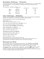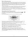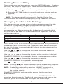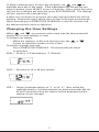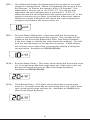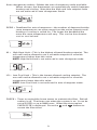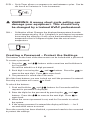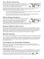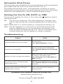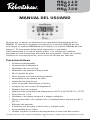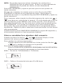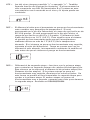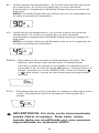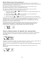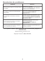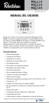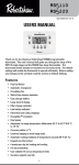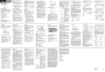
1
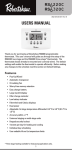
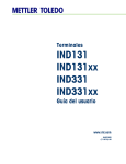
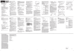
RS6110
RS6220
RS6320
352-00057-001 Rev B
USERS MANUAL
Thank you for purchasing a Robertshaw RS6000 programmable
thermostat. This user’s manual will guide you through the setup of the
RS6110 single stage, the RS6220 two stage and the RS6320 three stage*
thermostats. The thermostat should already be mounted and correctly
wired. The default settings will enable the thermostat to operate
efficiently. Before making any changes to the schedule read the section
on Default Settings.
Features
• Pop-Up Wizard
• Automatic changeover
• Circulating Fan
• Worry-Free memory retention
• Easy change battery
• Large back lit display
• Filter change reminder
• Low battery indicator
• Fahrenheit and Celsius displays
• EnergyStar™ compliant
• Dual power
• Adjustable 1st stage temperature differential: 0.5 °F to 3.0 °F (0.5 °C
to 1.5 °C)
• Accuracy within ±1 °F
• Universal staging on multi-stage units
• Automatic heating shutdown if temperature exceeds 99 °F (37 °C)
• Keypad security lockout
• 4 events per day for heating and cooling
• Individual day scheduling
• User settable Hi and Lo temperature limits
* Three stage heating available for heat pump applications only.
1
Application
The Robertshaw 6000 family of thermostats is designed to control gas,
electric, oil, heat pump, and millivolt heating and electric cooling
systems. The RS6110 is a single stage thermostat while the RS6220 is a
two-stage thermostat. The RS6320 can support three stages of heating
and two stages of cooling in heat pump applications.
The RS6000 thermostats can have a schedule programmed for each day.
IMPORTANT SAFETY INFORMATION
WARNING:
• Always turn off power at main fuse or circuit breaker panel before
installing, removing, cleaning, or servicing thermostat.
• Read all the information in this manual before installing this
thermostat.
• This is a 24V AC low-voltage thermostat. Do not install on voltages
higher than 30V AC.
• All wiring must conform to local and national building and electrical
codes and ordinances.
• Do not short (jumper) across terminals on the gas valve or at the
system control to test installation. This will damage the thermostat
and void the warranty.
• Do not connect ground to any terminal in this unit.
• This thermostat is configured with automatic compressor protection
to prevent damage because of short cycling or extended power
outages. Short cycle protection provides a delay between heating
and cooling cycles on heat pumps.
Detailed mounting and wiring instructions are explained in the
Installation Manual.
Refer to the Pop-Up Wizard section in the installation manual for a
complete list of factory defaults and contractor settings.
Providing Power to the Thermostat
For wiring diagrams refer to the Installation Manual.
The thermostats will operate using 24V AC or two AA batteries. When
the two AA batteries are installed the thermostat will continue to run if
the 24V AC fails.
2
Installing or Changing the Batteries
To remove the battery compartment gently
squeeze the ribbed edges on both sides.
The battery compartment will pull down from
the thermostat body and will detach. Install
two AA batteries following the polarity as
shown inside the compartment. Place
compartment back into the thermostat.
When the batteries are low the thermostat
will enter a low battery mode.
Low battery mode has two levels.
• LEVEL 1: The low battery icon will be displayed. The
thermostat will continue to operate. Replace the
batteries as soon as possible
• LEVEL 2: The low battery icon will flash. If 24V AC is
present the thermostat will continue to operate if
the batteries are discharged or removed. If 24V AC
is not present the thermostat runs on batteries only
and THE SYSTEM WILL NOT OPERATE. Replace
batteries immediately.
Replace batteries if leaving thermostat unattended for more than
30 days.
The clock will continue to run for 10 minutes when the batteries
are removed.
Display Description
The thermostat display will show information that is being used during
operation or programming. This illustration shows all of the display’s
possibilities with an explanation.
1
2
4
3
5
6
14
7
13
9
12
11
10
8
1. Event Names (used for editing schedule).
2. Day is displayed on Idle screen. Also used to display day ranges
when editing the schedule (e.g., SAT SUN for weekend).
3. Used with clock to display hold duration (e.g., FOR 2h).
4. On when running a schedule.
5. Used with setpoint.
6. Used along with clock for service reminders (e.g., CHECK HP).
7. Used for time, current setpoint, and some configuration data (e.g.,
filter hours).
8. HVAC mode and status. Icons blink when active. A is for Auto, 2 is
for second stage, E is for emergency.
9. Indicates when security is active.
10.Low battery indicator.
11.Not used.
12.Used for ambient temperature and configuration data (e.g., first
stage differential, F or C, etc.).
13.Fan status (rotates when active).
14.Fan mode selected by pressing FAN button.
3
Schedule Settings – Defaults
This thermostat is preprogrammed with a schedule that is recommended
by EnergyStar™. The schedule is designed to lower energy costs
year-round.
The default schedule settings are:
Time
Cooling °F
Heating °F
Morn
6:00 am
78
70
Day
8:00 am
85
62
Eve
6:00 pm
78
70
Nite
10:00 pm
82
62
User Settings – Defaults
During any program changes the display returns back to the operating
display if a button has not been pushed in 10 seconds.
The temperature scale is set to Fahrenheit.
Night light is on.
The first stage differential is 1 °F.
The second stage differential (RS6220) is 2 °F.
The second stage delay is 20 minutes.
Third stage delay (RS6320) is 20 minutes.
Auto changeover is enabled.
Auto changeover deadband is 3 °F.
Filter reminder length is off.
Temperature offset is 0 degrees.
The HI heat limit is 90 °F (32 °C).
The LO cool limit is 45 °F (7 °C)
The operation mode is OFF.
The fan setting is Auto.
The keypad has no password protection.
Refer to the pop up wizard section in the installation manual for a
complete list of factory defaults and contractor settings.
Emergency Heat
Your system may include Emergency Heat. The RS6220 and RS6320
thermostats have an emergency heat capability for multi stage heat
pump systems. To determine if your system is capable of using
emergency heat contact your contractor. Use the
button to enter
the EMER mode. An E will be displayed with the Heat symbol. This
mode is used to bypass the heat pump when it needs servicing or when
it cannot keep up with the heat demand.
4
Auto Changeover
Auto changeover is the ability of the thermostat to switch automatically
between heating settings and cooling settings. This is useful in Spring
and Fall when the days are warm and the nights are cool. In heat mode
if the room continues to warm beyond a set threshold the thermostat
switches to the cool mode and the associated cooling settings. The
reverse is also true.
As the room temperature changes, the thermostat will call for heating or
cooling as needed. To prevent the heating and cooling systems from
overriding each other, an auto changeover deadband is used.
The deadband is the minimum temperature swing before changing from
heating to cooling or vice versa. The larger the deadband the more the
room temperature will vary.
Operating the Thermostat
Any setting can be changed when it is flashing by pushing
or
If a button is not pushed for 10 seconds the thermostat returns
to operation.
The following buttons can be accessed from the front panel.
START/STOP SCHEDULE: Switches between running a schedule and
manual (permanent override). Cancels a temporary override.
EDIT SCHEDULE: Use this button to start editing the schedule. Push
repeatedly to move through the selections.
SELECT: Used to select the days that the new schedule will be copied to.
SET TIME: Sequences through the hour, minute and day.
LIGHT BAR: Turns on the display back light for 10 seconds.
FAN: Turns fan to AUTOMATIC, CIRCULATE or ON.
UP ARROW: Raises the setpoint or increases flashing item.
DOWN ARROW: Lowers the setpoint or decreases flashing item.
HEAT/COOL: Toggles through OFF, HEATING, COOLING, and AUTO. If
using an RS6220 or RS6320 and configured as HP then emergency heat
is also displayed.
5
Setting Time and Day
To adjust the time and day settings press the SET TIME button. The hour
will flash. If a button is not pushed in 10 seconds the thermostat returns
to operation. To change the settings:
1. Use the
and
buttons to change the flashing number.
2. Press the SET TIME button to move through hour, minutes and day
of week.
3. Make changes as needed. They will be saved automatically.
NOTE: The thermostat will not correct for Daylight Saving Time.
The thermostat will now function properly using the default schedule.
Changing the Schedule Settings
This thermostat can operate using a single setpoint by overriding the
schedules. If you will be using this thermostat for single setpoint
operation skip to Overriding the Schedule.
The chart below represents one day’s programming schedule. To make
programming your thermostat quicker and easier, recreate the table
for each day of the week on a separate piece of paper, and refer to it
while programming.
Time
Cool
Heat
Morning
Day
Evening
Nite
Press START/STOP SCHEDULE at any time to exit and save your settings.
Push START/STOP SCHEDULE. The display will show a day flashing at
the top. If a button is not pushed in 30 seconds the thermostat returns
to normal operation.
Use the
or
to change the hour of the start time if desired.
Push EDIT SCHEDULE to move to minutes.
Use the
or
to change the minutes of the start time if desired.
Push EDIT SCHEDULE to move to the heat or cool temperature setting.
Use the
or
to change the temperature setpoint.
Push EDIT SCHEDULE to move to the other setpoint.
Use
or
to change the temperature setpoint.
NOTE: Pressing
will switch between cooling and heating setpoints.
Pressing Set Time button will switch back to the event time.
NOTE: The heating and cooling setpoints CANNOT be entered as
crossed. That is, the cooling setpoint CANNOT BE lower than
the heating setpoint.
Push EDIT SCHEDULE and repeat this process for the remaining
three settings.
After a single day setting is complete pressing EDIT SCHEDULE will
enter into a copy program. To skip the copy program and move to the
next day, press EDIT SCHEDULE and repeat the above steps.
6
To begin selecting days for the copy program, use
and
to
highlight each day of the week. If the highlighted day should use the
same schedule, press SELECT to turn on that day. Once all the days that
will use this schedule are selected, press EDIT SCHEDULE. The settings
will be copied to the selected days.
If there are more days to program, the next unprogrammed day will be
blinking. Repeat the steps above until all days have been programmed.
When finished press START/STOP SCHEDULE or wait 30 seconds and
the thermostat will return to operation.
Changing the User Settings
When
and
are pressed at the same time the thermostat will
display the current settings in order.
To change any setting:
When the setting is visible and flashing press the
arrows to adjust the number on the screen.
or
To exit the changes and save:
Press START/STOP SCHEDULE. The thermostat will return
to operation.
SCAL = Scale in °F (Fahrenheit) or °C (Celsius).
CLOC = Set clock to 12 or 24 hour format.
LITE = Display backlight always on ”y” or off ”n”. Also called the
nightlight feature. If the thermostat has been wired with 24V AC
(R and C terminals) then this feature will be displayed and the
setting can be changed.
7
DIFF = The differential keeps the thermostat from turning on for small
changes in temperature. When in Fahrenheit the range is 0.5 to
3.0 Degrees. In Celsius the range is 0.5 to 1.5 Degrees. The
differential is factory set at 1.0 °F (0.5 °C). This means that
whenever the room temperature is more than 1 °F (0.5 °C)
different from the set temperature the system will turn on. If the
system is turning on too often, increase the differential setting.
Note that a larger differential will mean the room temperature
changes more before the system turns on.
DIF2 = Second Stage Differential = Operates with the first stage to
control a second heating/cooling system. This number will be
added to the first stage differential (See: Two Stage Systems).
If the first stage is running too often lower the settings. This will
turn the second stage on to help the first stage. If both stages
are coming on too often then increase this setting to delay the
second stage. Available on RS6220/RS6320.
DLY2 = Second Stage Delay = This timer starts when the first stage turns
on. It resets when the first stage turns off. If this timer runs out
the second stage will turn on (See Two Stage Systems).
Available on RS6220/RS6320.
DLY3 = Third Stage Delay = This timer starts when the second stage
turns on. It resets when the second stage turns off. If this timer
runs out the third stage will turn on. Available on RS6320 only.
(See Three Stage Systems).
8
Auto changeover enable = Makes the auto changeover mode available.
When chosen, the thermostat can automatically switch between
heating and cooling. Note that the High and Low setpoint limits
are not enforced in auto changeover mode.
DEDB = Deadband for auto changeover = the number of degrees that the
room temperature can move away from the active setpoint until
heating or cooling is called for. The larger the deadband the
more the room temperature will vary. This can be from heat to
cool or cool to heat.
HI = High Heat Limit = This is the highest allowed heating setpoint. The
user will not be allowed to set a schedule setpoint or override
temperature higher than this value.
NOTE: High Heat Limit is not enforced in auto changover mode.
LO = Low Cool Limit = This is the lowest allowed cooling setpoint. The
user will not be allowed to set a schedule setpoint or override
temperature lower than this value.
NOTE: Low Cool Limit is not enforced in auto changover mode.
CHECK = Timer to remind the home owner to maintain the filter. Default
setting is off. The timer runs when the system is on. It can be
set at 0 (OFF) or up to 9900 hours. When the time expires
CHECK FLTR is displayed. Press the
and
buttons to
restart the filter timer.
9
CYCL = Cycle Timer allows a compressor to rest between cycles. Can be
set from 0 to 5 minutes in 1 min increments.
WARNING: A wrong short cycle setting can
damage your equipment. This should only
be changed by a trained HVAC professional.
CAL =
Calibration offset. Changes the displayed temperature from the
actual temperature by +3 to -3 degrees in one degree increments.
Increasing the offset by +2 will cause the thermostat to display a
temperature that is 2 degrees higher than the actual room
temperature
Creating a Password – Protect the Settings
The buttons on the front of the thermostat can be locked with a password.
To create a password:
1. Press the
and
buttons at the same time and hold them in
for 5 seconds.
You will be asked for a 4 digit password.
2. Each digit is set using the
and
buttons. Press the
move to the next digit. Press
to move back.
to
3. The password is saved after 5 seconds.
All of the front buttons are now locked out until the password is entered.
Pressing any button will cause to flash.
To unlock the buttons:
1. Push and hold the
and
buttons for 5 seconds until the
request for password is displayed.
2. Enter the digits for the password by pressing the
buttons. Press the
move back.
and
to move to the next digit. Press
to
3. When the correct password is set, wait for 5 seconds to unlock
the system.
4. If the wrong password is entered the display will flash ---- for 5
seconds then return to normal.
Once the security has been disabled, a password needs to be recreated
to protect the settings.
10
Two Stage Systems
A 2nd stage is a second or additional system
that will provide extra heating or cooling. When
a 2nd stage is operating the display will show
the number 2 by the heat/cool icons.
A temperature differential (default value is 2.0 °F or 1.0 °C) and time
delay (default value 20 minutes) control the 2nd stage cycle.
Operation of the 2nd stage begins when:
• The room temperature changes from the setpoint by the sum of the
1st and 2nd stage differential settings.
• The first stage has been on for the specified delay time, but the
heating/cooling demand has not yet been met.
Three Stage Systems
A 3rd stage is a third or additional system that will
provide extra heating in heat pump applications.
When a 3rd stage is operating the display will
show the number 2 and E by the heat icon.
A time delay (default value 20 minutes) controls the 3rd stage cycle.
This time delay starts when the second stage turns on.
Energy Efficient Recovery
With Energy Efficient Recovery, the thermostat “Looks Ahead” to the
next event and attempts to reach the next setpoint at the exact time of
the event. If you have two stages, the thermostat will use only the first
stage during this period. This is more efficient than waiting until the
next event and then turning on both first and second stages.
Backlit Display
This thermostat is equipped with a backlight to make viewing the display
easy. Press the
button to activate the backlight. The backlight will
turn off after 10 seconds of inactivity. If the thermostat is wired to have
the backlight stay on all the time the night light can be turned on/off in
the settings menu.
Overriding the Schedule Settings
When the thermostat has been programmed, the settings and the
schedule are saved. The thermostat will run to the schedule unless an
override is entered.
Two methods of override are available.
Permanent Override
Press START/STOP SCHEDULE until the word SCHEDULE is not shown
on the display. A Permanent Override allows the thermostat to maintain
a setpoint indefinitely. To switch between Schedule and Permanent
Override, press START/STOP SCHEDULE button. Press
or
to
change the setpoint. The heat or cool mode should be selected.
11
Temporary Override
When the thermostat is running to a schedule, an override allows the
thermostat to function with a single setpoint for a time period.
A temporary override is entered as a setpoint for a number of hours.
1. Press
or
of hours.
to display the flashing setpoint and the number
2. Use
to change the setpoint.
and
3. Press SET TIME to move to the hours.
4. Use
and
to set the length of the override.
After 5 seconds the thermostat will start operation of the override. The
display will show room temperature, and the setpoint will alternate with
the number of hours remaining in the override.
The schedule will resume after the programmed override time expires.
Cancel the override by pressing START/STOP SCHEDULE.
Determining Operating Setpoint
When the thermostat is using a schedule the temperature setpoint
originates from the schedule settings.
When one of the schedule overrides is active the setpoint has been
entered as part of the override.
Use the display to determine the origin of the current temperature setpoint.
Permanent Override – The day, time and “schedule” are not displayed.
Temporary Override – The display alternates hours of override with
setpoint.
12
Automatic Shut-Down
The thermostat will not display the room temperature if the temperature
goes higher than 99 °F (37 °C) or lower than 32 °F (0 °C).
The display will show HI or LO. The thermostat continues to control
heating and cooling and will resume the display of real time information
when the room temperature is back inside the display’s range.
Setting the Fan To ON, AUTO or CIRC
The fan has 3 settings: On, Auto, or Circ. Press the
among the three.
ON:
button to switch
The fan is on constantly. The room temperture, set points, and
status of the heating and cooling equipment has no effect on the
fan.
AUTO: When there is a call for heating or cooling the fan will turn on.
CIRC: The fan operates in a cycle of on for 10 minutes and off for 20
minutes. When there is a call for heating or cooling the cycle
stops and the fan responds to the call. The fan circulation cycle
resumes when the call for heating or cooling is satisfied.
Troubleshooting
Problem
Action
Thermostat does not turn on system.
Check wiring.
(See Wiring Diagrams section.)
System turns on too often.
Increase temperature differential.
(See To Make Changes to the Settings
section.)
System fan does not operate properly.
Move fan option switch to either gas
or electric, to match system.
(See Setting the Fan to ON, AUTO, or
CIRC section.)
Thermostat does not display proper
room temperature.
Check F/C (Fahrenheit/Celsius) setting.
(See To Make Changes to the Settings
section.)
Display shows HI or LO and room
temperature is normal.
Call a licensed service person to
replace/repair.
If problems with thermostat cannot be resolved, call:
www.invensyscontrols.com
or
Technical Support: (800) 445-8299
13
Five Year Limited Warranty
Invensys Controls warrants to the original contractor installer, or to the
original consumer user, each new Robertshaw thermostat to be free
from defects in materials and workmanship under normal use and
service for a period of Five (5) years from date of purchase. This
warranty and our liability does not apply to batteries or merchandise
that has been damaged by misuse, neglect, mishandling, alterations,
improper installation, or use in a way other than in accordance with
Invensys Controls recommendations and instructions.
Invensys Controls agrees to repair or replace at its option any
thermostat under warranty provided it is returned within the warranty
period, postage prepaid, with proof of the date of purchase. Cost of
thermostat removal or reinstallation is not the responsibility of Invensys
Controls.
Repair or replacement as provided under this warranty is the exclusive
remedy of the consumer. Invensys Controls shall not be liable for any
incidental or consequential damages for breach of any express or
implied warranty on this product, or under any other theory of liability.
Except to the extent prohibited by applicable law, any implied warranty
of merchantability or fitness for a particular purpose on this product is
limited to the duration of this warranty.
Some states do not allow the exclusion or limitation of incidental or
consequential damages, or allow limitations on how long an implied
warranty lasts, so the above limitations or exclusions may not apply to
you. This warranty gives you specific legal rights, and you may also
have other rights which vary from state to state.
For warranty returns, send thermostat, shipping prepaid to:
Invensys Controls
Warranty Claims Department
515 S. Promenade
Corona, CA 91719
In Canada:
Invensys Controls
3505 Laird Road Unit #14
Mississauga, Ontarion L5L 5Y7 Canada
Attn: Warranty Department
14
NOTES
15
515 South Promenade Avenue
Corona, CA 92879-1736
United States of America
www.invensyscontrols.com
©2008 Invensys Controls 2/08
352-00057-001 Rev B
16
RS6110
RS6220
RS6320
352-00057-001 Rev B
MANUAL DEL USUARIO
Gracias por comprar un termostato programable Robertshaw Serie
RS6000. El manual le ayudará a programar el modelo RS6110 de una
sola etapa, el modelo RS6220 de dos etapas y el modelo RS6320 de tres
etapas*. El termostato debe estar instalado y conectado
adecuadamente a la red de electricidad. Los ajustes por defecto
permiten el funcionamiento eficiente del termostato. Antes de realizar
cambios en la programación, lea la sección Ajuste por defecto.
Características
• Asistente desplegable
• Conmutación automática
• Ventilador de circulación
• Retenedor de memoria Worry-Free
• Fácil cambio de pilas
• Visor grande con iluminación posterior
• Recordatorio de cambio de filtro
• Indicador de pilas bajas
• Visor en grados Fahrenheit y Celsius
• Cumple con las normas EnergyStar™
• Sistema dual de energía
• Diferenciales ajustables de temperatura: 0.5 ºF a 3.0 ºF (0.5 ºC a 1.5 ºC)
• Precisión de ±1 ºF
• Unidades con etapa universal o etapas múltiples
• Cierre automático de calefacción si la temperatura supera los 99 °F
(37 °C)
• Bloqueo del teclado
• 4 eventos por día para calefacción y refrigeración
• Programable para 7 días
• Límites superior e inferior de temperatura a elección del usuario
* Calefacción con tres etapas disponible solamente para aplicaciones de bomba de calor.
1
Aplicación
La familia de termostatos Robertshaw 6000 está diseñada para controlar
sistemas de refrigeración eléctrica y de calefacción de gas,
electricidad, petróleo, bombas de calor y minivolt. El modelo RS6110 es
un termostato de una sola etapa y el RS6220 es un termostato de dos
etapas. El RS6320 puede soportar tres etapas de calefacción y dos
etapas de refrigeración en aplicaciones con bomba de calor.
Los termostatos RS6000 pueden tener un horario programado para
cada dia.
ADVERTENCIAS IMPORTANTES SOBRE
SEGURIDAD:
• Interrumpa siempre el suministro de electricidad desde el
interruptor principal o desde el panel del disyuntor antes de
instalar, retirar, limpiar o reparar el termostato.
• Lea toda la información que aparece en este manual antes de
instalar el termostato.
• Este es un termostato de bajo voltaje 24V CA. No instale con voltaje
superior a 30V CA.
• Todas las conexiones de cableado deben cumplir con las normas y
disposiciones locales y nacionales que rigen en materia de
construcción y electricidad.
• No deben puentearse los terminales de la válvula de gas ni el
control del sistema para probar la instalación. Esa práctica
perjudicará el termostato y causará la nulidad de la garantía.
• No conecte a tierra ninguna de los terminales de esta unidad.
• Este termostato está configurado con protección automática del
compresor para prevenir daños por ciclos de corta duración o
cortes prolongados de suministro de energía. La protección de
ciclos de corta duración proporciona un retardo en los ciclos del
compresor en las bombas de calor.
Las instrucciones detalladas de montaje y conexión se incluyen en el
Manual de Instalación.
Consulte la sección Asistente Desplegable Pop-Up Wizard del Manual
de Instalación la lista completa de valores por defecto de fábrica y
programados por el contratista.
Para llevar energía al termostato
Consulte el diagrama de cableado en el Manual de Instalación.
Estos termostatos funcionan con dos pilas AA o con corriente de 24V
CA. Los termostatos que funcionan con pilas y reciben energía de 24V
CA seguirán funcionando si hay un corte de la corriente 24V CA.
2
Para instalar o cambiar las pilas
Para retirar el compartimiento de las pilas, apriete
suavemente los bordes estriados de ambos lados.
El compartimiento de pilas de desprenderá del
cuerpo del termostato. Coloque dos pilas AA según
la indicación de polaridad que figura en el interior
del compartimiento. Vuelva a colocar en el
termostato.
Cuando las pilas están bajas, el termostato empieza a funcionar en
modo baja energía.
El modo pila baja tiene dos niveles.
• NIVEL 1: Aparece en el visor el ícono de pila baja.
El termostato sigue funcionando. Cambie las pilas lo
antes posible.
• NIVEL 2: Titila intermitentemente el ícono de pila
baja. Si llega corriente de la red eléctrica de 24V
CA, el sistema seguirá funcionando aunque las pilas
estén descargadas o se saquen. Si el sistema no
recibe corriente eléctrica y el termostato sólo
funciona con pilas, EL SISTEMA NO FUNCIONARÁ.
Cambie las pilas inmediatamente.
Cambie las pilas si el termostato quedará sin atención durante más de
30 días.
El reloj seguirá funcionado durante 10 minutos sin pilas.
Descripción del visor
El visor del termostato muestra la información que se usa durante el
funcionamiento o la programación. El dibujo muestra las posibilidades
del visor y la explicación.
1
2
4
3
5
6
14
7
13
12
9
11
10
8
1. Nombres del evento (utilizado para edición de programas).
2. El día se muestra en la pantalla de espera. Además es utilizado para mostrar los rangos
de días cuando se editan los programas (p.ej. SAT SUN para los fines de semana).
3. Se usa con el reloj para mostrar la duración de la retención (p.ej. FOR 2h (PARA 2h)).
4. On (Conectado) cuando se ejecuta un programa.
5. Se usa con los puntos de ajuste.
6. Se usa junto con el reloj para recordar el mantenimiento (p.ej. CHECK HP).
7. Se usa para el tiempo, puntos de ajuste actual y datos de alguna configuración (p.ej.
horas del filtro).
8. Modo y estado del HVAC. Los iconos destellan cuando está activo. A es para auto, 2 para
segunda etapa, E para emergencia.
9. Indica que la seguridad está activa.
10.Indicador de batería baja.
11.No se usa.
12.Se usa para temperatura ambiente y datos de configuración (p.ej. diferencial de la
primera etapa, F o C, etc.).
13.Estado del ventilador (gira cuando está activo).
14.Se selecciona el modo del ventilador pulsando el botón FAN.
3
Ajustes de los programas – Valores por defecto
El termostato está preprogramado con una configuración recomendada
por EnergyStar™. La configuración está diseñada para reducir los
costos de energía de todo el año.
El ajuste de la configuración por defecto es:
El ajuste de la configuración por defecto es:
Hora
Refrigeración °F Calefacción °F
Mañana
6:00 am
78
70
Día
8:00 am
85
62
Anochecer 6:00 pm
78
70
Noche
82
62
10:00 pm
Ajustes del usuario – Valores por defecto
Durante cualquier cambio en la programación, el visor vuelve al modo
operación si no se presiona ninguna tecla durante 10 segundos.
La escala de temperaturas está en grados Fahrenheit.
Luz de noche encendida.
El diferencial de primera etapa es 1 ºF.
El diferencial de segunda etapa (RS6220) es 2 ºF.
El retardo de la segunda etapa es de 20 minutos.
El retardo de la tercera etapa (RS6320) es de 20 minutos.
La conmutación automática está activada.
El margen de oscilación para conmutación automática es 3 ºF.
El recordatorio de duración del filtro está apagado.
La compensación de temperaturas es cero grado.
El límite superior de calefacción (HI) es 90 °F (32 °C).
El límite inferior de refrigeración es 45 °F (7 °C)
El modo de operación está OFF (Apagado).
El ajuste del ventilador es Auto.
El teclado no tiene una contraseña de protección.
Consulte en la sección del Asistente Desplegable Pop-Up Wizard del
Manual de Instalación la lista completa de ajustes por defecto de
fábrica y del contratista.
Calefacción de emergencia
Su sistema puede incluir la función calefacción de emergencia. Los
termostatos RS6220 y RS6320 tienen calefacción de emergencia para los
sistemas de bomba de calor con etapas múltiples. Para saber si su
sistema tiene esta función, comuníquese con el contratista. Use las
teclas
para ingresar en el modo EMER. Aparecerá una E con el
símbolo de calefacción. Este modo se usa para hacer un bypass a la
bomba de calor cuando ésta necesita reparación o cuando no puede
dar abasto con la demanda de calefacción.
4
Conmutación automática
La conmutación automática es la posibilidad que tiene el termostato de
cambiar automáticamente del modo calefacción al modo refrigeración y
viceversa. Esta función es útil en primavera y otoño cuando los días son
cálidos y las noches son frescas. En el modo calefacción, si la
habitación se sigue calefaccionando por encima del umbral fijado, el
termostato cambia automáticamente al modo refrigeración y los valores
programados correspondientes. También funciona en sentido inverso.
A medida que cambia la temperatura ambiente, el termostato pedirá
calefacción o refrigeración según sea necesario. Para evitar que los
sistemas de calefacción o refrigeración se sobrecontrolen mutuamente,
se utiliza una banda muerta en la conmutación automática.
La banda muerta es el cambio mínimo de temperatura antes de que
conmute desde calefacción a refrigeración o viceversa. Cuanto más
grande sea la banda muerta, más variará la temperatura ambiente.
Cómo operar el termostato
Cuando los valores programados titilan se pueden modificar
presionando las teclas
o
Si no se pulsa ninguna tecla en 10
segundos, el termostato vuelve a ponerse en funcionamiento.
Puede acceder a las siguientes teclas desde el panel delantero.
START/STOP SCHEDULE (PROGRAMA INICIO/DETENCIÓN): cambia
entre poner en funcionamiento un programa y el modo manual
(sobrecontrol permanente). Cancela el modo sobrecontrol temporario o
por vacaciones.
EDIT SCHEDULE (EDITAR PROGRAMA): Use este botón para empezar a
editar un programa. Presione repetidamente para ir pasando las
opciones.
SELECT: Copiaban el nuevo horario a los días seleccionados.
SET TIME (FIJAR LA HORA): secuencia la hora, minutos y el día.
LIGHT BAR (BARRA DE ILUMINACIÓN): ilumina el visor durante 10
segundos.
FAN (VENTILADOR): pone el ventilador en función AUTOMÁTICA,
CIRCULAR o PRENDIDO.
FLECHA ARRIBA: eleva el punto de ajuste o aumenta el item destellando.
FLECHA ABAJO: disminuye el punto de ajuste o disminuye el ítem
destellando
HEAT/COOL (CALEFACCIÓN/REFRIGERACIÓN): secuencia entre OFF,
CALEFACCIÓN, REFRIGERACIÓN y AUTO. Si usted tiene un modelo
RS6220 o RS6320 y está configurado como HP, también aparece
calefacción de emergencia.
5
Cómo ajustar la hora y el día
Para ajustar la hora y el día, pulse la tecla SET TIME (fijar la hora). La
hora titilará en forma intermitente. Si no se pulsa ninguna tecla en 10
segundos, el termostato vuelve a ponerse en funcionamiento. Para
cambiar los ajustes:
1. Use las teclas
y
para modificar los números que titilan.
2. Pulse la tecla SET TIME (fijar la hora) para avanzar las horas,
minutos y días de la semana.
3. Realice los cambios necesarios. Se guardarán automáticamente.
NOTA: El termostato no se ajustará automáticamente durante el
período de ahorro de luz de día.
Ahora, el termostato funcionará correctamente con los ajustes
por defecto.
Cómo cambiar los ajustes del programa
Este termostato puede funcionar con un único valor deseado activando
el modo sobrecontrol de programaciones. Si usted usa el termostato
con un solo valor deseado vaya directamente a la sección Modo
Sobrecontrol.
El cuadro siguiente representa la programación de un día. Para que la
programación de su termostato sea más rápida y fácil, complete la tabla
para cada día de la semana en un papel separado y consúltelo mientras
escribe la programación.
Hora
Refrigeración
Calefacción
Mañana
Día
Anochecer
Noche
Pulse el START/STOP SCHEDULE (PROGRAMA INICIO/DETENCIÓN) en
cualquier momento para salir y guardar los valores ingresados.
Presione START/STOP SCHEDULE. El visor mostrará un día destellando
en la parte superior. Si no se pulsa ningún botón durante 30 segundos,
el termostato retornará a operación normal.
Use las teclas
para modificar la hora de la hora de inicio si lo desea.
y
Pulse EDIT SCHEDULE (EDITAR PROGRAMA) para avanzar los minutos.
Use las teclas
si lo desea.
y
para modificar los minutos de la hora de inicio
Pulse EDIT SCHEDULE (EDITAR PROGRAMA) para pasar a fijar la
temperatura de calefacción o refrigeración.
Use las teclas
o
para cambiar el valor deseado de la temperatura.
Pulse EDIT SCHEDULE para moverse al otro punto de ajsute.
Use
o
para cambiar el ajuste de temperatura.
NOTA: Al pulsar
se cambiará entre refrigeración y calefacción.
Pulsando el botón Set Time se volverá al evento de tiempo.
6
NOTA: No pueden ingresare valores deseados de calefacción y
refrigeración que se entrecrucen. Es decir, el valor deseado de
refrigeración no puede ser inferior al valor deseado de
refrigeración.
Pulse EDIT SCHEDULE y repita el proceso para los tres puntos de
ajuste restantes.
Si luego de completar los ajustes para un solo día se pulsa EDIT
SCHEDULE se entrará en un programa de copia. Para saltear el
programa de copia e ir al próximo día pulse EDIT SCHEDULE y repita los
pasos anteriores.
Para comenzar seleccionado los días del programa de copia use
y
para destacar cada día de la semana. Si el día destacado usase el
mismo programa, pulse SELECT para activar ese día. Una vez que se
han seleccionado todos los días que van a utilizar este programa pulse
EDIT SCHEDULE. Los ajustes se copiarán en los días seleccionados.
Si hay más días para programar, el próximo día no programado estará
destellando. Repita los pasos anteriores hasta que todos los días hayan
sido programados.
Cuando termine pulse START/STOP SCHEDULE o espere 30 segundos y
el termostato retornará al funcionamiento habitual.
Cómo cambiar los ajustes del usuario
Cuando se pulsas las teclas
and
al mismo tiempo, el visor
mostrará los valores programados en ese momento.
Para cambiar los valores programados:
Cuando aparezca el valor titilando en el visor, pulse las flechas
y
para cambiar los números en la pantalla.
Para salir del modo cambio y guardar:
Pulse el START/STOP SCHEDULE (PROGRAMA INICIO/DETENCIÓN).
El termostato se pondrá nuevamente en funcionamiento.
SCAL = Escala en °F (Fahrenheit) o °C (Celsius)
CLOC = Define el formato del reloj para 12 o 24 horas.
7
LITE = Luz del visor siempre prendida ”y” o apagada ”n”. También
llamada función de iluminación nocturna. Si el termostato ha
sido conectado con 24V CA (terminales R y C) entonces esta
característica será mostrada en el visor y el ajuste puede ser
cambiado.
DIFF = El diferencial evita que el termostato se ponga en funcionamiento
ante cambios muy pequeños de temperatura. Si está
programado en la escala Fahrenheit, el rango de oscilación es de
0.5 a 3.0 grados. Si está programado en la escala Celsius, el
rango de oscilación es de 0.5 a 1.5 grados. El diferencial está
fijado de fábrica en 1.0 ºF (0.5 ºC). Esto significa que el sistema
se pondrá en funcionamiento toda vez que la temperatura
ambiente difiera en más de 1 ºF (0.5 ºC) de la temperatura
deseada. Si el sistema se pone en funcionamiento muy seguido,
aumente el valor del diferencial. Tenga en cuenta que con un
diferencial más elevado, la temperatura ambiente se modificará
más antes de que el sistema se ponga en funcionamiento.
DIF2 = Differencial de segunda etapa = funciona con la primera etapa
para controlar un segundo sistema de calefacción/refrigeración.
Este número se incorporará al diferencial de primera etapa (Ver:
Sistemas de dos etapas). Si la primera etapa se pone en
funcionamiento muy seguido, disminuya los valores fijados. De
esta forma se pondrá en funcionamiento la segunda etapa para
ayudar a la primera etapa. Si ambas etapas se ponen en
funcionamiento muy a menudo, aumente este valor para demorar
la segunda etapa. Available on RS6220/RS6320.
8
DLY2 = Demorea de la segunda etapa = este temporizador empieza a
funcionar cuando se pone en funcionamiento la primera etapa.
Se reprograma cuando la primera etapa deja de funcionar. Si se
termina el plazo del temporizador, se pone en funcionamiento la
segunda etapa (Ver Sistemas de dos etapas). Available on
RS6220/RS6320.
DLY3 = Retardo de la Tercera Etapa = Este temporizador comienza a
funcionar cuando se conecta la segunda etapa. Se repone
cuando la segunda etapa deja de funcionar. Si se termina el plazo
de este temporizador se pone en funcionamiento la tercera etapa.
Disponible solamente en el RS6320 (Ver Sistemas de tres etapas).
Conmutación automática activada = Hace que esté disponible el modo
conmutación automática. Cuando se lo elije., el termostato
puede conmutar automáticamente entre calefacción y
refrigeración. Nótese que los puntos de ajuste límites Alto y Bajo
no son respetados en el modo conmutación automática.
DEDB = Margen de oscilación para conmutación automática = cantidad
de grados que la temperatura ambiente puede alejarse del valor
deseado hasta que empiece a funcionar el modo calefacción o
refrigeración. Cuanto más amplio sea el margen de oscilación
más variará la temperatura ambiente. Esto funciona de
calefacción a refrigeración y viceversa.
9
HI = Límite superior de temperatura = es el valor más elevado de ajuste
de calefacción. El usuario no podrá fijar un valor deseado
programado ni temperatura del Modo Sobrecontrol por encima de
este valor.
NOTA: Los límites Superiores de Calefacción no son respetados en
el modo conmutación automática.
LO = Límite inferior de temperatura = es el valor inferior de ajuste de
refrigeración. El usuario no podrá fijar un valor deseado
programado ni temperatura del Modo Sobrecontrol por debajo de
este valor.
NOTA: Los límites Inferiores de Refrigeración no son respetados en
el modo conmutación automática.
CHECK = Recordatorio para realizar el mantenimiento del filtro. Por
defecto, este control está desactivado. El temporizador
funciona cuando el sistema se enciende y se puede fijar en 0
(apagado) o en un valor de hasta 9900 horas. Cuando finaliza el
tiempo, aparece en el visor CHECK FLTR. Pulse los botones
y
para volver a poner en funcionamiento el temporizador
del filtro.
CYCL = El temporizador de ciclo le permite al compresor descansar entre
ciclos. Se puede fijar de 0 a 5 minutos en incrementos de 1
minuto.
ADVERTENCIA: Un ciclo corto inconveniente
puede dañar el equipo. Este valor únicamente debe ser modificado por una persona
especializada en sistemas HVAC.
10
CAL =
Compensación de calibración. Cambia la temperatura exhibida
de la temperatura real entre +3 y -3 grados en incrementos de un
grado. Aumentar la compensación en +2 significa que el
termostato mostrará una temperatura que es 2 grados superior a
la temperatura ambiente real.
Cómo crear una contraseña – Proteja los ajustes
Las teclas que aparecen en la parte delantera del termostato pueden
bloquearse con una contraseña.
Para crear una contraseña:
1. Pulse las teclas
y
simultáneamente durante 5 segundos.
Se le pedirá que ingrese una contraseña de cuatro dígitos.
2. Cada dígito se fija pulsando las teclas
y
Pulse la tecla
para pasar al dígito siguiente. Pulse la tecla
para volver
atrás.
3. La contraseña queda guardada después de 5 segundos.
Todas las teclas de la parte anterior ahora están bloqueadas y
permanecerán bloqueadas hasta que se ingresa la contraseña. Si pulsa
cualquier tecla aparecerá el ícono .
Para destrabar las teclas:
1. Pulse y mantenga oprimidas las teclas
y
hasta que el sistema le solicite la contraseña.
5 segundos
2. Entre los dígitos para la contraseña pulsando los botones
Pulse
para ir al próximo dígito. Pulse
y
.
para retroceder.
3. Cuando se haya logrado la contraseña correcta, espere 5 segundos
para desbloquear el sistema.
4. Si se ha entrado una contraseña errónea el visor destellará ---durante 5 segundos y luego retornará al estado normal.
Una vez que haya desactivado la protección de seguridad, deberá
volver a crear otra contraseña para proteger los ajustes ingresados.
Sistemas de dos etapas
La segunda etapa es un sistema secundario o
adicional que proporcionará calefacción o
refrigeración extra. Cuando está en
funcionamiento la segunda etapa, el visor
mostrará el número 2 a través de los íconos de
refrigeración y calefacción.
Un diferencial de temperatura (el valor por defecto es 2,0 ºF ó 1,0 ºC) y
un retardo de tiempo (el valor por defecto es 20 minutos) controlan el
ciclo de la segunda etapa
11
La segunda etapa vuelve a ponerse en funcionamiento cuando:
• La temperatura ambiente se aleja del valor deseado en un
incremento que es igual a la suma de los valores diferenciales de la
primera y la segunda etapa.
• La primera etapa ha estado funcionando durante el tiempo de
retardo especificado, pero no se ha alcanzado aún la demanda de
calefacción/refrigeración.
Sistema de tres etapas
Una tercera etapa es un tercer sistema o sistema
adicional que proporcionará calefacción extra en
las aplicaciones con bomba de calor. Cuando la
3er etapa está en operación el visor mostrará el
número 2 y la letra E en el icono de calor.
Un retardo de tiempo (el valor por defecto es 20 minutos) controla el
ciclo de la tercera etapa. Este tiempo de retardo arranca cuando se
conecta la segunda etapa.
Energy Efficient Recovery™
Con esta función, el termostato prevé el evento siguiente y trata de
alcanzar el valor deseado próximo en el momento exacto del evento. Si
el sistema tiene dos etapas, el termostato usará únicamente la primera
etapa durante este período. Este sistema es más eficiente que esperar
hasta que se presente el evento siguiente y luego poner en
funcionamiento la primera y segunda etapas.
Visor con iluminación trasera
El termostato está equipado con una luz posterior para ver el visor con
más facilidad. Pulse la tecla
para activar la luz. La luz se apaga
después de 10 segundos sin actividad. Si el termostato está conectado
para que la luz posterior esté prendida siempre, la luz nocturna se
puede prender y apagar desde el menú.
Cómo sobrecontrolar los ajustes del programa
Cuando se programa el termostato, se guardan los valores y el
programa. El termostato cumplirá el programa salvo que se ingrese el
Modo Sobrecontrol.
El Modo Sobrecontrol tiene dos variantes.
Modo Sobrecontrol permanente
Pulse el START/STOP SCHEDULE (PROGRAMA INICIO/DETENCIÓN)
hasta que la palabra SCHEDULE desaparezca del visor. Aparece el valor
deseado de temperatura. El termostato llamará el modo calefacción o
refrigeración para mantener el valor deseado de temperatura. Pulse las
teclas
o
para modificar el valor deseado. Se debe seleccionar
el modo calefacción o refrigeración.
12
Modo Sobrecontrol de programas
Cuando el termostato está funcionando conforme a un programa, el
modo sobrecontrol le permite al termostato funcionar con un único valor
deseado durante un cierto tiempo.
Se ingresa el Modo Sobrecontrol temporal como un nuevo valor
deseado durante una cierta cantidad de horas.
Se ingresa el Modo Sobrecontrol por vacaciones como un valor
deseado durante una cierta cantidad de días.
1. Pulse las teclas
cantidad de horas.
o
para mostrar los valores deseados y la
2. Pulse las teclas
y
para modificar el valor deseado.
3. Pulse SET TIME para pasar a las horas.
4. Use las teclas
y
para fijar la duración de la cancelación.
Después de 5 segundos, el termostato empezará a funcionar en el modo
sobrecontrol. El visor mostrará la temperatura ambiente y el valor
deseado aparecerá intermitentemente con la cantidad de horas que
quedan en el modo sobrecontrol.
Cuando termine el tiempo programado en el modo sobrecontrol, se
reanudará el programa. Cancele el modo sobrecontrol pulsando
START/STOP SCHEDULE (PROGRAMA INICIO/DETENCIÓN).
Cómo determiner el ajuste de operación
Cuando el termostato está usando un programa, los valores deseados
de temperatura se originan a partir de los valores fijados para el
programa.
Cuando uno de los modos de sobrecontrol se activa, el valor deseado se
origina a partir de la temperatura del modo sobrecontrol.
Use el visor para determinar el origen del valor deseado de temperatura
actual.
Modo sobrecontrol permanente – No aparecen el día, la hora y el
programa.
13
Modo sobrecontrol temporario – El visor alterna las horas de modo
sobrecontrol con el valor deseado.
Cierre automático
El termostato no mostrará valores de temperatura superiores a 99 °F
(37 °C) o inferiores a 32 °F (0 °C).
Si eso sucede, el visor mostrará HI o LO. El termostato sigue
controlando la calefacción y la refrigeración y mostrará la temperatura
cuando los valores se encuentren entre 32 °F (0 °C) y 99 °F (37 °C).
Para fijar el ventilador en ON, AUTO o CIRC
El ventilador tiene tres modos: On, Auto, y Circ. Pulse la tecla
cambiar de modo del ventilador.
ON:
para
el ventilador funciona constantemente. La temperatura ambiente,
los valores deseados y el estado del equipo de calefacción y
refrigeración no tienen efecto sobre el ventilador.
AUTO: el ventilador se pone en marcha cuando se requiere el servicio de
refrigeración o calefacción.
CIRC: El ventilador funciona en ciclos de 10 minutos de actividad y 20
minutos de descanso. Cuando se requiere el servicio de
calefacción o refrigeración, el ciclo se interrumpe, y el ventilador
responde al llamado. El ciclo se circulación del ventilador se
reinicia cuando se ha dado respuesta al llamado de calefacción o
refrigeración.
14
Resolución de problemas
Problema
Solución
El termostato no pone en funcionamiento
el sistema.
Verifique el cableado.
(Ver sección Diagramas de cableado en
el Manual de Instalación.)
El sistema se pone en funcionamiento
muy pronto.
Aumente el diferencial de temperatura.
(Ver sección Para cambiar la
programación.)
El ventilador no funciona correctamente.
Cambie la opción del ventilador a gas o
electricidad para adecuarlo al sistema.
(Ver sección Para fijar el ventilador en
ON, AUTO o CIRC.)
El termostato no muestra la temperatura ambiente correcta.
Verifique el ajuste de la escala F/C
(Fahrenheit/Celsius).
(Ver sección Para cambiar la
programación.)
El visor muestra HI o LO y la temperatura ambiente es normal.
Llame a un técnico especializado para
cambiar o reparar.
Si no puede resolver algún problema con su termostato, póngase en
contacto con
www.invensyscontrols.com
o
Soporte Técnico: (800) 445-8299
15
Garantia Limitada de 5 años
Invensys Controls garantiza al instalador contratista original o al usuario
original que cada termostato Robertshaw nuevo no tendrá defectos en
componentes ni en construcción con el uso y mantenimiento normal
durante un período de cinco (5) años desde la fecha de la compra. Esta
garantía y nuestra responsabilidad no se aplican a las pilas ni a los
productos que hayan sido dañados por maltrato, negligencia, falta de
cuidado en el manejo, modificaciones, instalación incorrecta o uso que
no se condiga con las recomendaciones e instrucciones de Invensys
Controls.
Invensys Controls acepta reparar o cambiar, según su criterio, todo
termostato en garantía siempre y cuando sea devuelto dentro del
período de garantía, con franqueo prepago con prueba de fecha de
compra. El costo del retiro o reinstalación del termostato no es
responsabilidad de Invensys Controls.
La reparación o el reemplazo previstos en la garantía constituyen el
único recurso del consumidor. Invensys Controls no será responsable
de los daños incidentales o emergentes por la violación de cualquier
garantía, expresa o implícita, de este producto, o de cualquier otra
teoría de responsabilidad. Salvo en la medida en que lo prohíba la
legislación correspondiente, toda garantía implícita sobre la
comerciabilidad o aptitud de este producto para un fin específico, se
limita a la duración de esta garantía.
Algunos estados no permiten la exclusión ni la limitación de daños
incidentales o emergentes, ni permiten limitaciones sobre la duración de
las garantías implícitas, por lo que es posible que la limitación o
exclusión anterior no corresponda a su caso. Esta garantía le otorga
derechos legales específicos, y quizás usted también tenga otros
derechos legales que varíen de un estado a otro.
Para devoluciones en garantía, envíe el termostato, con gastos
de envío prepagos a:
Invensys Controls
Warranty Claims Department
515 S. Promenade
Corona, CA 91719
En Canadá:
Invensys Controls
3505 Laird Road Unit #14
Mississauga, Ontario L5L 5Y7 Canada
Attn: Warranty Department
515 South Promenade Avenue
Corona, CA 92879-1736
United States of America
www.invensyscontrols.com
©2008 Invensys Controls 2/08
352-00057-001 Rev B
16