Transcript
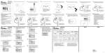
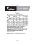
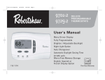
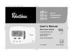
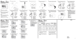
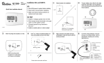
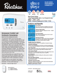
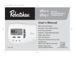
DELUXE
PROGRAMMABLE
THERMOSTATS
1 Select location for installation.
Models 9701i2 and 9725i2
1-1/2"
3 Mark mounting hole locations on wall.
and gently pry forward at all four locations.
1"
Quick Start Installation Manual
2 Open the case with a screwdriver. Place in slot
4 Drill 3/16” holes at marked locations on wall.
5 Align unit base over plastic anchors embedded
Insert plastic anchors into holes.
in wall and secure with the screws provided.
a
Cut
out
opening
b
6 Connect wiring between the thermostat and
equipment. For Model 9701i2 (1 heat / 1 cool;
gas / electric).
Thermostat
Thermostat
TERMINAL DESIGNATIONS
2
1
C
R
Y1 E/W1 O
B
G
-
Drill 3/16 holes
OBG
a
Mark mounting hole
locations on wall using
unit base as template.
1/2"
9701i2
b
R
W1
8 Connect wiring between the thermostat and
9 Connect wiring between the thermostat and
DO NOT
• Install on voltages greater than 30 VAC.
• Short jumper across terminals on the gas
valve or at the system control.
• Connect ground to any terminal in
this unit.
• Install on outside walls or in direct sunlight.
OBG
9725i2
W2
Y2
L
OBG
W1
E
E
E
2
If terminal E is not
supplied, add
jumper across
E/W1 and W2 on
the thermostat.
7
Y2
L
G
B
O
Select either the Fahrenheit or Celsius
temperature scale.
Press Next.
Select Temperature
Scale
°C
°F
PM
Next
Back
Next
8
Set the date.
First, set the month. Press Next.
Then, set the day. Press Next.
Finally, set the year. Press Next.
Select the type of heating system that
will be used with the thermostat.
Press Next.
1st Stage Heat Equip
None
Furnace
Strip
Heat Pump
Set Date
(Month)
Next
Back
1/1/05
Next
9
Choose the time format – 12-hour
clock or 24-hour clock.
Press Next.
Auto changeover allows automatic
switching between heating and
cooling.
Make your selection. Press Next.
Enable
Auto Changeover?
Select Time Format
No
Yes
Next
Back
Yes
Choose either English, Español, or
Français as the display language.
This can always be changed after
the Setup Wizard is complete.
Press Next.
Select Language
English
Español
Français
Back
Equipment Wiring Terminals
Please refer to heat pump
installation manual for
proper terminations
W2
Equipment Wiring Terminals
Please refer to furnace
installation manual for
proper terminations
Set the time. Hours and minutes are
set separately. An AM/PM indicator
automatically changes based on the
hour chosen.
Press Next.
Back
6
Next
To activate the Auto Daylight Saving
Time feature, choose either:
Standard (April – October), or
Extended (March – November).
Press Next.
Auto Adjust For DST?
No
Standard (Apr-Oct)
Extended (Mar-Nov)
10
Service reminders are available for:
Heat System, Heat Pump, Cool
System, Filter, UV Light and
Humidifier Pad. All can be set to OFF
or from 1 to 12 months.
Press Next.
Next
G
Equipment Wiring Terminals
Please refer to furnace
installation manual for
proper terminations
Y1
R
E
C
W2
If terminal E is not
supplied, add
jumper across
E/W1 and W2 on
the thermostat.
11
Y2
L
G
W2
Y2
L
G
B
B
O
O
Contact information can be entered
at the factory. Talk to your
Robertshaw sales representative
about this feature.
To edit information: Use the
or
button to scroll through the character
list. Press Next Char to move to the
next character. Press Accept to move
to the next line, and finish editing.
Set Contact Info
(Name)
ABC HEATERS
123-555-2345
Accept
13 Replace cover on thermostat. Turn on power
to unit and proceed with programming
per instructions on the display or in the
user's manual.
24VAC Common
24VAC
1st stage heating/cooling
Emergency heat (strip)
2nd stage heating
2nd stage cooling
System fault indicator
Cool active reversing valve
Heat active reversing valve
Fan
Recycling Thermostat
If this thermostat REPLACES a thermostat that contains mercury,
DO NOT discard the old thermostat in the regular trash. Mercury
is harmful to humans and the environment. For this reason, do
not open, break, or crush the mercury cell. If mercury leaks from
a damaged cell, DO NOT touch or handle mercury with bare
hands. Use protective, non-absorbent gloves to place mercury
into a sealable container. Fill the container with sand or another
absorbent material and seal the container completely.
Return the mercury or mercury products, in a sealed container, to
Invensys Climate Controls or a local recycling center for proper
disposal. If you have any questions, call Robertshaw technical
support at 1-800-445-8299.
In U.S.:
Invensys Controls Americas
28C Leigh Fisher Blvd.
El Paso, TX 79906
Attn: Mercury Recycling Center
C
Equipment Wiring Terminals
Please refer to heat pump
installation manual for
proper terminations
Equipment Wiring Terminals
Please refer to heat pump
installation manual for
proper terminations
In Canada:
Invensys Controls Americas
3515 Laird Road - Unit #14
Mississauga, Ontario L5L 5Y7
Attn: Mercury Recycling Center
Equipment Wiring Terminals
Please refer to heat pump
installation manual for
proper terminations
NOTES:
DELUXE
PROGRAMMABLE
THERMOSTATS
NOTES:
Operational Mode Chart
No 2nd HVAC Mode
Stage
is Emer
Outdoor
Temperature
1st Stage
(2nd is na)
2nd Stage is a Furnace
Standard2
2nd Stage is
Strip
2nd Stage is a
Heat Pump
Heat Pump
Only4
Add-On2
1st
2nd
1st
2nd
1st
2nd
1st
2nd
Next Char
< Low balance
E/W1
W2
na1
W2
na1
W2
na1
E/W1
na1
Between
balance points
E/W1
Y1
Y1 +
W22
Y1
W2
only2
Y1
Y1 +
W22
Y1
Y1 +
W2
E/W1
Y1
Y1 +
W22
Y1
W2
only2
Y1
Y1 +
W22
Y1
Y1 +
W2
E/W1
Y1
na1
Y1
na1
Y1
na1
Y1
na1
No sensor3
> High balance
Y1
1. The 2nd stage is not used for heating when
the outdoor temperature is not between the
two balance points.
3. When no sensor is present, the thermostat
behaves as if the outdoor temperature is
always between the balance points.
2. Standard and Add-On apply when the 2nd
stage is on. Y1 is either on (Standard) or off
(Add-On).
4. Heat Pump Only applies to the 9725i2 when
it is configured as Heat Pump in both 1st and
2nd stage.
Reminder To Service
Heat System In:
3
Mon
Next
Back
9725i2
R
12hr
24hr
No
OBG
Y1
Back
Would You Like
To Run the
Setup Wizard?
W2
Y2
L
Y1
12:00
5
9725i2
C
R
Y1
E/W1
Y1
Back
Selecting Yes allows you to go
through the setup process.
OBG
24VAC Common
24VAC
1st stage heating/cooling
Emergency heat
2nd stage heating
2nd stage cooling
System fault indicator
Cool active reversing valve
Heat active reversing valve
Fan
Y1
Set Time
(Hour)
NOTE: Use the
or
button to select a list
item or to change the value of a number.
Use the gray buttons below the display to
choose No, Yes, Back, Next, Next Char or
Accept when appropriate.
W2
Y2
L
C
R
Y1 E/W1 W2 Y2 L
O
B
G
R
O
4
C
R
Y1
E/W1
TERMINAL DESIGNATIONS
C
R
Y1 E/W1 W2 Y2 L
O
B
G
-
C
B
1
9725i2
24VAC Common
24VAC
1st stage heating/cooling
Emergency heat
2nd stage heating
2nd stage cooling
System fault indicator
Cool active reversing valve
Heat active reversing valve
Fan
TERMINAL DESIGNATIONS
R
G
The Setup Wizard allows you to quickly step
through the setup process. This guide
shows a typical setup for a basic heating
system. The screens you see depend on
thermostat model and your heating/cooling
configuration.
C
R
Y1 E/W1 W2 Y2 L
O
B
G
-
C
R
Y1
E/W1
indoor sensor (9020i) and the outdoor sensor
(9025i), if used. Use twisted pair wiring (22AWG
minimum) with a maximum length of 300 feet
(or 100m).
Thermostat
Thermostat
TERMINAL DESIGNATIONS
24VAC Common
24VAC
1st stage cooling
1st stage heating
2nd stage heating
2nd stage cooling
Not used
Not used
Not used
Fan
12 Connect wiring between the thermostat and the
equipment. For Model 9725i2 (2 heat / 2 cool;
2 stage heat pump with strip heat).
C
L
Setup Wizard Quick Start Guide
equipment. For Model 9725i2 (2 heat / 2 cool;
heat pump with furnace).
R
Y2
9701i2
24VAC Common
24VAC
1st stage heating/cooling
Emergency heat
Cool active reversing valve
Heat active reversing valve
Fan
O
11 Connect wiring between the thermostat and
C
W2
3
10 Connect wiring between the thermostat and
Thermostat
TERMINAL DESIGNATIONS
C
R
Y1 E/W1 W2 Y2 L
O
B
G
-
OBG
Press anchors into holes until flush.
equipment. For Model 9725i2 (2 heat / 2 cool;
heat pump with strip heat).
Thermostat
W2
Y2
L
DELUXE
PROGRAMMABLE
THERMOSTATS
3
4
equipment. For Model 9725i2 (2 heat / 2 cool;
gas / electric).
C
R
Y1
E/W1
C
R
Y1 E/W1 O
B
G
-
C
R
Y1
E/W1
B
Remove 1/2” of insulation
from end of each wire
110-1180
24VAC Common
24VAC
1st stage cooling
1st stage heating
Not used
Not used
Fan
G
Y1
C
DO
• Shut off all power to system before installing.
• Read entire manual before installing.
• Make sure that all wiring conforms to
national and local codes.
equipment. For Model 9701i2 (1 heat / 1 cool;
heat pump with strip heat [emergency]).
TERMINAL DESIGNATIONS
C
R
Y1
E/W1
Installation DOs and DON’Ts
7 Connect wiring between the thermostat and
Back
Next
Controls Americas
515 South Promenade Avenue
Corona, CA 92879-1736
United States of America
Made in U.S.A
www.about-i-series .com
110-1180