1
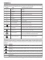
OPERATOR'S MANUAL
Orbital Jig Saw
R3120
Variable Speed
®
This new jig saw has been engineered and manufactured to our high standards for dependability, ease of operation, and
operator safety. When properly cared for, the jig saw will give you years of rugged, trouble-free performance.
WARNING:
To reduce the risk of injury, the user must read and understand the operator’s manual before using this product.
Thank you for buying a RIDGID product.
SAVE THIS MANUAL FOR FUTURE REFERENCE
TABLE OF CONTENTS
■
General Safety Rules ............................................................................................................................................ 3-4
■
Specific Safety Rules ................................................................................................................................................ 4
■
Symbols .................................................................................................................................................................... 5
■
Specifications ........................................................................................................................................................... 6
■
Electrical ................................................................................................................................................................... 6
■
Unpacking ................................................................................................................................................................. 7
■
Applications .............................................................................................................................................................. 7
■
Features ................................................................................................................................................................... 8
■
Assembly .................................................................................................................................................................. 9
■
Operation ........................................................................................................................................................... 10-17
■
Maintenance ........................................................................................................................................................... 18
■
Warranty ................................................................................................................................................................. 19
■
Customer Service Information ................................................................................................................................ 20
INTRODUCTION
The Orbital Jig Saw has many features for making the use of this product more pleasant and enjoyable. Safety,
performance, and dependability have been given top priority in the design of this product making it easy to maintain and
operate.
WARNING:
Do not attempt to use this product until you thoroughly read and completely understand the operator’s manual.
Pay close attention to the safety rules, including Dangers, Warnings, and Cautions. If you use your product
properly and only as intended, you will enjoy years of safe, reliable service.
Look for this symbol to point out important safety precautions.
It means attention!!! Your safety is involved.
WARNING:
The operation of any tool can result in foreign objects being thrown into your eyes, which can result
in severe eye damage. Before beginning operation, always wear safety goggles or safety glasses
with side shields and a full face shield when needed. We recommend Wide Vision Safety Mask for
use over eyeglasses or standard safety glasses with side shields. Always wear eye protection which
is marked to comply with ANSI Z87.1.
2
GENERAL SAFETY RULES
■ Dress properly. Do not wear loose clothing or jewelry. Contain long hair. Keep your hair, clothing, and
gloves away from moving parts. Loose clothes, jewelry, or long hair can be caught in moving parts.
■ Avoid accidental starting. Be sure switch is off before plugging in. Carrying tools with your finger on the
switch or plugging in tools that have the switch on, invites accidents.
■ Remove adjusting keys or wrenches before turning the tool on. A wrench or a key that is left attached
to a rotating part of the tool may result in personal injury.
■ Do not overreach. Keep proper footing and balance
at all times. Proper footing and balance enables better
control of the tool in unexpected situations.
■ Use safety equipment. Always wear eye protection.
Dust mask, nonskid safety shoes, hard hat, or hearing
protection must be used for appropriate conditions.
■ Do not use on a ladder or unstable support.
■ Loose clothes, jewelry, or long hair can be drawn
into air vents.
WARNING:
Read and understand all instructions. Failure to
follow all instructions listed below, may result in
electric shock, fire and/or serious personal injury.
SAVE THESE INSTRUCTIONS
Work Area
■ Keep your work area clean and well lit. Cluttered
benches and dark areas invite accidents.
■ Do not operate power tools in explosive atmospheres, such as in the presence of flammable liquids, gases, or dust. Power tools may create sparks
which may ignite the dust or fumes.
■ Keep bystanders, children, and visitors away while
operating a power tool. Distractions can cause you to
lose control.
Electrical Safety
■ Double insulated tools are equipped with a polarized plug (one blade is wider than the other). This
plug will fit in a polarized outlet only one way. If the
plug does not fit fully in the outlet, reverse the plug.
If it still does not fit, contact a qualified electrician
to install a polarized outlet. Do not change the plug
in any way. Double insulation
eliminates the need
for the three-wire grounded power cord and grounded
power supply system.
■ Avoid body contact with grounded surfaces, such
as pipes, radiators, ranges, and refrigerators. There
is an increased risk of electric shock if your body is
grounded.
Tool Use and Care
■ Use clamps or other practical way to secure and
support the workpiece to a stable platform. Holding
the work by hand or against your body is unstable and
may lead to loss of control.
■ Do not force tool. Use the correct tool for your application. The correct tool will do the job better and
safer at the rate for which it is designed.
■ Do not use tool if switch does not turn it on or off.
Any tool that cannot be controlled with the switch is
dangerous and must be repaired.
■ Disconnect the plug from power source before making any adjustments, changing accessories, or storing the tool. Such preventive safety measures reduce
the risk of starting the tool accidentally.
■ Store idle tools out of the reach of children and other
untrained persons. Tools are dangerous in the hands
of untrained users.
■ Maintain tools with care. Keep cutting tools sharp
and clean. Properly maintained tools with sharp cutting edges are less likely to bind and are easier to control.
■ Check for misalignment or binding of moving parts,
breakage of parts, and any other condition that may
affect the tool’s operation. If damaged, have the tool
serviced before using. Many accidents are caused
by poorly maintained tools.
■ Use only accessories that are recommended by the
manufacturer for your model. Accessories that may
be suitable for one tool, may become hazardous when
used on another tool.
■ Don’t expose power tools to rain or wet conditions.
Water entering a power tool will increase the risk of electric shock.
■ Do not abuse the cord. Never use the cord to carry
the tools or pull the plug from an outlet. Keep cord
away from heat, oil, sharp edges, or moving parts.
Replace damaged cords immediately.
■ When operating a power tool outside, use an outdoor extension cord marked “W-A” or “W”. These
cords are rated for outdoor use and reduce the risk of
electric shock.
■ Damaged cords increase the risk of electric shock.
Personal Safety
■ Stay alert, watch what you are doing and use common sense when operating a power tool. Do not
use tool while tired or under the influence of drugs,
alcohol, or medication. A moment of inattention while
operating power tools may result in serious personal
injury.
3
GENERAL SAFETY RULES
■ When servicing a tool, use only identical replacement parts. Follow instructions in the Maintenance
section of this manual. Use of unauthorized parts or
failure to follow Maintenance Instructions may create
a risk of electric shock or injury.
Service
■
Tool service must be performed only by qualified
repair personnel. Service or maintenance performed
by unqualified personnel could result in a risk of injury.
SPECIFIC SAFETY RULES
■ Hold tool by insulated gripping surfaces when performing an operation where the cutting tool may contact
hidden wiring or its cord. Contact with a “live” wire will make exposed metal parts of the tool “live” and shock the
operator.
Additional Safety Rules
■
Know your power tool. Read operator’s manual
carefully. Learn its applications and limitations, as
well as the specific potential hazards related to this
tool. Following this rule will reduce the risk of electric
shock, fire, or serious injury.
■
Always wear safety glasses. Everyday eyeglasses
have only impact-resistant lenses; they are NOT
safety glasses. Following this rule will reduce the risk
of serious personal injury.
■
Protect your lungs. Wear a face or dust mask if
the operation is dusty. Following this rule will reduce
the risk of serious personal injury.
■
Protect your hearing. Wear hearing protection during extended periods of operation. Following this
rule will reduce the risk of serious personal injury.
■
Inspect tool cords periodically and, if damaged,
have repaired at your nearest Authorized Service
Center. Constantly stay aware of cord location. Following this rule will reduce the risk of electric shock or
fire.
■
Check damaged parts. Before further use of the
tool, a guard or other part that is damaged should
be carefully checked to determine that it will operate properly and perform its intended function.
Check for alignment of moving parts, binding of
moving parts, breakage of parts, mounting, and
any other conditions that may affect its operation.
A guard or other part that is damaged should be
properly repaired or replaced by an authorized
service center. Following this rule will reduce the risk
of shock, fire, or serious injury.
■
■
Make sure your extension cord is in good condition. When using an extension cord, be sure to use
one heavy enough to carry the current your product will draw. A wire gage size (A.W.G.) of at least
16 is recommended for an extension cord 50 feet
or less in length. A cord exceeding 100 feet is not
recommended. If in doubt, use the next heavier
gage. The smaller the gage number, the heavier
the cord. An undersized cord will cause a drop in line
voltage resulting in loss of power and overheating.
■
Inspect for and remove all nails from lumber before using this tool. Following this rule will reduce
the risk of serious personal injury.
■
Drugs, alcohol, medication. Do not operate tool
while under the influence of drugs, alcohol, or any
medication. Following this rule will reduce the risk of
electric shock, fire, or serious personal injury.
■
Save these instructions. Refer to them frequently and
use them to instruct others who may use this tool. If
you loan someone this tool, loan them these instructions also.
WARNING:
Some dust created by power sanding, sawing,
grinding, drilling, and other construction activities
contains chemicals known to cause cancer, birth
defects or other reproductive harm. Some examples of these chemicals are:
• lead from lead-based paints,
• crystalline silica from bricks and cement and
other masonry products, and
• arsenic and chromium from chemically-treated
lumber.
Your risk from these exposures varies, depending on how often you do this type of work. To
reduce your exposure to these chemicals: work in
a well ventilated area, and work with approved
safety equipment, such as those dust masks that
are specially designed to filter out microscopic
particles.
Do not abuse cord. Never carry the tool by the cord
or yank it to disconnect it from the receptacle. Keep
cord away from heat, oil, and sharp edges. Following this rule will reduce the risk of electric shock or
fire.
4
SYMBOLS
Important: Some of the following symbols may be used on your tool. Please study them and learn their meaning.
Proper interpretation of these symbols will allow you to operate the tool better and safer.
SYMBOL
NAME
DESIGNATION/EXPLANATION
V
Volts
Voltage
A
Amperes
Current
Hz
Hertz
Frequency (cycles per second)
W
Watt
Power
min
Minutes
Time
Alternating Current
Type of current
No Load Speed
Rotational speed, at no load
Class II Construction
Double-insulated construction
Per Minute
Revolutions, strokes, surface speed, orbits etc., per minute
Safety Alert
Precautions that involve your safety
Eye Protection
Always wear safety goggles or safety glasses with side shields
and a full face shield when operating this product.
Wet Conditions Alert
Do not expose to rain or use in damp locations.
n0
.../min
The purpose of safety symbols is to attract your attention to possible dangers. The safety symbols, and the
explanations with them, deserve your careful attention and understanding. The safety warnings do not by themselves
eliminate any danger. The instructions or warnings they give are not substitutes for proper accident prevention
measures.
SYMBOL
MEANING
DANGER: Indicates an imminently hazardous situation, which, if not avoided, will result in death or
serious injury.
WARNING: Indicates a potentially hazardous situation, which, if not avoided, could result in death or
serious injury.
CAUTION: Indicates a potentially hazardous situation, which, if not avoided, may result in minor or
moderate injury. It may also be used to alert against unsafe practices that may cause property damage.
Important: Advises you of important information or instructions vital to the operation or maintenance of
the equipment.
Note: Advises you of additional information concerning the operation or maintenance of the equipment.
5
SPECIFICATIONS
Input .................................................................................................................. 120 Volts, 60 Hz, AC Only, 6.0 amperes
No load speed ........................................................................................................................................ 1,000-3,000/min.
Stroke Length ............................................................................................................................................................. 1 in.
Orbital Settings ............................................................................................................................................................... 5
Net Weight ............................................................................................................................................ 5.7 lbs. ( 2.6 kg.)
ELECTRICAL
DOUBLE INSULATION
EXTENSION CORDS
Double insulation is a concept in safety in electric power
tools, which eliminates the need for the usual three-wire
grounded power cord. All exposed metal parts are isolated
from the internal metal motor components with protecting
insulation. Double insulated tools do not need to be
grounded.
When using a power tool at a considerable distance from
a power source, be sure to use an extension cord that has
the capacity to handle the current the tool will draw. An
undersized cord will cause a drop in line voltage, resulting
in overheating and loss of power. Use the chart to determine
the minimum wire size required in an extension cord. Only
round jacketed cords listed by Underwriter’s Laboratories
(UL) should be used.
When working outdoors with a tool, use an extension cord
that is designed for outside use. This type of cord is
descignated with "WA" on the cord's jacket.
Before using any extension cord, inspect it for loose or
exposed wires and cut or worn insulation.
WARNING:
The double insulated system is intended to protect the user from shock resulting from a break in
the tool's internal insulation. Observe all normal
safety precautions to avoid electrical shock.
**Ampere rating
(on tool faceplate)
Important: Servicing of a tool with double insulation
requires extreme care and knowledge of the system and
should be performed only by a qualified service technician.
For service, we suggest you return the tool to your nearest
authorized service center for repair. Always use original
factory replacement parts when servicing.
0-2.0
Cord Length
2.1-3.4
3.5-5.0
5.1-7.0
7.1-12.0 12.1-16.0
Wire Size (A.W.G.)
25'
16
16
16
16
14
14
50'
16
16
16
14
14
12
100'
16
16
14
12
10
—
ELECTRICAL CONNECTION
**Used on 12 gauge - 20 amp circuit.
The orbital Jig Saw has a precision-built electric motor. It
should be connected to a power supply that is 120
volts, 60 Hz, AC only (normal household current). Do
not operate this tool on direct current (DC). A substantial
voltage drop will cause a loss of power and the motor will
overheat. If your tool does not operate when plugged into
an outlet, double-check the power supply.
CAUTION:
Keep the extension cord clear of the working
area. Position the cord so that it will not get caught
on lumber, tools or other obstructions while you
are working with a power tool.
WARNING:
Check extension cords before each use. If damaged replace immediately. Never use tool with a
damaged cord since touching the damaged area
could cause electrical shock resulting in serious
injury.
6
UNPACKING
INSTRUCTIONS
WARNING:
This tool has been shipped completely assembled except
for the blade.
■ Carefully remove the tool and accessories from the
box.
■ Make sure that all items listed in the packing list are
included.
■ Inspect the tool carefullshy to make sure no breakage or damage occurred during shipping.
■ Do not discard the packing material until you have
carefully inspected and satisfactorily operated the
tool.
■ If any parts are damaged or missing, please call
1-866-539-1710 for assistance.
If any parts are missing do not operate your tool
until the missing parts are replaced. Failure to
do so could result in possible serious personal
injury.
WARNING:
The orbital jig saw should never be connected to
a power supply when you are assembling parts,
making adjustments, cleaning, performing maintenance, or when the tool is not in use. Disconnecting the tool will prevent accidental starting
that could cause serious injury.
PACKING LIST
Variable Speed Orbital Jig Saw
Bi-metal blades (3)
Vacuum adaptor
Anti-splintering insert
Hex Key
Case
Operator’s Manual
APPLICATIONS
You may use the orbital jig saw for the purposes listed below:
■ Sawing non-ferrous metal, sheet steel, wood, plastic, and similar materials.
7
FEATURES
Before using the orbital jig saw, familiarize yourself with all
operating features and safety requirements. However, do
not let familiarity with the tool make you careless.
Recessed Blade-Support Roller
Recessed blade-support roller ensures accurate cutting.
Five-position adjustable orbital saw-blade movement to
ensure high cutting performance. Hard-wearing die-cast
aluminum casing with good heat dissipation properties to
protect against overheating.
WARNING:
Exercise caution when using this tool. Careless
actions, for even a fraction of a second, can result
in serious personal injury.
Chip Shield
A clear plastic chip shield has be provided on the front of
your saw for protection against flying dust and chips. It is
designed to fit the front opening of your saw. For your
protection, do not use saw without chip shield properly
in place.
Your new orbital saw is equipped with the following features.
See Figure 1.
Switch
Vacuum Attachment
The orbital jig saw has a conveniently-located trigger
switch.
A vacuum attachment is packed with your saw. Used in
conjunction with the chip shield, it will yield the highest
dust efficiency. This attachment is convenient when
operating your saw for an extended period of time.
Lock-On Button
The lock-on button allows continuous operation.
LOCK-ON BUTTON
SWITCH
VACUUM ATTACHMENT
SPLINTER
GUARD
VARIABLE SPEED
CONTROL SELECTOR
SAW BLADE
ORBITAL ADJUSTMENT
KNOB
CHIP SHIELD
Fig. 1
8
ASSEMBLY
WARNING:
The tool should never be connected to a power
supply when you are assembling parts, making
adjustments, cleaning, performing maintenance,
or when the tool is not in use. Disconnecting the
tool will prevent accidental starting that could
cause serious injury.
This saw has been shipped completely assembled except
for the blade. Inspect it carefully to make sure no breakage
or damage has occurred during shipping. If any parts are
damaged or missing, contact your nearest retail store to
obtain replacement parts before attempting to operate
saw. A blade, vacuum attachment, and this owners manual
are also included.
WARNING:
If any parts are missing, do not operate this tool
until the missing parts are replaced. Failure to
unplug your saw could result in accidental starting causing possible serious injury.
To Install Jig Saw Blades
See Figure 2.
SAW BLADE
■ Unplug your saw.
■ Remove the chip shield and the splinter guard by
sliding it forward.
■ Push the clamping lever on the rapid-change clamp
until it stops.
■ Holding the clamping lever open, insert the saw blade
as far as possible into the slot in the saw bar.
■ Check to make sure the back of the saw blade is
centered in the groove of the roller guide.
■ Release the clamping lever. Make sure the blade is
securely in place.
■ Replace the chip shield. Replace the splinter guard, if
applicable.
Fig. 2
9
OPERATION
LOCK-ON BUTTON
WARNING:
The tool should never be connected to a power
supply when you are assembling parts, making
adjustments, cleaning, performing maintenance,
or when the tool is not in use. Disconnecting the
tool will prevent accidental starting that could cause
serious injury.
WARNING:
Always wear eye protection marked to comply with
ANSI Z87.1. Failure to do so could result in dust,
shavings, or loose particles being thrown into your
eyes, resulting in possible serious injury.
SWITCH
Fig. 3
WARNING:
To avoid serious personal injury, do not use saw
without chip shield properly in place.
Switch
See Figure 3.
To turn the saw ON, depress the switch trigger. Release
switch trigger to turn the saw OFF.
Lock-On Button
See Figure 3.
The saw is equipped with a lock-on feature, which is
convenient when continuous cutting for extended periods
of time is required. To lock-on, depress the switch trigger,
push in and hold the lock-on button located on the side of
the handle, then release switch trigger. Release lock-on
button and your saw will continue running.
To release the lock, depress the switch trigger and release.
If you have the lock-on feature engaged during use and
your saw becomes disconnected from power supply,
disengage the lock-on feature immediately.
WARNING:
Before connecting the saw to power supply source,
always check to be sure it is not in lock-on position (depress and release switch trigger). Failure
to do so could result in accidental starting of the
saw resulting in possible serious injury. Also, do
not lock the trigger on jobs where the saw may
need to be stopped suddenly.
10
OPERATION
Splinter-Free Cutting
See Figure 4.
This saw has a splinter guard to permit splinter-free cutting. It is especially useful when cutting plywood. This
feature should only be used when making straight cuts or
circle cuts. It is not for bevel cutting or plunge cutting.
Note: The non-orbital setting also helps reduce splintering when cutting plywood.
Variable Speed
See Figure 5.
The saw has a variable speed control selector designed to
allow operator control and adjustment of speed and power
limits. The speed and power of your saw can be increased
or decreased by rotating the variable speed control selector in the direction of the arrows shown in figure 5.
Fig.4
Note: Hold the saw in normal operating position and turn
the variable speed control selector to the higher numbers
to increase speed and power. Turn to the lower numbers to
decrease speed and power.
VARIABLE SPEED
CONTROL SELECTOR
If you desire to lock the switch on at a given speed, depress
the switch trigger, push in and hold the lock-on button, and
release the switch trigger. Next, adjust the variable speed
control selector until the desired speed is reached.
Note: If you desire not to use the variable speed control
selector, turn it to Setting 6. This will allow the speed of the
saw to be controlled by the amount of switch trigger
depression.
Avoid running your saw at low speeds for extended periods
of time. Running at low speeds under constant usage may
cause your saw to become overheated. If this occurs, cool
your saw by running it without a load and at full speed.
Fig. 5
The following guidelines may be used in determining
correct speed for various applications:
LOW speed (Settings 1 and 2) is ideal when minimum
speed and power is required, for example, starting cuts.
MEDIUM speed (Settings 3 and 4) is suitable for cutting
hard metals, plastics, and laminates.
HIGH speed (Settings 5 and 6) produces best results when
maximum power is required, for example, cutting wood.
Soft metals such as aluminum, brass, and copper may also
require high speeds.
11
OPERATION
Hex Key Storage
Insert hex key into storage area when not in use. It is
located on the right front of your saw as shown in figure 6.
WARNING:
Do not insert saw blade or hex key into air vents.
They could come in contact with electrically live
internal parts, and cause electrical shock resulting in serious injury.
WARNING:
To avoid serious personal injury, do not use saw
without chip shield properly in place.
HEX KEY
General Cutting
See Figure 7.
Rest the front of the saw base on the workpiece and align
cutting edge of the blade with the line on your workpiece.
Make sure the power cord is out of your way and not in
the line of cut. Start your saw and move it forward on the
work surface. Apply downward pressure to keep the saw
steady and only enough forward pressure to keep the
blade cutting.
Fig. 6
Do Not Force The Saw
Forcing your saw may overheat the motor and break saw
blades.
TO INCREASE
ORBITAL SETTING
TO DECREASE
ORBITAL SETTING
12
Fig. 7
OPERATION
Orbital Motion
See Figure 8.
The blade of the saw cuts in orbital motion. This feature is
adjustable and provides faster, more efficient cutting. With
orbital motion the blade cuts through your work in the
upstroke but does not drag across your work in the
downstroke. The “0” setting should be used when fast
cutting in soft material is desired. The higher settings (3,4)
should be used when cutting materials with more resistance.
Straight Cut
See Figure 9.
A straight cut can be made by clamping a piece of wood or
straightedge to the workpiece and guiding the edge of the
saw against it. Make the cut from one direction only. Don't
cut halfway and complete the cut from the opposite end.
TO INCREASE
ORBITAL SETTING
Scroll Cutting
TO DECREASE
ORBITAL SETTING
Fig. 8
See Figure 10.
Scroll cuts can be made with the saw by guiding the
direction of the cut with applied pressure on the handle as
shown in figure 10.
WARNING:
To avoid possible serious injury, keep hands and
fingers from between the gear housing and saw
blade clamp, and keep the chip shield in place.
WARNING:
Excessive side pressure to the blade could result
in broken blades or damage to the material being
cut.
Fig. 9
Fig. 10
13
OPERATION
Angle Cutting (Bevel Cutting)
See Figures 11 and 12.
Bevel cutting angles may be adjusted from 0° to 45° right
or left. Angles for cuts from 0° to 45° in 15° increments are
marked on a scale on both the left and right side of the
base. Notches on the rear of the base provide positive
stops at each of the above mentioned 15° increments. A
protractor is recommended when accurate cuts are required.
For angle cutting, first remove the splinter guard.
■ Using the 1/8 in. hex key provided, loosen the base
pivot screw until the base can be moved.
■ Slide base forward slightly until base pivot screw can
move freely in slots in base. See Figure 11.
Note: Clamp plate should always be in full rear position,
as shown in figure 11.
■ Align the mark, on the base, of the desired angle with
the edge of the motor housing.
■ Once the desired angle is reached, slide base back until
tab on motor housing aligns with the appropriate notch
on rear of base. See Figure 12.
Note: When making a set-up for accurate cuts with a
protractor, or for angles other than the preset 15°
increments, the positive stop notches on the rear of
the base are not used.
■ Tighten the base pivot screw securely.
PIVOT SCREW
HEX KEY
Fig. 11
■ Return hex key to storage area.
Note: The wide slot in the base must be used when
making bevel cuts, scroll cuts, plunge cuts, and when
cutting metal.
Fig. 12
14
OPERATION
Plunge Cutting
See Figure 13, 14 and 15.
WARNING:
To avoid loss of control, broken blades, or damage to the material being cut, always use extreme
caution when making plunge cuts. We do not
recommend plunge cutting on materials other than
wood.
To Make A Plunge Cut
■ Mark the line of cut clearly on the workpiece.
■ Set the orbit adjustment to 0 (zero).
■ Tilt the saw forward so that it rests on the front edge of
the base and blade will not come in contact with the
workpiece when the saw is turned on.
■ Make sure the blade is inside the area to be cut.
■ Using high speed, start the saw and slowly lower the
blade into the workpiece until the blade cuts through
the wood. See Figure 13.
■ Continue lowering the blade into the workpiece until
the base rests flat on the work surface, then move the
saw forward to complete the opening.
■ Use only the 7 teeth per inch blade for this type of cut.
Fig. 13
Metal Cutting
Many kinds of metals can be cut with the saw. Be careful not
to twist or bend the blades. Do not force. If the blade chatters
or vibrates excessively, use a finer-tooth metal-cutting blade.
If blade heats excessively, use lower speed. If blade teeth
become filled or clogged when cutting soft metals, such as
aluminum, use a coarser-tooth blade or lower speed. We
recommend use of oil when cutting metals to keep blades
cool, increase cutting action, and prolong blade life. Clamp
the work firmly and saw close to the clamping point to
eliminate any vibration of the work being cut.
When cutting conduit, pipe or angle iron, clamp work in a vise
if possible and saw close to the vise. To cut thin sheet
materials, "sandwich" the material between hardboard or
plywood and clamp the layers to eliminate vibration and
material tearing. By doing this, the material will be cut
smoothly. Lay out your pattern or line of cut on top of the
"sandwich."
Important – When cutting metal, keep exposed portion of
saw bar clean and free of metal chips by wiping frequently
with an oily cloth. Use extreme caution in disposing of oily
cloth after completion of job to prevent potential fire hazard.
Fig. 14
Fig. 15
15
OPERATION
Dustless Feature
See Figure 16.
For dustless operation, a vacuum attachment has been
provided with the saw. It attaches to the saw base.
WARNING:
The jig saw should never be connected to a power
supply when you are assembling parts, making
adjustments, cleaning, performing maintenance,
or when the tool is not in use. Disconnecting the
tool will prevent accidental starting that could
cause serious injury.
To Install:
■ Unplug the saw.
■ Slide the vacuum attachment into the curved area at the
rear of the base.
To Remove:
VACUUM ATTACHMENT
Fig. 16
■ Unplug the saw.
■ Remove the vacuum attachment by pulling attachment from base.
16
MAINTENANCE
WARNING:
When servicing use only identical RIDGID® replacement parts. Use of any other parts may create a hazard or cause product damage.
WARNING:
The tool should never be connected to a power
supply when you are assembling parts, making
adjustments, cleaning, performing maintenance,
or when the tool is not in use. Disconnecting the
tool will prevent accidental starting that could cause
serious injury.
General
Avoid using solvents when cleaning plastic parts. Most
plastics are susceptible to damage from various types of
commercial solvents and may be damaged by their use.
Use clean cloths to remove dirt, carbon dust, etc.
WARNING:
Do not at any time let brake fluids, gasoline, petroleum-based products, penetrating oils, etc.
come in contact with plastic parts. They contain
chemicals that can damage, weaken, or destroy
plastic.
Electric tools used on fiberglass material, wallboard, spackling compounds, or plaster are subject to accelerated wear
and possible premature failure because the fiberglass
chips and grindings are highly abrasive to bearings, brushes,
commutators, etc. Consequently, we do not recommended
using this tool for extended work on these types of materials. However, if you do work with any of these materials, it
is extremely important to clean the tool using compressed
air.
WARNING:
Always wear safety goggles or safety glasses
marked to comply with ANSI Z87.1during power
tool operation or when blowing dust. If operation
is dusty, also wear a dust mask.
Lubrication
All of the bearings in this tool are lubricated with a sufficient
amount of high grade lubricant for the life of the tool under
normal operating conditions. Therefore, no further lubrication is required.
17
NOTES
18
WARRANTY
RIDGID® HAND HELD AND STATIONARY POWER TOOL
LIMITED THREE YEAR WARRANTY
AND 90-DAY SATISFACTION GUARANTEE POLICY
This product is manufactured under license from Ridgid,
Inc. by One World Technologies, Inc. All warranty
communications should be directed to One World
Technologies, Inc. at (toll-free) 1-866-539-1710.
90-DAY
POLICY
SATISFACTION
WHAT IS NOT COVERED
This warranty applies only to the original purchaser at retail
and may not be transferred. This warranty only covers
defects arising under normal usage and does not cover
any malfunction, failure or defect resulting from misuse,
abuse, neglect, alteration, modification or repair by other
than an authorized RIDGID service center for hand held
and stationary power tools. One World Technologies, Inc.
makes no warranties, representations or promises as to
the quality or performance of its power tools other than
those specifically stated in this warranty.
GUARANTEE
During the first 90 days after the date of purchase, if you
are dissatisfied with the performance of this RIDGID tool
for any reason you may return the tool to the dealer from
which it was purchased for a full refund or exchange. To
receive a replacement tool you must present proof of
purchase and return all original equipment packaged with
the original product. The replacement tool will be covered
by the limited warranty for the balance of the three year
warranty period.
ADDITIONAL LIMITATIONS
To the extent permitted by applicable law, all implied
warranties, including warranties of MERCHANTABILITY
or FITNESS FOR A PARTICULAR PURPOSE, are
disclaimed. Any implied warranties, including warranties
of merchantability or fitness for a particular purpose, that
cannot be disclaimed under state law are limited to three
years from the date of purchase. One World Technologies,
Inc. is not responsible for direct, indirect, incidental or
consequential damages. Some states do not allow
limitations on how long an implied warranty lasts and/or
do not allow the exclusion or limitation of incidental or
consequential damages, so the above limitations may not
apply to you. This warranty gives you specific legal rights,
and you may also have other rights which vary from state
to state.
WHAT IS COVERED UNDER THE LIMITED
THREE YEAR WARRANTY
This warranty covers all defects in workmanship or
materials in this RIDGID tool for the three year period from
the date of purchase. This warranty is specific to this tool.
Warranties for other RIDGID products may vary.
HOW TO OBTAIN SERVICE
To obtain service for this RIDGID tool, you must return it,
freight prepaid, to an authorized RIDGID service center
for hand held and stationary power tools. You may obtain
the location of the authorized service center nearest you
by calling (toll-free) 1-866-539-1710 or by logging on to
the RIDGID website at www.ridgidwoodworking.com.
When requesting warranty service, you must present the
proof of purchase documentation, which includes a date
of purchase. The authorized service center will repair any
faulty workmanship, and either repair or replace any
defective part, at our option at no charge to you.
One World Technologies, Inc.
Hwy. 8
Pickens, SC 29671
19
OPERATOR'S MANUAL
Orbital Jig Saw
R3120
Variable Speed
®
Customer Service Information
For parts or service, contact your nearest RIDGID authorized service center. Be sure to provide all relevant information
when you call or visit. For the location of the authorized service center nearest you, please call 1-866-539-1710 or visit
us online at www.ridgidwoodworking.com.
The model number of this tool is found on a plate attached to the motor housing. Please record the serial number in the
space provided below. When ordering repair parts, always give the following information:
Model No.
Serial No.
983000-278
5-03
R3120