1
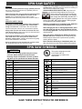
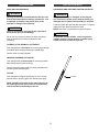
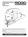
Owner’s Manual SPIN SAW / ROTARY TOOL KIT Model No. PT301H ! WARNING Always have one hand firmly placed on the tool body while operating. Never operate the tool by holding only the tool handle. CAUTION: Before using this Spin Saw/Rotary Tool, read this manual and follow all its Safety Rules and Operating Instructions. · · · · · Safety Instructions Accessories Assembly Operation Maintenance FANTOM, 178 West Service Road, Champlain, N.Y. 12919 TABLE OF CONTENTS SECTION PAGE SECTION PAGE Product Specifications …………………. Power Tool Safety ..…………………….. Spin Saw/ Rotary Tool Safety .……... Electrical Requirements & Safety …….. 2 3 4 5 Carton Contents ………………………… Know Your Spin Saw ……………….. Assembly & Operation …….…………… Maintenance …………………………….. 6, 7 8 9 – 17 17 Warranty ….....................................……. 18 ! WARNING Some dust created by power sanding, sawing, grinding, drilling and other construction activities contains chemicals known (to the State of California) to cause cancer, birth defects or other reproductive harm. Some examples of these chemicals are: · Lead from lead-based paints · Crystalline silica from bricks, cement and other masonry products · Arsenic and chromium from chemically treated lumber Your risk from these exposures varies, depending on how often you do this type of work. To reduce your exposure to these chemicals, work in a well ventilated area and work with approved safety equipment such as those dust masks that are specially designed to filter out microscopic particles. PRODUCT SPECIFICATIONS To avoid electrical hazards, fire hazards or damage to the spin saw, use proper circuit protection. This spin saw is wired at the factory for 110-120 Volt operation. It must be connected to a 110-120 Volt / 15 Ampere time delay fuse or curcuit breaker. To avoid shock or fire, replace power cord immediately if it is worn, cut or damaged in any way. Before using your spin saw, it is critical that you read and understand these safety rules. Failure to follow these rules could result in serious injury to you or damage to the spin saw. Motor Rating: 120V., 60Hz. 4.0 A. No Load Speed: 30,000 RPM Weight: 3.75 lbs. 2 Rev. 05/03 POWER TOOL SAFETY Dress properly. Do not wear loose clothing or jewelry. Contain long hair. Keep your hair, clothing and gloves away from moving parts. Loose clothing, jewelry or long hair can be caught in moving parts. GENERAL SAFETY RULES ! WARNING Read and understand all instructions. Failure to follow all instructions listed below may result in electric shock, fire and/or serious personal injury. Avoid accidental starting. Be sure switch is OFF before plugging in. Carrying tools with your finger on the switch or plugging in tools that have the switch ON invites accidents. WORK AREA Keep your work area clean and well lit. Cluttered benches and dark areas invite accidents. Remove adjusting keys or wrenches before turning the tool ON. A wrench or key that is left attached to a rotating part of the tool may result in personal injury. Do not operate power tools in explosive atmospheres, such as in the presence of flammable liquids, gasses or dust. Power tools create sparks which may ignite the dust or fumes. Do not overreach. Keep proper footing and balance at all times. Proper footing and balance enables better control of the tool in unexpected situations. Keep bystanders, children and visitors away while operating the tool. Distractions can cause you to lose control. Use safety equipment. Always wear eye protection. Dust mask, non-skid safety shoes, hard hat or hearing protection must be used for appropriate conditions. ELECTRICAL SAFETY TOOL USE AND CARE Double insulated tools are equipped with a polarized plug (one blade is wider than the other). This plug will fit in a polarized plug only one way. If the plug does not fit fully in the outlet, reverse the plug. If it still does not fit, contact a qualified electrician to install a polarized outlet. Do not change the plug in any way. Double insulation eliminates the need for the three wire grounded power cord and grounded power supply system. Use clamps or other practical way to secure and support the workpiece to a stable platform. Holding the work by hand or against your body is unstable and may lead to loss of control. Do not force the tool. Use the correct tool for your application. The correct tool will do the job better and safer at the rate for which it is designed. Avoid body contact with grounded surfaces such as pipes, radiators, ranges and refrigerators. There is increased risk of electric shock if your body is grounded. Do not use the tool if the switch does not turn it ON or OFF. Any tool that cannot be controlled with the switch is dangerous and must be repaired. Don’t expose power tools to rain or wet conditions. Water entering the power tool will increase the risk of electric shock. Disconnect the plug from the power source before making any adjustments, changing accessories or storing the tool. Such preventive safety measures reduce the risk of starting the tool accidentally. Do not abuse the cord. Never use the cord to carry the tools or pull the plug from an outlet. Keep cord away from heat, oil, sharp edges or moving parts. Replace damaged cords immediately. Damaged cords increase the risk of electric shock. Store idle tools out of reach of children and other untrained persons. Tools are dangerous in the hands of untrained users. Maintain tools with care. Keep cutting tools sharp and clean. Properly maintained cutting tools with sharp cutting edges are less likely to bind and are easier to control. When operating a power tool outside, use an outdoor extension cord marked “W-A” or “W”. These cords are rated for outdoor use and reduce the risk of electric shock. Check for misalignment or binding of moving parts, breakage of parts and any other condition that may affect the tool’s operation. If damaged, have the tool serviced before using. Many accidents are caused by poorly maintained tools. PERSONAL SAFETY Stay alert, watch what you are doing and use common sense when operating a power tool. Do not use the tool while tired or under the influence of drugs, alcohol or medication. A moment of inattention while operating power tools may result in serious personal injury. Use only accessories that are recommended by the manufacturer for your model. Accessories that may be suitable for one tool may become hazardous when used on another tool. SAVE THESE INSTRUCTIONS FOR REFERENCE 3 SPIN SAW SAFETY Always wear safety goggles and dust mask. Use only in well ventilated area. Using personal safety devices and working in a safe environment reduces risk of injury. SERVICE Tool service must be performed only by qualified personnel. Service or maintenance performed by unqualified personnel could result in risk of injury. ALWAYS WEAR EYE PROTECTION. Any power tool can throw foreign objects into your eyes which could cause permanent eye damage. ALWAYS wear safety goggles (not glasses) that comply with ANSI safety standard Z87.1. Everyday glasses have only impact resistant lenses. They ARE NOT safety glasses. Safety goggles are available at most hardware stores. Glasses or goggles not in compliance with ANSI Z87.1 could cause serious injury when they break. When servicing a tool, use only identical replacement parts. Follow instructions in the Maintenance section of this manual. Use of unauthorized parts or failure to follow Maintenance instructions may create a risk of electric shock or injury. SPECIFIC SAFETY RULES Hold tool by insulated gripping surfaces when performing an operation where the cutting tool may contact hidden wiring or its own cord. Contact with a “live” wire will make exposed metal parts of the tool “live” and shock the operator. After changing the bits or making adjustments, make sure the collet nut and any other adjustment devices are securely tightened. Loose adjustment devices will be violently thrown. Always make sure the work surface is free from nails and other foreign objects. Cutting into a nail can cause the bit and the tool to jump and damage the bit. Never hold the workpiece in one hand and the tool in the other hand when in use. Never place the hands near or below the cutting surface. Clamping the material and guiding the tool with both hands is much safer. Never use dull or damaged bits. Sharp bits must be handled with care. Damaged bits can snap during use. Dull bits require more force to push the tool, possibly causing the bit to break. Never lay workpiece on hard surfaces like concrete, stone, etc. Protruding cutting bit may cause tool to jump. Never touch the bit during or immediately after use. After use the bit is too hot to be touched by bare hands. SPIN SAW SYMBOLS ! WARNING This symbol designates that this tool is listed with U.S. requirements by Underwriters Laboratories. Some of the following symbols may be used on your tool. Please study them and learn their meaning. Proper interpretation of these symbols will allow you to operate the tool better and safer. Volts V A Hz W kW l kg N/cm2 Pa h min s hertz three-phase alternating current three-phase alternating current with neutral direct current watt no load speed kilowatts alternating or direct current microfarads class II construction liters splash proof construction kilograms watertight construction protective earthing at earthing terminal, Class I tools revolutions or reciprocations per minute Amperes newtons per square centimeter pascals hours Diameter minutes Off position seconds Arrow alternating current Warning symbol SAVE THESE INSTRUCTIONS FOR REFERENCE 4 ELECTRICAL REQUIREMENTS & SAFETY DOUBLE INSULATION GUIDELINES FOR EXTENSION CORDS Make sure your extension cord is in good condition. When using an extension cord, be sure to use one heavy enough to carry the current the tool will draw. An undersized cord will cause a drop in line voltage resulting in loss of power and overheating. The table below shows the correct size to use according to cord length and nameplate ampere rating. If in doubt, use the next heavier gauge. The smaller the gauge number the heavier the cord. This cutting tool is double insulated to protect you from electrical shock. ! WARNING Double insulated tools are equipped with a polarized plug (one blade is wider than the other). This plug will fit into a polarized outlet only one way. If the plug does not fit fully into the outlet, reverse the plug. If it still does not fit, contact a qualified electrician to install a polarized outlet. Do not alter the plug in any way. Double insulation eliminates the need for the three wire grounded power cord and grounded power supply system. Be sure your extension cord is properly wired and in good condition. Always replace a damaged extension cord or have it repaired by a qualified electrician before using it. Protect your extension cord from sharp objects, excessive heat and damp or wet areas. Avoid body contact with grounded surfaces such as pipes, radiators, ranges and refrigerators. There is an increased risk of electric shock if your body is grounded. Use a separate electrical circuit for your power tools. This circuit must not be less than 14 gauge wire and should be protected with either a 15 Ampere time delay fuse or circuit breaker. Before connecting the power tool to the power source, make sure the switch is in the OFF position and the power source is the same as indicated on the nameplate. Running at lower voltage will damage the motor. Do not expose power tools to rain or wet conditions. Water entering a power tool will increase the risk of electric shock. Do not abuse the cord. Never use the cord to carry the tool or pull the plug from the outlet. Keep cord away from heat, oil, sharp edges and moving parts. Replace damaged cords immediately. Damaged cords increase the risk of electric shock. ! Repair or replace damaged or worn extension cords immediately. When operating a power tool outdoors, use an outdoor extension cord marked “W-A” or “W”. These cords are rated for outdoor use and reduce the risk of electric shock. ! WARNING ! WARNING Keep the extension cord clear of the working area. Position the cord so it will not get caught on the workpiece, tools or any other obstructions while you are working with the power tool. WARNING Always make sure the receptacle is polarized. If you are not sure, have a qualified electrician check the receptacle. 5 ACCESSORIES CARTON CONTENTS AVAILABLE ACCESSORIES ! UNPACKING AND CHECKING CARTON CONTENTS WARNING ! Use only accessories recommended for this spin saw. Follow instructions that accompany accessories. Use of improper accessories may cause injury to the operator or damage to the spin saw. ! WARNING If any part is missing or damaged, do not plug the spin saw into the power source until the missing or damaged part is replaced and assembly is complete. Carefully unpack the spin saw and all its parts. Compare against the “Spin Saw Components” chart. NOTE: See Page 7 for illustration of parts and chart. WARNING Use only accessories designed for this spin saw to avoid severe injury or tool damage. ! WARNING To avoid fire or toxic reaction, never use gasoline, naphtha, acetone, lacquer thinner or similar highly volatile solvents to clean the spin saw. Do not use any accessory unless you have completely read the instructions or Owner’s Manual for that accessory. LATERAL STYLE DRYWALL CUTTING BIT This cutting bit has a fine spiral for removing high volumes of material when cutting and leaving a smooth edge. Use this cutter for cutting drywall. GENERAL PURPOSE CUTTING BIT This cutting bit has a coarse spiral for removing material when being used for general cutting. Use this general purpose cutter for cutting materials such as wood, plastic and fiberglass. TILE BIT Tile Bit This cutting bit is designed specifically for use in cutting wall tile and for removing grout from wall tile (see right). NOTE: DO NOT use this tile bit for cutting floor tile or for removing floor tile grout. Floor tile is harder than wall tile and will cause damage to the bit. 6 CARTON CONTENTS SPIN SAW COMPONENTS KEY A B C D E F G H I J K L M N O P Q R 7 DESCRIPTION Spin Saw Precision Handle with Sole Plate Freehand Sole Plate Attachment Circle Cutter Attachment Circle Cutter Installation Adapter Router Base Attachment 1/8” Collet 1/4” Collet 1/8” Lateral Style Drywall Cutter has "000028 HSS 1/8" marked on the shank of cutter 1/8” General Purpose Cutter has "000032" marked on the shank of cutter 1/8” Tile Bit Straight Router Bit Round Groove Router Bit Corner Round Router Bit Collet Wrench Collet Wrench Holder Owner’s Manual Carrying Case QTY 1 1 1 1 1 1 1 1 2 2 1 1 1 1 1 1 1 1 KNOW YOUR SPIN SAW 8 ASSEMBLY & OPERATION ! WARNING INSTALLING CUTTING BITS – Cont’d Remove the plug from the power source before assembly, changing accessories or cutters and making adjustments. This safety action will help prevent accidental starting of the tool which could result in serious injury. 4. Insert new cutting bit (4) into the collet. ! WARNING Insert the bit all the way into the collet and then 1 1 pull it back between /16” and /8”. This creates an air space between the motor shaft and the bit to help prevent overheating the bit. ON / OFF SWITCH This spin saw is equipped with a sliding ON / OFF switch (1) located on the top of the tool (see Fig. 1). Before tightening the collet on the bit, make sure the flutes (spiral portion) of the bit are completely visible outside the collet. Clamping the collet on the bit flutes will result in broken bits and possible injury. 5. When bit is properly placed in the collet, depress the shaft locking button and turn the collet nut clockwise by hand as far as possible. 6. Securely tighten collet nut using the wrench. Fig. 1 1. To turn the tool ON, slide the switch up. 2. To turn the tool OFF, slide the switch down. INSTALLING CUTTING BITS ! WARNING Cutting bit and router bit cutting surfaces are extremely sharp. Handle with caution. Fig. 2 To insert a cutting bit, use the collet wrench which is in the wrench holder attached to the power cord. 1. Depress the shaft locking button (1) and rotate the collet lock nut (2) clockwise with the other hand until the locking button drops into place, preventing the shaft from turning (see Fig. 2). 2. While continuing to hold the shaft locking button IN, use the collet wrench (3) to turn the collet nut counter clockwise. Loosen the collet nut 2 or three turns. 3. Remove bit if one is already installed in the tool. 9 ASSEMBLY & OPERATION CHANGING COLLET INSERT INSTALLING FREEHAND SOLE PLATE – cont’d The cutting bits for this tool are locked into place with a collet nut (1) and collet (see Fig. 3). The tool is 1 assembled at the factory with a /8” collet (2) which is used to hold the cutting bit. An additional ¼” collet (3) is supplied for holding SMALL router bits with a ¼” shank. 1. Remove accessory locking knob (1) from the base of the spin saw motor housing (see Fig. 4). Slide freehand sole plate mounting bracket (2) onto the bottom of motor housing (3) until the mounting hole (4) lines up with the hole in the motor housing. NOTE: The tab on the side of the sole plate mounting band must be inserted into the matching slot in the motor housing. 2. Re-insert accessory locking knob into the motor housing and securely tighten. Fig. 3 To change from one collet size to the other: 1. Remove bit from the tool. 2. Continue turning the collet nut counter clockwise until it can be removed from the motor shaft (4). 3. Pull the collet out of the motor shaft and replace it with the other one. NOTE: Each collet is the same on both ends, so either end can be inserted into the motor shaft. Fig. 4 4. Re-install the collet nut and slightly tighten it by hand. ADJUSTING FREEHAND SOLE PLATE 5. Install the new bit as outlined in INSTALLING CUTTING BITS on Page 9. 1. Adjust freehand sole plate depth by loosening the depth gauge knob (5) and sliding the sole plate (6) in or out as required (see Fig. 5). NOTE: Set the depth gauge so the cutting bit 1 protrudes beyond the sole plate /8” more than the thickness of the material being cut. For example, if 5 you are cutting /8” drywall, the bit should protrude ¾” beyond the sole plate. NOTE: Tightening the collet nut without a bit in the collet will cause the collet hole to become smaller and make installing bits difficult. When storing the tool with no bit installed, leave collet nut loose. 2. Securely tighten depth gauge knob. FREEHAND SOLE PLATE INSTALLING FREEHAND SOLE PLATE 3. Before starting to cut you should re-check bit depth, make sure sole plate is at right angles to the bit and securely tightened. Re-check the collet to make sure the bit is securely fastened. The freehand sole plate is designed for basic freehand cutting with the cutting bit. It is ideally suited for cutting electrical outlet holes in drywall. ! WARNING Do NOT use the freehand sole plate with router bits. Limited control with this accessory could cause you to loose control and increase the chance of serious injuy. 10 Fig. 5 ASSEMBLY & OPERATION PRACTICE CUTS USING FREEHAND SOLE PLATE WARNING ! 6. Turn the switch ON. Have you read “POWER TOOL SAFETY”, “SPIN SAW SAFETY” and “ELECTRICAL SAFETY” on pages 3, 4 and 5 of this Manual? If not, please do it now before you operate this spin saw. Your safety depends on it! 7. When the motor is up to full speed, slowly tip the tool to an upright position, letting the bit cut into the workpiece (see Fig. 7). Once the tool has reached the upright position and the bit has cut through the workpiece, slowly move the tool in a clockwise direction using slow steady pressure to make the cut. NOTE: Except for cutting around outlet boxes in drywall, always cut in a clockwise direction. Every time you use the spin saw you should verify the following: 1. Spin saw cord is not damaged. 2. Bit is correct type for the material being cut. 3. Bit is sharp, in good condition, properly installed and securely tightened. 4. Safety glasses and dust mask are being worn. 8. When cut is complete, turn the tool OFF, wait until it comes to a complete stop and remove it from the workpiece. Failure to adhere to these safety rules can greatly increase your chances of injury. PRACTICE CUTS USING FREEHAND SOLE PLATE Before attempting to work on an actual project, take the time to make a few practice cuts with your spin saw. Use some scraps of material that are the same material as used in your actual project. 1. Draw a pattern similar to your first project on a scrap piece of material. Fig. 7 ! 2. Install freehand sole plate as shown in Fig. 4. Do not attempt cutting around outlet boxes in drywall until: 1. All electricity in the vicinity of electric wires has been disconnected by either turning the breaker OFF or removing the fuses. 3. Install cutting bit in the collet as shown in Fig. 2. 4. Adjust depth of freehand sole plate as shown in Fig. 5. 5. Rest the edge of the sole plate on the workpiece with o the bit at an angle of about 45 (see Fig. 6). NOTE: DO NOT let the bit contact the workpiece until switch is turned ON and the tool is up to full speed. ! DANGER 2. You have read the instructions on the following page entitled “CUTTING OUTLET OPENINGS IN DRYWALL”. WARNING CUTTING TIPS Before turning the tool switch ON, make sure you hold the tool firmly with both hands. Starting torque will cause the tool to twist. The rotating cutting action of the bit will cause a slight pull to the left when cutting. Natural variations in the structure of wood will cause the bit to “wander”. This tendency will be magnified when applying too much pressure to the bit. Slower cutting gives you better control. Excessive pressure or fast cutting will increase bit temperature and shorten the life of the bit. When cutting a hole in a vertical surface, avoid ending the cut at the bottom of the hole. Always start and end the cut at the “top” so the cut-out part will not drop onto the rotating bit. Always turn the tool OFF before removing it from the workpiece. Fig. 6 11 ASSEMBLY & OPERATION CUTTING OUTLET OPENINGS IN DRYWALL – cont’d CUTTING OUTLET OPENINGS IN DRYWALL ! 6. Move the bit slowly to the right until you feel and hear the bit contacting the inside of the box. DANGER Do not attempt to use this tool to make cut-outs around any fixture or opening which has live electrical wires or on any wall which may have electrical wiring behind it. If a live wire is contacted, the bit could conduct the electric current to the tool, creating an electrocution hazard for the operator. Turn OFF breakers or remove fuses to disconnect the electric circuit in the area of work. Always hold the tool by its insulated housing when working in areas where there is a possibility of contacting electric wires. Always wear eye protection when operating this tool. 7. Pull the bit out far enough to slip it over the edge of the box. Once the bit is outside the box, push it back to full depth beside the outside edge of he box. 8. Move the tool upward while applying slight pressure toward the center of the box. When you feel the bit reach the top right hand corner of the box, move the tool to the left while applying slight pressure downward toward the center of the box. 1. Before installing drywall, push the electrical wires to the back of the box as far as possible so they will not be cut by the bit when cutting the opening. 9. Continue moving the tool around the box in a counter clockwise direction while maintaining slight pressure toward the center of the box. When the box cut-out is complete. Turn the tool OFF and remove it from the cut-out. 2. Before fastening the drywall sheet over the electrical box, mark the sheet as close as possible to the center of the box opening. Mark should be on the side of the drywall facing you. 10. Completed electrical box cut-out will be accurately and neatly cut (see Fig. 9). 3. When fastening the drywall in place, do not place nails or screws closer than 12” from the box. This will prevent the drywall from becoming deformed under pressure. 4. Insert cutting bit and install freehand sole plate as outlined on Pages 9 & 10 of this Owner’s Manual. 1 Adjust dept of cut so the bit will protrude /8” beyond the thickness of the drywall. 5. Hold the tool firmly with both hands and turn it ON. Plunge the bit through the drywall at the mark indicating the center of the box. See Fig. 8 for cutting pattern. Fig. 9 NOTE: Always move the cutting bit in a counter clockwise direction around the outlet box. The natural tendency of the cutting bit to move to the left will make it easier to cut close to the box. Fig. 8 12 ASSEMBLY & OPERATION ADJUSTING FREEHAND SOLE PLATE – Cont’d PRECISION HANDLE INSTALLING PRECISION HANDLE The precision handle is designed for use when precision control over the tool movement is desired. The comfortable handle can be used with either the right or left hand. Fig. 11 1. Remove accessory locking knob (1) from the base of the spin saw motor housing (see Fig. 10). Slide precision handle mounting bracket (2) onto the bottom of motor housing (3) until the mounting hole (4) lines up with the hole in the motor housing. NOTE: The tab on the side of the precision handle mounting bracket must be inserted into the matching slot in the motor housing. CIRCLE CUTTER INSTALLING CIRCLE CUTTER The circle cutter accessory is ideal for precision cutting of circles. This circle cutter can be attached to either the freehand sole plate or the precision handle sole plate. For purposes of illustration, the circle cutter is shown with the freehand sole plate. 2. Re-insert accessory locking knob into the motor housing and securely tighten. 1. Install freehand sole plate on the tool as illustrated on Page 10 of this Owner’s Manual. 2. Insert the externally threaded circle cutter mounting insert (1) into the bottom of the sole plate (2) (see Fig. 12). NOTE: Make sure the “D” shaped opening in the mounting insert is inserted into the matching “D” shaped opening in the sole plate. 3. Place circle cutter mounting hole (3) over the externally threaded circle cutter mounting insert. NOTE: Make sure pointed pivot pin (4) is pointing away from the tool. 4. Screw the internally threaded circle cutter mounting disc (5) onto the externally threaded circle cutter mounting insert and hand tighten. NOTE: Do not over tighten the circle cutter mounting plastic parts. Hand tighten only. Fig. 10 ADJUSTING FREEHAND SOLE PLATE 5. Adjust the circle cutting radius by loosening pivot point knob (6), sliding it to the correct circle radius and retightening in the desired location. NOTE: Check circle cutter radius setting by measuring from the pivot point to the outside of the cutting bit. 1. Adjust precision handle sole plate depth, by loosening the depth gauge knob (5) and sliding the sole plate (6) in or out as required (see Fig. 11). NOTE: Set the depth gauge so the cutting bit 1 protrudes beyond the sole plate /8” more than the thickness of the material being cut. For example, if 3 7 you are cutting /4” pine, the bit should protrude /8” beyond the sole plate. 2. Securely tighten depth gauge knob. 3. Before starting to cut you should re-check bit depth, make sure sole plate is at right angles to the bit and securely tightened. Re-check the collet to make sure the bit is securely fastened. 13 Fig. 12 ASSEMBLY & OPERATION CIRCLE CUTTER CIRCLE CUTTER OPERATION – cont’d CIRCLE CUTTER OPERATION ! 5. Turn the switch ON. WARNING Unplug the tool from the power source before changing accessories, changing bits and making adjustments. 6. When the motor is up to full speed, slowly tip the tool and circle cutter assembly to an upright position, letting the bit cut into the workpiece (see Fig. 14). Be careful to keep the pivot point located at the center of the circle to be cut. Once the tool has reached the upright position and the bit has cut through the workpiece, slowly move the tool in a clockwise direction using slow steady pressure to make the cut. Continue to cut the circle, keeping the tool upright and rotating around the circle cutter pivot point. Before turning the tool ON, check to make sure bit and all accessory fasteners are securely tightened. 1. Mark the center of the circle you wish to cut on the 15 workpiece and drill a 6 mm or /64” pilot hole. 1 2. Adjust cutting bit depth to /8” longer that the thickness of the material being cut. 7. When cut is complete, turn the tool OFF, wait until it comes to a complete stop and remove it from the workpiece. 3. Adjust the circle cutting radius by loosening pivot point knob, sliding it to the correct circle radius and retightening in the desired location. NOTE: Check circle cutter radius setting by measuring from the pivot point to the outside of the spiral bit. 4. Rest the edge of the sole plate on the workpiece with 0 the bit at an angle of about 45 (see Fig. 13). Insert the circle cutter pivot point into the pilot hole drilled at the center of the circle. NOTE: DO NOT let the bit contact the workpiece before switch is turned ON and the tool is up to full speed. Fig. 14 Fig. 13 14 ASSEMBLY & OPERATION SETTING ROUTER DEPTH ROUTER BASE The router accessory converts your spin saw into a small hobby router that is capable of handling small ¼” shank router bits as well as the spiral cutting bit. The tilting base is ideal for bevel cutting. ! Depth of cutting is controlled by sliding the router base up and down in the adjusting sleeves. 1. Loosen both height adjusting knobs (1) by turning them counter clockwise (see Fig. 16). WARNING 2. Slide router base (2) up or down to obtain the desired depth of cut. Unplug the tool from the power source before changing accessories, changing bits and making adjustments. 3. Re-tighten height adjusting knobs when the desired cut depth is reached. Before turning the tool ON, check to make sure the bit and all accessory fasteners are securely tightened. ROUTER ACCESSORY INSTALLATION 1. Remove any accessory already installed on the tool. 2. Remove accessory locking knob (1) from the base of the spin saw motor housing (see Fig. 15). Depress the motor shaft locking button (2) on the back of the motor housing (see inset). NOTE: Rotate the collet nut while holding down on the motor shaft locking button until the button drops into the hole in the motor shaft. Fig. 16 3. Slide router accessory mounting bracket (3) onto the bottom of motor housing (4) until the mounting hole (5) lines up with the hole in the mounting bracket. SETTING ROUTER BASE BEVEL Bevel cutting with the cutting bit can be done with the router base tilted to the desired angle. NOTES: The raised hole in the mounting bracket will slide over the motor shaft locking button only if the button is fully depressed and engaged in the motor shaft. 1. Loosen both bevel adjusting knobs (3) by turning them counter clockwise at least 2 turns (see Fig. 17). 2. Tilt router base (2) to the desired angle. The tab on the reverse side of the router base mounting band must be inserted into the matching slot in the motor housing. 3. Re-tighten both height adjusting knobs. 4. Check bevel angle between router base and spiral cutter to ensure they are at correct angle. 4. Re-insert accessory locking knob into the motor housing and securely tighten. 5. Check router depth of cut and re-set the depth if required. NOTE: Depth of cut will usually have to be increased after tilting the router base for bevel cutting. Fig. 15 15 Fig. 17 ASSEMBLY & OPERATION ROUTER BASE FREEHAND CUTTING AND ROUTING CUTTING STRAIGHT LINE WITH STRAIGHT EDGE When the router base accessory is installed on the spin saw, it will function as a small router to be used for freehand cutting of irregular shaped patterns. You can cut patterns out of the workpiece with the cutting bit or route patterns into the workpiece with small router bits. To cut a straight line, you can use a straight edge template to guide the router base. FREEHAND CUTTING 2. Draw a parallel second line approximately 2 /8” back into the workpiece (away from the cutting line). 1. Draw a line on the workpiece where you wish to make the cut (see Fig. 19). 1 1 1. Adjust the cutting bit depth to /8” longer than the thickness of the material being cut. 3. Clamp the straight edge onto the larger portion of the workpiece that is to be clamped while cutting. 2. Turn the switch ON while firmly holding the tool. 4. Place the flat side of the router base against the straight edge with the bit near the start of the cutting line. NOTE: Check bit location to ensure cut will be made in the correct location. 3. When starting the cut inside the workpiece, place the bit at an angle to allow the bit to cut its way into the workpiece (see Page 11 Fig. 6). 4. Use the two height adjusting knobs to guide the bit through the workpiece. 5. Turn the switch ON while firmly holding the tool. 6. Slide the router plate against the straight edge while making the cut. FREEHAND ROUTING Use the router base with small router bits to perform various freehand routing projects (see Fig. 18). 1 1. Remove /8” collet and insert ¼” collet (see Page 10 Fig. 3). 2. Install router bit and securely tighten. 3. Adjust router base height to the correct routing depth. 4. Turn the switch ON making sure the router bit is not touching anything. 5. Holding the tool by the two height adjusting knobs, carefully lower the bit onto the workpiece and guide the bit around the desired pattern. Fig. 19 Fig. 18 16 OPERATION & MAINTENANCE MAINTENANCE ROUTER BASE EXTERNAL CLEANING CUTTING CURVED LINE WITH A TEMPLATE To cut a curved line, you can use a curved template to guide the router base. ! WARNING DO NOT use solvents when cleaning plastic parts. Most plastics are susceptible to damage from various types of commercial solvents and may be damaged by their use. Use clean cloth to remove dirt, dust, oil, grease, etc. 1. Make a template from hardboard or other similar material to the shape you require (see Fig. 20). NOTE: Radius of curve must be greater than 2 ½” for router base to properly follow the curved template. Do not at any time allow brake fluids, gasoline, petroleum-based products, penetrating oils, etc. to come in contact with plastic parts. They contain chemicals that can damage, weaken or destroy plastic. 2. Mark the location of the cut to be made. 7 3. Mark the workpiece approximately 2 /16” back into the workpiece (away from the cutting line). 4. Clamp the template onto the larger portion of the workpiece that is to be clamped while cutting. INTERNAL CLEANING It has been found that electric tools are subjected to accelerated wear and possible premature failure when they are used on fiberglass boats and sports cars, wallboard, spackling compounds or plaster. The chips and grindings from these materials are highly abrasive to electric tool parts such as bearings, brushes, commutators, etc. During any use on these materials it is extremely important that the tool is cleaned frequently by blowing out with a compressed air jet. 5. Place the curved portion of the router base against the template with the bit near the start of the cutting line. NOTE: Check bit location to ensure cut will be made in the correct location. 6. Turn the switch ON while firmly holding the tool. 7. Slide the router plate against the template while making the cut. ! DANGER It is critical that you wear safety goggles or safety glasses with side shields and a dust mask while blowing dust out of the spin saw with a compressed air jet. Failure to take these safety precautions could result in permanent eye or lung damage. POWER CORD MAINTENANCE ! WARNING To avoid shock or fire hazard, replace the cord immediately if it is worn or damaged in any way. Fig. 20 GENERAL LUBRICATION MAINTENANCE All of the bearings in this spin saw are lubricated with a sufficient amount of high grade lubricant for the life of the unit under normal conditions. Therefore, no further lubrication is required ! DANGER For your own safety, turn the switch OFF and remove the plug from the power source before maintaining your spin saw. When servicing, use only identical original equipment parts. Use of any other part may create a hazard or cause product damage. 17 Model PT301H TWO (2) YEAR LIMITED WARRANTY FANTOM warrants this product to be free from defects in material and workmanship for a period of two (2) years from the date of the original purchase, when utilized for normal household use, subject to the following conditions, exclusions and exceptions. If your appliance fails to operate properly while in use under normal household conditions within the warranty period, return the complete appliance and accessories, freight prepaid to FANTOM, 178 W. Service Rd. Champlain, NY 12919. If the appliance is found by FANTOM to be defective in material or workmanship, FANTOM will repair or replace it free of charge. Proof of purchase date and $ 14.95 to cover the cost of return shipping and handling must be included. * Non-durable parts including, without limitation, router bits, cutting bits, drill bits, carbon brushes and electrical parts which normally require replacement are specifically excluded from warranty. The liability of FANTOM is limited solely to the cost of the repair or replacement of the unit at our option. This warranty does not cover normal wear of parts and does not apply to any unit that has been tampered with or used for commercial purposes. This limited warranty does not cover damage caused by misuse, abuse, negligent handling or damage due to faulty packaging or mishandling in transit. This warranty does not cover damage or defects caused by or resulting from damages from shipping or repairs, service or alterations to the product or any of its parts, which have been performed by a repair person not authorized by FANTOM. This warranty is extended to the original purchaser of the unit and excludes all other legal and/or conventional warranties. The responsibility of FANTOM if any, is limited to the specific obligations expressly assumed by it under the terms of the limited warranty. In no event is FANTOM liable for incidental or consequential damages of any nature whatsoever. Some states do not permit the exclusion or limitation of incidental or consequential damages, so the above may not apply to you. This warranty gives you specific legal rights, and you may also have other rights which vary from state to state. *Important: Carefully pack item to avoid damage in shipping. Be sure to include proof of purchase date and to attach tag to item before packing with your name, complete address and phone number with a note giving purchase information, model number and what you believe is the problem with item. We recommend you insure the package (as damage in shipping is not covered by your warranty). Mark the outside of your package “ATTENTION CUSTOMER SERVICE”. We are constantly striving to improve our products, therefore the specifications contained herein are subject to change without notice. $ OWNERSHIP REGISTRATION CARD Please fill out and mail the product registration card within ten (10) days of purchase in order to validate the foregoing Limited Warranty. The registration will enable us to contact you in the unlikely event of a product safety notification. By returning this card you acknowledge to have read and understood the instructions for use, and warnings set forth in the accompanying instructions. RETURN TO FANTOM: 178 W. Service Rd. Champlain, NY 12919 _______________________________________________________________________ Model PT301H Appliance model ______________________________________________________________________________ Date purchased Name of store ________________________________________________________________________________ Owner’s name ________________________________________________________________________________ Address City State Zip Code Printed in China