1
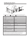
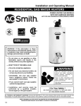
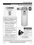
! Warning: This water heater is not suitable
for use in manufactured (mobile) homes!
Use & Care Manual
With Installation Instructions for the Installer
Residential Gas - FVIR
Certified
High Efficiency Condensing Power Direct Vent
Water Heaters
Residential 38 and 48 Gallon
The purpose of this manual is twofold: one, to provide the installer with the basic directions
and recommendations for the proper installation and adjustment of the water heater; and two,
for the owner–operator, to explain the features, operation, safety precautions, maintenance and
troubleshooting of the water heater. This manual also includes a parts list.
It is very important that all persons who are expected to install, operate or adjust this water
heater read the instructions carefully so they may understand how to perform these operations.
If you do not understand these instructions or any terms within it, seek professional assistance.
Any questions regarding the operation, maintenance, service or warranty of this water heater
should be directed to the seller from whom it was purchased. If additional information is
required, refer to the section on “If you need service.”
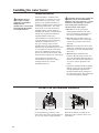
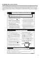
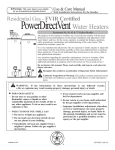
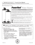
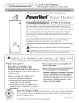
SCALD RISK INCREASES
WITH HOTTER WATER
To review or adjust tempture
Step 1. Press the two temperature adjust buttons at the same time for 1 second.
Step 2. To adjust, press COOLER or HOTTER button for desired temperature.
EMMERSON
!
Do not destroy this manual. Please read carefully and keep in a safe place for future
reference.
Recognize this symbol as an indication of Important Safety Information!
!
ARNING: If the information in these instructions is not followed exactly,
W
a fire or explosion may result causing property damage, personal injury or death.
! FOR
YOUR SAFETY!
— Do not store or use gasoline or other
flammable vapours or liquids or other
combustible materials in the vicinity of this or
any other appliance. To do so may result in an
explosion or fire.
— WHAT TO DO IF YOU SMELL GAS
● Do not try to light any appliance.
● Do not touch any electrical switch; do not
use any phone in your building.
● Immediately call your gas supplier from
a neighbour’s phone. Follow the gas
supplier’s instructions.
● I f you cannot reach your gas supplier, call
the fire department.
●D
o not return to your home until authorized
by the gas supplier or fire department.
— I mproper installation, adjustment, alteration,
service or maintenance can cause property
damage, personal injury, or death. Refer to
this manual. Installation and service must be
performed by a qualified installer, service
agency or the gas supplier.
Printed in USA
AP16566 (06/12)
Safety Information
Safety Precautions. . . . . . 3–6
LP Gas Models. . . . . . . . . . . . 5
Installation Instructions
Location. . . . . . . . . . . . . . . . . . 7
Water Supply
Connections . . . . . . . . . . . . . . 9
Condensate
Management. . . . . . . . . . . . 10
Gas Supply. . . . . . . . . . . . . . 11
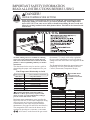
FOR YOUR RECORDS
Write the model and serial numbers here:
#
#
You can find them on a label on the appliance.
Staple sales slip or cancelled check here.
Proof of the original purchase date is needed to obtain service under
the warranty.
Vent and Combustion
Air Inlet . . . . . . . . . . . . . 12-20
Wiring Diagram. . . . . . . . . . 21
Pipe Insulation. . . . . . . . 22,23
Heat Traps . . . . . . . . . . . . . . 23
Installation Checklist . . . . . 25
Potable/Space Heating. . . 26
Operating Instructions
READ THIS MANUAL
Inside you will find many helpful hints on how to use and maintain
your water heater properly. A little preventive care on your part can
save you time and money over the life of your water heater.
You’ll find many answers to common problems in the
Troubleshooting Guide. If you review the chart of Troubleshooting
Tips first, you may not need to call for service.
Lighting Instructions . . . . 27
Water Temperature. . . . 28, 29
READ THE SAFETY INFORMATION
Your safety and the safety of others are very important.
There are many important safety messages in this manual
and on your appliance. Always read and obey all safety
messages.
Care and Cleaning
Draining . . . . . . . . . . . . . . . 31
Maintenance. . . . . . . . . . . . 31
This is the safety alert symbol. Recognize this
symbol as an indication of Important Safety
Information!
This symbol alerts you to potential hazards that
can kill or hurt you and others.
All safety messages will follow the safety alert symbol and
either the word “DANGER”, “WARNING”, “CAUTION”
or “NOTICE”.
These words mean:
!
Burner Inspection. . . . . . . 32
Vent System Inspection . . 32
Extended Shut-Down. . . . . 32
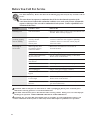
Troubleshooting Tips
Before You Call
For Service. . . . . . . . . . 33, 34
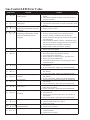
Gas Control LED Error
Codes. . . . . . . . . . . . . . . . . . . 35
!
DANGER: Customer Service
!
WARNING: A potentially hazardous situation that
!
CAUTION: A potentially hazardous situation that
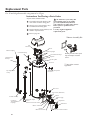
Parts List. . . . . . . . . . . . . . . 36
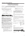
Alternate Vent Termination
Instructions. . . . . . . . . . . 37, 38
If You Need Service. . . . . . . 40
n imminently hazardous situation
A
that will result in death or serious
injury.
could result in death or serious injury
and/or damage to property.
may result in minor or moderate
injury.
Notice: Attention is called to observe a
specified procedure or maintain a
specific condition.
2
IMPORTANT SAFETY INFORMATION
READ ALL INSTRUCTIONS BEFORE USING
Be sure to read and understand the entire Use and Care Manual before attempting to install or operate
this water heater. It may save you time and money. Pay particular attention to the Safety Instructions.
Failure to follow these warnings could result in serious bodily injury or death. Should you have problems
understanding the instructions in this manual, or have any questions, STOP, and get help from a qualified
service technician, or the local gas utility.
NOTICE: This water heater is equipped with a flammable vapour sensor that will automatically shut
down the water heater in the presence of gasoline vapours and some other flammable vapours. If the
flammable vapour sensor shuts down the water heater, contact a qualified service technician. Clear
any hazardous materials and ventilate the area around the water heater. Do not turn off the appliance
or adjust the ON/OFF switch in any way. Do not tamper with the flammable vapour sensor. Do not
submerse the flammable vapour sensor in water. Do not allow the flammable vapour sensor to come into
contact with any substances such as bleach or cleaners. See the “Gas Control LED Error Codes” Section
of this manual for a list of error codes.
DANGER!
properly vent the water heater
Failure to properly vent the water heater as outlined in the Vent and Combustion Air-Inlet
Section of the Installation Instructions in this manual can result in unsafe operation of the
water heater. To avoid the risk of fire, explosion, or asphyxiation from carbon monoxide,
never operate this water heater unless both the vent and combustion air-inlet systems are
properly installed. Be sure to inspect both the vent and the combustion air-inlet for proper
installation at initial start-up; and at least periodically thereafter. Refer to the Care and
Cleaning section of this manual for more information regarding vent and combustion air-inlet
system inspection.
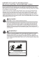
WARNING!
Gasoline, as well as other flammable materials and liquids (which include but are not limited
to adhesives, solvents, paint thinners etc.), and the vapours they produce are extremely
dangerous. DO NOT handle, use or store gasoline or other flammable or combustible
materials anywhere near or in the vicinity of a water heater or any other appliance. Be sure
to read and follow warning label pictured below and other labels on the water heater, as well
as the warnings printed in this manual. Failure to do so can result in property damage, bodily
injury or death.
!
FLAMMABLES
WARNING
Flammable Vapors
FIRE AND EXPLOSION HAZARD
!
Can result in serious injury or death.
Do not store or use gasoline or other flammable vapors and liquids
in the vicinity of this or any other appliance. Storage of or use of gasoline
or other flammable vapors or liquids in the vicinity of this or any other
appliance can result in serious injury or death.
3
IMPORTANT SAFETY INFORMATION
READ ALL INSTRUCTIONS BEFORE USING
! DANGER!
water temperature Setting
Safety and energy conservation are factors to be considered when selecting the water
temperature setting of a water heater’s gas control (thermostat). Water temperatures
above 125°F (52°C) can cause severe burns or death from scalding. Be sure to read and
follow the warnings outlined on the label pictured below. This label is also located on the
water heater.
(52°C)
Notice: Mixing valves are available for reducing
point of use water temperature by mixing hot and
cold water in branch water lines. Contact a licensed
plumber or the local plumbing authority for further
information.
The chart shown below may be used as a guide in
determining the proper water temperature for your
home.
Time/Temperature Relationship in Scalds
Water Temperature
120°F (49°C)
125°F (52°C)
130°F (54°C)
135°F (57°C)
140°F (60°C)
145°F (63°C)
150°F (66°C)
155°F (68°C)
Time To Produce a Serious Burn
More than 5 minutes
11/2 to 2 minutes
About 30 seconds
About 10 seconds
Less than 5 seconds
Less than 3 seconds
About 11/2 seconds
About 1 second
Table courtesy of Shriners Burn Institute
DANGER: Households with small children,
disabled, or elderly persons may require a 120°F
(49°C) or lower gas control (thermostat) setting to
prevent contact with “HOT” water.
!
Maximum water temperatures occur just after the
burner has shut off. To find water temperature being
delivered, turn on a hot water faucet and place
a thermometer in the water stream and read the
thermometer. (See page 28 and 29 for more details.)
The temperature of the water in the heater can be
regulated by pressing the "COOLER" or "HOTTER"
arrow buttons on the front of the gas control
4
(thermostat). To comply with safety regulations
the gas control (thermostat) was set at its lowest
setting before the water heater was shipped from the
factory.
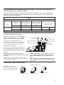
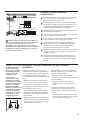
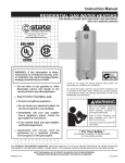
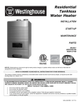
The illustration below shows the approximate water
temperature for each LED Indicator on the Gas
Control (Thermostat) Temperature Display.
A
VAC
COOLER
B
! DANGER: Hotter
water increases the
potential for Hot Water
SCALDS.
C
HOTTER
SCALDING RISK INCREASES
WITH HOTTER WATER
Display
Temperature Setting
VAC
VAC = approx. 70°F (21°C)
• = approx. 110°F (43°C)
Both • and ▲ = approx. 115°F (46°C)
▲= approx. 120°F (49°C)
Both ▲and A= approx. 125°F (52°C)
A = approx. 130°F (54°C)
Both A and B = approx. 135°F (57°C)
B = approx. 140°F (60°C)
Both B and C = approx. 145°F (63°C)
C = approx. 150°F (66°C)
C-Flashing = approx. 160°F (68°C)
▲ABC
●○○○○○
○●○○○○
○●●○○○
○○●○○○
○○●●○○
○○○●○○
○○○●●○
○○○○●○
○○○○●●
○○○○○●
○○○○○●
Burns on Adult Skin
-------------------More than 5 minutes
More than 5 minutes
More than 5 minutes
1-1/2 to 2 minutes
About 30 seconds
About 10 seconds
Less than 5 seconds
Less than 3 seconds
About 1-1/2 seconds
About 1/2 seconds
DANGER!
liquefied petroleum (LP Propane or butane)
and Natural gas models
LP and Natural gas have an odorant added to aid in detecting a gas leak. Some people
may not physically be able to smell or recognize this odorant. If you are unsure or
unfamiliar with the smell of LP or natural gas, ask the gas supplier. Other conditions,
such as “odorant fade”, which causes the odorant to diminish in intensity, can also hide or
camouflage a gas leak.
● Water heaters utilizing LP gas are
different from natural gas models. A
natural gas water heater will not function
safely on LP gas and vice versa.
●N
o attempt should ever be made to
convert the water heater from natural
gas to LP gas. To avoid possible
equipment damage, personal injury or
fire, do not connect the water heater to a
fuel type not in accordance with the unit
data plate. LP for LP units. Natural gas
for natural gas units. These units are not
certified for any other fuel type.
●L
P appliances should not be installed
below grade (for example, in a basement)
if such installation is prohibited by
federal, province and/or local laws, rules
or regulations.
●L
P gas must be used with great caution.
It is heavier than air and will collect first
in lower areas making it hard to detect at
nose level.
! DANGER: If a gas leak is present or
suspected:
● Do not attempt to find the cause
yourself.
● Do not try to light any appliance.
● Do not touch any electrical switch.
● Do not use any phone in your building.
● Leave the house immediately and make
sure your family and pets leave also.
● Leave the doors open for ventilation
and contact the gas supplier, a qualified
service agency or the fire department.
● Stay away from the house (or building)
until the service call has been made, the
leak is corrected and a qualified agency
has determined the area to be safe.
●B
efore attempting to light the water
heater, make sure to look and smell for
gas leaks. Use a soapy solution to check
all gas fittings and connections. Bubbling
at a connection indicates a leak that must
be corrected. When smelling to detect a
gas leak, be sure to sniff near the floor
also.
●G
as detectors are recommended in LP
& natural gas applications and their
installation should be in accordance
with the detector manufacturer’s
recommendations and/or local laws, rules
or regulations.
● I t is recommended that more than one
method, such as soapy solution, gas
detectors, etc., be used to detect leaks in
gas applications.
5
IMPORTANT SAFETY INFORMATION
READ ALL INSTRUCTIONS BEFORE USING
!
WARNING!
For your safety, the information in this manual must be followed to minimize the risk of
fire or explosion, electric shock, or to prevent property damage, personal injury, or loss of
life.
SAFETY PRECAUTIONS
Have the installer show you the location of the gas shut-off valve and how to shut it off
if necessary. Turn off the manual shut-off valve if the water heater has been subjected to
overheating, fire, flood, physical damage or if the gas supply fails to shut off.
● Read this manual entirely before installing
or operating the water heater.
● Use this appliance only for its intended
purpose as described in this Use and Care
Manual.
●D
O NOT attempt to repair or replace
any part of your water heater unless it is
specifically recommended in this manual.
All other servicing should be referred to a
qualified technician.
● Be sure your appliance is properly installed
in accordance with local codes and the
provided installation instructions.
Read and follow this Safety Information
carefully.
SAVE THESE INSTRUCTIONS
IMPORTANT
Carefully inspect the water heater for damage before proceeding with the installation.
If you find damage to the condensate trap, PVC pipes, gas control (thermostat) or the
blower assembly, DO NOT install or attempt any repair to the water heater. Contact the
manufacturer as detailed under "IF YOU NEED SERVICE" section of this manual.
6
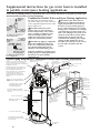
Installing the water heater
This water heater must be installed in accordance with these instructions, local codes, utility
company requirements, and/or in the absence of local codes, use the latest edition of CAN/
CSA B149.1 - Natural Gas and Propane Installation Code. A copy can be purchased from the
Canadian Standards Association, 5060 Spectrum Way, Mississauga, Ontario L4W 5N6.
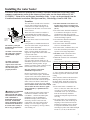
Location
The water heater should not be located in
an area where leakage from the tank or
connections will result in damage to the
area adjacent to the heater or to lower floors
of the structure.
Max.
2.75”
(7cm)
Flammable
Vapour
Sensor
When such areas cannot be avoided it is
recommended that a suitable catch pan,
adequately drained, must be installed under
the water heater.
Diameter of water
heater plus 2”
(5cm) min.
The auxiliary catch pan
installation MUST conform
to local codes.
Notice: DO NOT allow
the catch pan to obstruct
the flammable vapour
sensor.
Notice: DO NOT
allow the flammable
vapour sensor to become
submerged in water. Make
sure the catch pan is
properly drained.
! WARNING: Combustible
construction refers to
adjacent walls and ceilings
and should not be confused
with combustible or
flammable products and
materials. Combustible
and/or flammable products
and materials should never
be stored in the vicinity of
this or any gas appliance.
The water heater must be centered in the
catch pan.
Catch pan kits are available from the store
where the water heater was purchased, or
any water heater distributor.
Make certain the floor underneath the water
heater is strong enough to sufficiently
support the weight of the water heater once
it is filled with water.
A gas fired water heater or any other
appliance should not be installed
in a space where liquids which give off
flammable vapours are to be used or stored.
Such liquids include gasoline, LP gas
(butane or propane), paint or adhesives and
their thinners, solvents or removers.
●D
o not install the water heater in a
location where it may be subjected to
ambient temperatures exceeding 125°F
(52°C).
● The water heater should be installed so
as to minimize the length of vent and
combustion air-inlet pipe(s) and the
number of vent and combination air-inlet
connection fittings required.
● Hot water lines should be insulated to
conserve water and energy.
● The water heater should be installed
close to a condensate drain.
● The water heater, condensate lines, and
water lines should be protected from
exposure to freezing temperatures.
●D
O NOT install water heater where
prohibited by CAN/CSA B149.1.
●M
inimum clearance from combustible
construction:
* "Front" clearance dimension is measured
Front*
Side
Rear
Top**
0"
(0 cm)
0"
(0 cm)
0”
(0 cm)
12”
(30.5 cm)
DO NOT obstruct or block the
Flammable Vapour Sensor.
from front of the control to the closet door.
Because of natural air movement in a
room or other enclosed space, flammable
vapours can be carried some distance from
where liquids which give off flammable
vapours are to be used or stored. The open
flame of the water heater’s main burner
can ignite these vapours and create a shut
down condition of the water heater which
will not allow the water heater to ignite
until examined by a Qualified Service
Technician.
If the clearances stated on the Instruction/
Warning Label, located on the front of
the heater differ, install the water heater
according to the clearances stated on the
label.
FVIR certified gas water heaters must be
installed in accordance with the CAN/
CSA B149.1 - Natural Gas and Propane
Installation Code, for installation in
Residential Garages, unless otherwise
directed by Province and Local code
requirements. The water heater must be
located so it is not subject to physical
damage, for example, by moving vehicles,
area flooding, etc.
** "Top" clearance dimension is measured
from the top pan of the water heater to the
ceiling.
● I f the water heater is installed in an
alcove or closet, the entire floor must be
covered by a wood or metal panel.
A minimum of 24” (61 cm) clearance
from the front and top should be
available for adequate inspection and
servicing.
● The water heater may be installed on
combustible floors, but not directly on
carpeting. If the water heater must be
installed on carpeting, place a metal or
wood panel beneath the water heater,
extending beyond its full width and depth
at least 3” (7.6 cm) in all directions.
7
Installing the water heater
Corrosive Atmospheres
NOTICE: The water heater
should not be installed near
an air supply containing
halogenated hydrocarbons.
The air in beauty shops, dry cleaning
establishments, photo processing
labs, and storage areas for liquid and
powdered bleaches or swimming pool
chemicals often contain such halogenated
hydrocarbons.
will shorten the life of any gas burning
appliance.
An air supply containing halogenated
hydrocarbons may be safe to breathe,
but when it passes through a gas flame
corrosive elements are released that
The water heater warranty is voided
when failure of the water heater is due to
operation in a corrosive atmosphere.
Propellants from common spray cans
or gas leaks from A/C and refrigeration
equipment are highly corrosive after
passing through a flame.
Thermal Expansion
Determine if a check valve exists in the
inlet water line. Check with your local
water utility company. It may have
been installed in the cold water line as a
separate back flow preventer, or it may
be part of a pressure reducing valve,
water meter or water softener. A check
valve located in the cold water inlet
line can cause what is referred to as a
“closed water system”. A cold water
inlet line with no check valve or back
flow prevention device is referred to as an
“open” water system.
As water is heated, it expands in volume
and creates an increase in the pressure
within the water system. This action is
referred to as “thermal expansion”. In
an “open” water system, expanding water
which exceeds the capacity of the water
heater flows back into the city main where
the pressure is easily dissipated.
A “closed water system”, however,
prevents the expanding water from
flowing back into the main supply line,
and the result of “thermal expansion”
can create a rapid and dangerous pressure
increase in the water heater and system
8
piping. This rapid pressure increase can
quickly reach the safety setting of the
relief valve, causing it to operate during
each heating cycle. Thermal expansion,
and the resulting rapid, and repeated
expansion and contraction of components
in the water heater and piping system can
cause premature failure of the relief valve,
and possibly the heater itself. Replacing
the relief valve will not correct the
problem!
The suggested method of controlling
thermal expansion is to install an
expansion tank in the cold water line
between the water heater and the check
valve (see illustration on right). The
expansion tank is designed with an
air cushion built in that compresses as
the system pressure increases, thereby
relieving the over pressure condition and
eliminating the repeated operation of the
relief valve. Other methods of controlling
thermal expansion are also available.
Contact your installing contractor, water
supplier or plumbing inspector for
additional information regarding this
subject.
IMPORTANT: Do not apply
heat to the HOT or COLD
water connections. If sweat
connections are used, sweat
tubing to adapter before
fitting adapter to the cold
water connections on heater.
Any heat applied to the cold
water supply fittings will
permanently damage the
dip tube and heat traps.
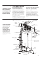
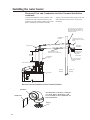
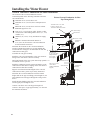
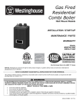
Water Supply Connections
Refer to the illustration below for
suggested typical installation. The
installation of unions or flexible copper
connectors is recommended on the hot
and cold water connections so that the
water heater may be easily disconnected
for servicing if necessary. The HOT and
COLD water connections are clearly
marked and are 3/4” NPT on all models.
Install a shut-off valve in the cold water
line near the water heater.
IMPORTANT: It is recommended that the
hot and cold water piping have a minimum
vertical height of 10" (25.4 cm) from the
top of the water heater before the transition
into any elbow. This vertical height is
needed in order to provide adequate
clearance for top cap installation and
removal.
To gain access to the hot and cold water
connections on water heater remove the
two (2) screws that secure the top cap
to the water heater then pull the top cap
upward and off the water heater. See
illustration of top cap and screws on pages
23 & 36.
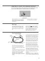
Typical Installation
Air inlet connector
NOTICE: The Canadian
Standards Association
mandates a manual gas
shut off valve: See CSA
B149.1- Installation
Code for complete
instructions. Local codes
or plumbing authority
requirements may vary
from the instructions or
diagrams provided and
take precedent over these
instructions.
Heat trap
6” (15.2 cm)
minimum
recommended
Air inlet
Union
(Recommended)
1/8” per foot minimum
slope upward for horizontal
venting.
Vent
Blower assembly
Hot water outlet to
fixtures
Union
(Recommended)
Vacuum Relief Valve
*10"
(25.4 cm)
min.
Heat trap
6” (15.2 cm)
minimum
recommended
* Typical for
both sides
Temperature and pressure
(T&P) relief valve
Shut-off
valve
Water Heater Jacket
To cold
water
Shut-off supply
valve
Thermal expansion
tank (if required)
Manual gas shut-off
To gas supply
Union
Relief valve discharge
line to suitable open
drain.
Condensate line
to suitable drain
On/Off
switch
Sediment
trap
Cap
Drain
valve
Condensate Trap
Gas Control (Thermostat)
Flammable Vapour Sensor
Auxiliary catch pan
Drain Pan Pipe
to suitable drain.
6” (15.2 cm)
Air gap
9
Installing the water heater
A new combination temperature and pressure relief valve, complying with the Standard for Relief Valves
and Automatic Gas Shut-Off Devices for Hot Water Supply Systems, ANSI Z21.22/CSA 4.4, is supplied
and must remain in the opening provided and marked for the purpose on the water heater. No valve of any
type should be installed between the relief valve and the tank.
Relief Valve
The pressure rating of the relief valve
must not exceed 150 PSI (1034 kPa), the
maximum working pressure of the water
heater as marked on the rating plate.
The Btuh rating of the relief valve must
equal or exceed the Btuh input of the
water heater as marked on its rating plate.
Position the outlet of the relief valve
above a suitable open drain to eliminate
potential water damage. Piping used
should be of a type approved for hot water
WARNING: The tank
must be full of water before
heater is turned on. The
water heater warranty does
not cover damage or failure
resulting from operation
with an empty or partially
empty tank.
distribution.
The discharge line must be no smaller
than the outlet of the valve and must
pitch downward from the valve to allow
complete drainage (by gravity) of the
relief valve and discharge line.
The end of the discharge line should not
be threaded or concealed and should be
protected from freezing. No valve of
any type, restriction, or reducer coupling
should be installed in the discharge line.
To Fill the Water Heater
Make certain that the drain valve is
closed, then open the shut-off valve in the
cold water supply line.
Open each hot water faucet slowly to
allow the air to vent from the water
heater and piping.
A steady flow of water from the hot water
faucet(s) indicates a full water heater.
Do not allow the flammable vapour sensor
to become submerged in water.
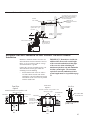
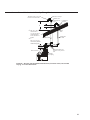
Condensate Management
Condensate Trap
Condensate Riser
(1/2" PVC pipe
supplied)
1/2" PVC tee (supplied)
Be sure the condensate runs freely to
the drain and does not accumulate in the
condensate trap or the condensate line. In
cold climates, precautions may need to be
taken to ensure that the condensate drain
lines do not freeze. A water proof heat
tape may be used to prevent freezing of
condensate lines.
Downward Slope
Drain Line
6" (15.2 cm)
air gap
Condensate Drain
NOTICE: If water
appears on the floor DO
NOT assume the tank in
leaking, check venting
and condensate line
connections.
NOTICE: Water Heater
should be leveled for
proper condensate
drainage.
10
This water heater generates condensate
and requires a drain to be located in close
proximity to allow condensate to drain
safely. The drain line and fittings should be
installed per installation instructions.
It is recommended that the condensate trap
be primed by filling the trap with 1/4 cup
of tap water before connecting the drain
lines.
• Condensate is mildly acidic and should
be collected and disposed per local codes.
• Use only PVC, CPVC pipe or flexible
tubing suitable for use with flue condensate
as drain line. If flexible tubing is used
ensure that there are no bends or twists and
has gradual slope to condensate drain.
• The drain line (along its entire length)
must be at least the same diameter as the
drain of the condensate trap (1/2”).
• The drain line must be short as possible
and have a downward slope towards the
condensate drain. If suitable slope is not
provided, the drain line can get blocked
and will cause improper operation of the
water heater. If a downward slope cannot
be provided, a condensate pump should
be used to pump condensate to a suitable
drain.
• The end of the drain line should be open
to the atmosphere. The end should not be
under water.
• Do not connect the drain line directly to
the sewer drain.
• Do not connect the drain line with drains
from other appliances.
• Do not drain condensate into the water
heater drain pan.
• Do not drain condensate over public way,
walkway or other areas where it will create
slippery condition, which could lead to
personal injury.
WARNING: Do not attempt to convert this water heater for use with a different type of gas other than the type
shown on the rating plate. Such conversion could result in hazardous operating conditions.
Gas Supply
The branch gas supply line to the water
heater should be a clean 1/2” black
steel pipe or other approved gas piping
material.
A union or ANSI design certified semirigid or flexible gas appliance connector
should be installed in the gas line close to
the water heater. The Canadian Standards
Association mandates a manual gas shut
off valve: See CSA B149.1- Installation
Code for complete instructions.
If flexible connectors are used, the
maximum length shall not exceed 36”
and must meet the requirements in ANSI
Z21.24-Connectors for Gas Appliances.
If lever type gas shut-offs are used,
they shall be T-Handle type.
Compound used on the threaded joints of
the gas piping must be of the type resistant
to the action of LP gas. Use compound
sparingly on male threads only.
Do not use excessive force (over 31.5 ft
lbs. (42.70 Nm)) in tightening the pipe
joint at the gas control (thermostat) inlet,
particularly if teflon pipe compound is
used, as the valve
body may be damaged.
The minimum inlet gas pressure (with
main burner on) to the water heater must
be a minimum of 5” w.c. (1.2 kPa) for
natural gas, and a minimum of
11” (2.7 kPa) w.c. for LP gas. The
maximum inlet pressure to the water
heater must not exceed 14" w.c. (3.5 kPa)
for natural gas and LP gas. For purposes
of input adjustment, the minimum inlet
gas pressure (with main burner on) is
shown on the water heater rating plate.
If high or low gas pressures are present,
contact your gas supplier for correction.
Where a sediment trap is not incorporated
as part of the appliance, a sediment
trap shall be installed downstream of
the equipment shutoff valve as close to
the inlet of the appliance as practical at
the time the appliance installation. The
sediment trap shall be either a tee fitting
with a capped nipple in the bottom outlet
or other device recognized as an effective
sediment trap.
WARNING: Never use
an open flame to test for
gas leaks, as property
damage, personal injury, or
death could result.
Leak Testing
The water heater and its gas connections
must be leak tested at normal operating
pressures before it is placed in operation.
urn on the manual gas shut-off
T
valve near the water heater.
se a soapy water solution to test for
U
leaks at all connections and fittings.
Bubbles indicate a gas leak that must
be corrected.
The factory connections to the gas
control (thermostat) should also be leak
tested after the water heater is placed in
operation.
Pressure Testing the Gas Supply System
The water heater and its manual gas
shut-off valve must be disconnected from
the gas supply piping system during any
pressure testing of that system at
pressures in excess of 1/2 psi (14” w.c.
(3.5 kPa)).
The water heater must be isolated from
the gas piping system by closing the
manual gas shut-off valve during any
pressure testing of the gas supply piping
at pressures equal to or less than
1/2 psi (14” w.c. (3.5 kPa)).
11
Installing the water heater
WARNING: Failure to
install a water heater
suitable for the altitude at
the location it is intended to
serve, can result in improper
operation of the appliance
resulting in property
damage and/or producing
carbon monoxide gas, which
could result in personal
injury, or death.
High Altitude
Input rating of this water heater is
based on sea level operation. At higher
elevations the actual input rate may be
lower than the value listed on the rating
label due to the derating of natural gas
and LP gas. This water heater can be
installed at elevations up to the elevation
listed on the rating plate attached to
the water heater without any change or
modifications.
Refer to the Venting Information tables on
page 13 for maximum vent lengths.
Contact the local gas supplier for more
information.
Vent and Combustion Air Inlet
DANGER: To avoid the
risk of fire, explosion, or
asphyxiation from carbon
monoxide, NEVER operate
the water heater unless it
is properly vented and the
Vent and Combustion Air
Inlet systems are properly
installed as detailed in the
"Vent and Combustion
Air Inlet" section of this
manual.
!
The vent pipe must overlap
a minimum of ½” on each
connection. It is important
that the vent pipe engages
fully into any pipe fitting
and be kept in that position
until the adhesive has fully
cured. DO NOT drill or
punch holes in the vent or
combustion air inlet pipe or
fittings.
NOTICE: This unit is
equipped with a Flammable
Vapour Sensor. Do not
apply power until enough
time has passed to allow the
vapours from the primer
and cement to dissipate.
This water heater is a direct vent appliance and
must be installed so that all air for combustion
is derived directly from the outside atmosphere
and all flue gases are discharged to the outside
atmosphere. For proper installation of the vent
and combustion air-inlet systems, follow the
instructions as detailed in this manual and
those per the current edition of CAN/CSA
B149.1 Natural Gas and Propane Installation
Code.
Vent and combustion air inlet pipe runs must
be adequately supported along both vertical
and horizontal lengths.
DO NOT connect this water heater to an
existing vent or chimney - it must be vented
separately from all other appliances.
The support method used should isolate the
vent and combustion air inlet pipes from floor
joists or other structural members to help
prevent the transmission of noise and vibration.
This water heater must be vented to the
outdoors with 2" or 3" diameter PVC or
CPVC pipe and fittings that is certified to
the current edition of ULC-S636.
The vent system must be installed in
accordance with the vent system manufacturer's
installation instructions.
The first 3 ft. (90 cm) of the vent pipe from
the appliance vent connector fitting must be
readily accessible for visible inspection.
NOTICE: This water heater is approved to
use the following materials for combustion
air-inlet pipe material:
PVC (Schedule 40, Cellular Core,
ASTM-F891)
PVC (DWV, ASTM-D2665)
PVC (Schedule 40, ASTM-D1785)
PVC (SDR Series, ASTM-D2241)
CPVC (CPVC 4120, ASTM-D2846)
CPVC (Schedule 40, ASTM-F441)
CPVC (SDR Series, ASTM-F442)
ABS (Schedule 40, DWV, ASTM-D2661)
ABS (Schedule 40, DWV, Cellular Core,
ASTM-F628)
NotICe: It is acceptable to interchange
PVC and CPVC pipe and fittings.
The unit may be vented horizontally through a
wall or vertically through the roof.
12
Maximum unsupported length is recommended
to be no more than 4 feet.
It is imperative that the first hanger be located
on the horizontal length immediately adjacent
to the first 90-degree elbow from the vertical
rise of vent pipe connected to the water heater.
Do not support, pin or otherwise secure the
vent and combustion air inlet systems in a way
that restricts the normal thermal expansion and
contraction of the chosen vent material and air
inlet pipe.
If the water heater is being installed as a
replacement for an existing power vented water
heater, a thorough inspection of the existing
vent and combustion air inlet system must be
performed prior to any installation work.
Verify that the correct materials as
detailed above have been used, and
that the minimum or maximum vent
and combustion air inlet length and
terminal locations as detailed in this
manual have been met.
Carefully inspect the entire vent and
combustion air inlet systems pipes for
any signs of cracks or fractures,
particularly at the joints between
elbows or other fittings and the
straight length of vent pipe.
Check the vent and combustion air
inlet systems for signs of sagging or
other stresses in the joints as a result
of misalignment of any components
in the systems.
If any of these conditions are found,
they must be corrected in accordance
with the instructions in this manual
before completing the installation and
putting the water heater into service.
The Minimum and Maximum equivalent lengths for the vent and combustion
air-inlet systems are shown in Table 1.
*Use only the 3 inch ULC-S636 concentric kit, Rheem part number (SP20261). The use of any other kit is not
approved. Contact your installer or local distributor for assistance. Refer to page 37 & 38 for installation of
alternate concentric vent termination.
Table 1
From 0 ft. through 4,500 ft. (1371 m)
Model
38 and 48
Gallon Heaters
Vent & Combustion
Air-Inlet System
Diameter
Min. Allowed Equivalent
Vent & Combustion AirInlet Lengths (Each Pipe
Run)
Max. Allowed Equivalent
Vent & Combustion AirInlet Lengths (Each Pipe
Run)
Inches
Feet
Feet
2
7 (2 m)
30 (9 m)
90° Elbows
Concentric*
3
7 (2 m)
60 (18 m)
90° Elbows
Concentric*
Vent and Combustion Air-Inlet
System Termination(s)
NOTICE: A 90° elbow is equivalent to 5 ft. of straight pipe. A 45° elbow is equivalent to 2.5 ft. of straight pipe.
The use of a 45° elbow is preferred over a 90° elbow. The vent and combustion air-inlet terminations are not
included in the equivalency calculations.
NOTICE: The mixing of 2" and 3" piping is not
allowed. If 3" pipe is used, a 3" to 2" reducer
fitting is allowed at the vent connector fitting.
This water heater is supplied with a 2" PVC
(Schedule 40) 90° vent terminal. When venting
with 3" pipe, Schedule 40 PVC 90° vent terminals
must be used. Screens for both 2" and 3" vent
terminals have been included.
3 in. diameter pipe
2 in. pipe diameter
3 in. diameter pipe
Vent
Combustion air-inlet
Min. 2 1/2 in. (6.3 cm)
to 6 in. (15.2 cm) Max.
Spacing
Min. 2 1/2 in. (6.3 cm)
to 6 in. (15.2 cm) Max.
Spacing
Vent Connector Fitting
Rubber Coupling
2 in. pipe diameter
Wind vane for 3" combustion inlet terminals have
been included. Wind vane should be cemented to
the combustion intake terminal using PVC cement.
Wind vane should be cemented as shown in figure
on page 16.
IMPORTANT: Ensure that all the coupling
clamps are tightened before allowing the water heater
to operate.
When using pipe and fittings, use 90° elbows of the
corresponding size and material for the vent terminal and
combustion air-inlet terminals.
Additional Fitting Considerations
DO NOT use short sweep
elbows. It is recommended to use
only standard and/or long sweep
elbows. See examples as shown.
DO NOT use.
Short Sweep 90° Elbow
•Maintain a minimum vertical height of 6 in. (15.2 cm)
of pipe, including pipe increasers (if used), from the
blower exhaust coupling before a transition into any
elbow.
Elbows are limited to a total equivalent length of 20 ft.
(6 m). Maximum allowed four (4) 90° elbows or eight
(8) 45° elbows.
Examples of Elbows:
GOOD
Standard 90° Elbow
BEST
Long Sweep 90° Elbow
13
Installing the Water Heater
Direct Vent Terminal Location
G
v
H
A
D
E
V
B
B
B
C
V
L
LE
RAB
OPE
F
I
v
B
A
M
X
K
X
v
B
v
v
ED
FIX ED
S
CLO
v
ED
FIX ED
S
CLO
v
ABLE
OPER
J
B
The following information should be used for determining the proper location of the vent terminal for the water heater.
V Vent Terminal
X
Air Supply Inlet
Area Where Terminal Is Not Permitted
Canadian Installations1
A = Clearance above grade, veranda, porch, deck 1ft. (30 cm)
or balcony
B = C
learance to window or door that may be
1 ft. (30 cm) for appliances> 10,000 Btuh (3 kW)
opened
C = C
learance to permanently closed window
1 ft. (30 cm)
D = Vertical clearance to ventilated soffit located 2 ft. (61 cm)
above the terminal
E - C
learance to unventilated soffit
1 ft. (30 cm)
F - Clearance to outside corner
1 ft. (30 cm)
G - C
learance to inside corner
2 ft. (61 cm)
H - Clearance to each side of center line extended 3 ft. (91 cm) within a height 15 ft. (4.5 m) above the meter/
above meter/regulator assembly
regulator assembly
I - Clearance to service regulator vent outlet
3 ft. (91 cm)
J - Clearance to non mechanical air supply inlet
1 ft. (30 cm) for appliances> 10,000 Btuh (3 kW)
to building or the combustion air inlet to any
other appliance
K - C
learance to a mechanical air supply inlet
6 ft. (1.83 m)
L - Clearance above paved sidewalk or paved
7 ft. (2.13 m )*
driveway located on public property
M - Clearance under veranda, porch, deck, or
1ft. (30 cm )**
balcony
In accordance with the CSA B149.1, Natural Gas and Propane Installation Code
* A vent shall not be terminated directly above a paved sidewalk or paved driveway that is located on public property.
**Permitted only if veranda, porch, deck, or balcony is fully open on a minimum of two sides beneath the floor; and the distance between the top of the vent termination and the underside of the veranda, porch or deck is greater than 1ft. (30 cm).
++ A vent shall not terminate where it may cause hazardous frost or ice accumulations on adjacent property surfaces.
For clearances not specified in CSA B149.1, the following statement shall be included: "Clearance in accordance with local installation codes and the requirements of the gas supplier and the manufacturer's installation instructions."
1
14
Terminal Location Additional
Considerations
Caulk
To help prevent moisture from freezing on walls and under
eaves, do not locate the vent terminal on the side of a
building with prevailing winter winds.
Rising moisture will
collect under eves
If soffit vent is too close,
block off and install new vent
at another location
6 ft.
(1.8 m)
hen terminating the vent and combustion air-inlet pipes
W
through brick or masonry surfaces, the installation of a rust
resistant sheet metal backing plates behind the vent and
combustion air-inlet terminals are recommended.
Inside
Corner
Chalk
12 in. min.
above grade or above
anticipated snow level.
4 ft.'
(1.22 m)
Recommended
Vent
Wind
Vane
6 ft. (1.8) Caulk zone
or to edge of window etc.,
starting within 6 ft. (1.8 m)
DO Not locate the vent terminal too close to shrubbery, as
flue gasses may damage them.
aulk all cracks, seams and joints within 6 ft. (1.8 m) of the
C
vent and combustion air-inlet terminals.
Combustion
Air-Inlet
I n cold climates, precautions may need to be taken to ensure
that the condensate in the vent pipe does not freeze.
WARNING : Moisture in the flue gas will condense as it
leaves the vent terminal. In cold weather this condensate can
freeze on the exterior wall, under the eaves and on
surrounding objects. Some discoloration to the exterior of
the building is to be expected. However, improper location or
installation can result in severe damage to the structure or
exterior finish of the building
upport horizontal sections of the vent and combustion
S
air-inlet pipe every 4 ft. (1.2 m) DO NOT rigidly secure
the vent system. Provisions must be made to allow for
expansion and contraction of the vent system.
O NOT install the vent and combustion air-inlet terminals
D
less than 1 ft. (30.5 cm) above grade or average snowfall
whichever is greater.
ermanently seal annular openings around the vent and
P
combustion air-inlet system penetrations using approved
materials to prevent entry of combustion products into the
building.
Notice: The vent and Horizontal Vent and Combustion Air-Inlet Terminal
combustion air-inlet
Installation
systems of this water
Determine the locations for the vent and
When installing 3" (7.6 cm) vent terminals
heater may be installed
horizontally through
combustion air-inlet terminals per information
install the supplied 1/2 in. mesh metal screens
a wall or vertically
on previous page and section above then make
inside each terminal fitting.
through the roof.
two (2) holes through the exterior wall to
Connect the terminals to the vent and
accommodate the vent and combustion air-inlet combustion air-inlet pipes which are extending
The vent and
pipes.
combustion air-inlet
out of the building.
terminals of the water
• Maintain a minimum horizontal distance
• Ensure that the back of the supplied
heater must be installed
of 12 in. (30.5 cm) between the vent and
terminals are flush with the outside wall
in the same atmospheric
combustion air- inlet terminal center lines.
pressure zone with a
surface.
minimum horizontal
Insert lengths of vent and combustion air-inlet
Complete the installation of the remainder
distance of 12 inches and pipes through the wall as shown.
of the vent system and attach it to the vent
a maximum horizontal
• Allow sufficient length of pipe to extend
connector fitting on the water heater’s blower
distance of 30 inches
beyond the exterior wall of the building for
assembly.
between the vent and
attachment of the vent and combustion aircombustion air- inlet
• Horizontal lengths of the vent system must
terminal center lines.
inlet terminals.
slope upward a minimum of 1/8 in. per foot
• M
aintain a minimum distance from the vent
and combustion air-inlet terminals of not less
than 1 ft. (30.5 cm) above grade or average
snowfall whichever is greater.
12 in. (30.5 cm)
Min.
Exhaust Vent
Terminal
Combustion AirInlet Terminal
as shown in figure on next page.
Wind
Vane
15
Installing the water heater
Horizontal Vent and Combustion Air-Inlet Terminal Installation
continued Complete the installation of the remainder of the
combustion air-inlet system and attach it to the
combustion air-inlet connector fitting on the water
heater’s combustion air-inlet tube assembly.
Support vertical and horizontal lengths of the vent
and combustion air-inlet systems as previously
mentioned.
2 ft. (60.9 cm) x 2 ft. (60.9 cm)
Sheet Metal Shield on Brick or
Masonry Walls (Optional for air
inlet termination)
Combustion
Air-Inlet
Terminals with 1/2 in.
Mesh Protective Screens
Inside
Exhaust Vent
Vent Pipe
termination
Slope horizontal pipe
upward 1/8 in. per foot min.
Min 6 in.
(15.2 cm)
Wind Vane on
Combustion
Air-Inlet
Termination
Combustion
Air-Inlet
Rear of Termination
Flush with Outside
of Wall
Vent Connector Fitting
d
.008
-Bd
.010
Top Pan
Inside of
Building
Outside of
Building
Horizontal Vent and Combustion Air-Inlet Terminal Installation
90° Elbow
Wind Vane
The illustration on the left is a enlarged
view of the elbow, "Wind Vane", and
screen assembly on the Combustion AirInlet Termination.
Screen
16
Alternate Horizontal Vent and Combustion Air-Inlet Terminal Installation
2 ft. (60.9 cm) x 2 ft. (60.9 cm)
Sheet Metal Shield on Brick or
Masonry Walls (Optional for
air inlet termination)
Exhaust
Vent
Slope horizontal pipe
upward 1/8 in. per
foot min.
Slope horizontal
pipe upward 1/8
in. per foot min.
Inside of
Building
Min 6 in.
(15.2 cm)
Wind Vane on
Combustion Air-Inlet
Terminal
Rear of Termination
Flush with Outside
of Wall
Outside of
Building
Combustion Air-Inlet
Vent Connector Fitting
Slope horizontal
pipe upward 1/8
in. per foot min.
d
.008
-Bd
.010
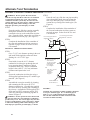
Horizontal Vent and Combustion Air-Inlet Alternate Vent Riser Terminal
Installation
Maintain a minimum distance from the vent
and combustion air-inlet terminals of not less
than 1 ft. (30.5 cm) above grade or average
snowfall whichever is greater.
Connect the vent riser assemblies to the vent
and combustion air-inlet pipes which are
extending out of the building.
•
Ensure that the back of the 90° elbows
are flush with the outside wall surface
and that the vent and combustion air-inlet
terminations of the vent risers are parallel
with the outside wall.
Front View
Option 2
Front View
Option 1
Short piece of pipe
Short piece of pipe
Combustion Air
Inlet
12 in.
(30.5 cm)
Min.
and
30 in.
(76 cm)
Max.
Wind Vane
Side View
Terminal assemblies to be parallel to wall
Terminal assemblies to be parallel to wall.
Vent Outlet
IMPORTANT: Remember to include the
additional 90° elbows and vertical height
of the vent and combustion air-inlet pipes
of the vent riser when calculating the
maximum equivalent vent and combustion
air-inlet system lengths. The maximum
equivalent vent and combustion air-inlet
system lengths must be as specified on page
13.
Vent Outlet
*
Combustion Air
Inlet
Rear of elbow flush
with outside wall
Wind Vane
Termination
Openings 12 in.
(30.5 cm) min. above
grade or anticipated
snow level
*
* Clearance is equal and
parallel to wall
12 in.
(30.5 cm)
Min.
and
30 in.
(76 cm)
Max.
17
Installing the Water Heater
Vertical Vent and Combustion Air-Inlet Installation
The location of the vent and combustion air-inlet
terminals depends on the following minimum clearances
and considerations.
Exhaust Vent and Combustion Air-Inlet
Pipe Through Roof
Minimum 18 in. (46 cm) above roof.
inimum 12 in. (30.5 cm) above anticipated snow
M
level.
Terminals with 1/2 in. mesh
Protective Screens and
Termination Restrictors Inside.
aximum 24 in. (61 cm) above roof level without
M
additional support for vent.
Short Piece of Pipe
our (4) ft. (1.2 m) from any gable, dormer or other
F
roof structure with building interior access (i.e., vent,
window, etc.).
Exhaust Vent
Elbow
ithin (6) ft. (1.8 m) of any mechanical air supply
W
inlet.
Short Piece of Pipe
aintain a minimum horizontal distance of
M
12 in. (30.5 cm) between the vent and combustion
air-inlet terminal center lines.
Determine the locations for the vent and combustion
air-inlet terminals then make two (2) holes through the
roof and interior ceiling(s) to accommodate the vent and
combustion air-inlet pipes.
Assemble the vent pipe assembly.
Install the vent system and attach it to the vent connector
fitting on the water heater’s blower assembly.
Horizontal lengths of the vent system must slope upwards
a minimum of 1/8 in. per foot.
Install the combustion air-inlet system and attach it to the
combustion air-inlet rubber coupling on the water heater’s
combustion air-inlet tube assembly.
#
Combustion
Air-Inlet
#
Wind
Vane
# M
in. 18 in. (46 cm)
Above Roof or
12" (30.5 cm) above
Anticipated Snow
Level; whichever is highest
Exhaust Vent
and
Max. 24 in. (61 cm)
Above Roof
(Without Additional
Support)
Combustion
Air-Inlet
Vent Connector
Rubber
Coupling
Support vertical and horizontal lengths of the vent and
combustion air-inlet systems as previously mentioned.
Determine the vent and combustion air-inlet terminal
heights and cut the pipe accordingly. Insert lengths of vent
and combustion air-inlet pipes through the ceiling wall as
shown.
Install adequate flashing where the vent and combustion
air-inlet pipes pass through the roof.
Connect vent elbow onto vertical pipe through roof.
Connect a short piece of pipe approximately 3 in. between
the terminals and elbows.
18
d
.008
-B-
Alternate Vent and Combustion Air-Inlet Pipe Through Roof
Terminals with 1/2 in. mesh
Protective Screens Inside.
Short Piece of Pipe
Exhaust Vent
Short Piece of
Pipe
#
Combustion
Air-Inlet
#
# M
in. 18 in. (46 cm)
Wind
Vane
Above Roof or
12" (30.5 cm) above
Anticipated Snow
Level; whichever is
highest
Combustion
Air-Inlet
Exhaust Vent
and
Max. 24 in. (61 cm)
Above Roof (Without
Additional Support)
Min 6 in.
(15.2 cm)
Slope horizontal pipe
upward 1/8 in. per foot
min.
Vent Connector
d
.008
-B-
Rubber
Coupling
NOTICE: Alternate Vent Termination Instructions (Concentric Vent) can be found
on page 37 & 38 of this manual.
19
Installing the Water Heater
NOTICE: All pipe, fittings, solvent cement, primers and procedures must conform to American National
Standards Institute and American Society for Testing and Materials (ANSI/ASTM) standards.
Cementing Joints
WARNING: DANGER
OF FIRE OR BODILY
INJURY - Solvent cements
and primers are highly
flammable. Provide
adequate ventilation and do
not assemble near heat
source or open flame. Do not
smoke. Avoid skin or eye
contact. Observe all cautions
and warnings on material
containers.
CAUTION:
For proper installation:
DO NOT use solvent cement
that has become curdled,
lumpy or thickened.
DO NOT thin solvent
cement. Observe shelf
precautions printed on the
containers.
For applications below
32°F (0°C) use only low
temperature type solvent
cement.
Appropriate solvent and
cleaner must be used for the
type of vent pipe used.
Combustion Air Inlet:
Vent:
All joints in the combustion air inlet
piping must be properly sealed and the
following materials are recommended:
NOTICE: All joints in the vent piping
must be properly sealed. Follow the
instructions provided by the vent
manufacturer for sealing the joints.
PVC materials should use ASTM D2564
grade cement.
CPVC materials should use ASTM F493
grade cement.
Cleaner-Primer and Medium Body Solvent
Cement:
ut pipe end square, remove jagged
C
edges and burrs. Chamfer end of pipe,
then clean fitting socket and pipe joint
area of all dirt, grease or moisture.
After checking pipe and socket for
proper fit, wipe socket and pipe with
cleaner-primer. Apply a liberal coat of
primer to inside surface of socket and
outside of pipe. Do not allow primer to
dry before applying cement.
Apply a thin coat of cement evenly in
the socket. Quickly apply a heavy coat
of cement to the pipe end and insert
pipe into fitting with a slight twisting
motion until it bottoms out.
NOTICE: Cement must be fluid; if not,
recoat.
Hold the pipe fitting for 30 seconds to
prevent the tapered socket from pushing
the pipe out of the fitting.
Wipe all excess cement from the joint
with a rag. Allow 15 minutes before
handling. Cure time will vary according
to fit, temperature and humidity.
NOTICE: Stir the solvent cement
frequently while using. Use a natural
bristle brush or the dauber supplied
with the can. The proper brush size is
one inch.
NOTICE: This unit is equipped with
a Flammable Vapour Sensor. Do not
apply power until enough time has
passed to allow the vapours from the
primer and cement to dissipate.
20
NOTICE: Vent pipe, fittings, solvent
cement, primer, and procedures
must conform to ULC-S636 vent
manufacturer's requirements.
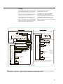
Wiring
If local codes permit, the water heater may
be connected to electric service with the
power cord provided (DO NOT use an
extension cord). A grounding receptacle is
required. Ensure polarity is correct.
The maximum current draw is
approximately 5.0 amps.
The water heater must be electrically
grounded in accordance with local
codes, or, in the absence of local codes,
in accordance with latest edition of the
Canadian Electrical Code CSA C22.1.
Refer to the figures below for water heater
internal wiring.
If local codes do not permit the use of
cord connections, a 120 V, 60 Hz power
supply, with suitable disconnecting means,
must be connected to the black and white
leads in the heater control enclosure.
H
CONNECTOR DIAGRAM
120 VAC
120 VAC PLUG FOR POWERVENT
BLOWER ASSEMBLY
H
BK
G
W
G
N
1 BL
TEMPERATURE
SWITCH NC
BLOWER
VAC
SW NO
5 Y
GAS VALVE
1 2
3 4 5
6
GAS VALVE
W BK R Y BL G
BL
N/C
R
Y
W
1 W
2 W
3 W
IGNITER AND
FLAME SENSOR
MOT
BLOWER
GND
1 W
IGNITER
2 W
3 W
FLAME SENSOR
1
2
COMM PORT
3
4
1 BK
2
3
1
2 COMM PORT
3
4
BK
FLAMMABLE
VAPOR SENSOR
1
AUX PORT *
2
BK
1
2
BK
3
INTELLI-VENT ELECTRONIC CONTROL
INTELLI-VENT ELECTRONIC CONTROL
WIRE HARNESS THAT RUNS FROM BLOWER
ASSEMBLY TO GAS VALVE CONTROL
FV
BK
BL
G
R
W
Y
=
=
=
=
=
=
BLACK
BLUE
GREEN
RED
WHITE
YELLOW
G
1
2 R
FLAMMABLE
VAPOR SENSOR
3
1
AUX PORT *
2
1 G
2 R
VAC
SW NC
6 W
W BK R Y BL G
GND
VAC
SW NO
3 BK
4 R
6 PIN CONNECTOR
BK
TEMPERATURE
SWITCH NC
2 N/C
VAC
SW NC
MOT
POWER
SCREW
VENT BLOWER
GND
ASSEMBLY
1
2
3
4
5
6
N
SCHEMATIC DIAGRAM
BK
THERMISTORS
4 R
3 BK
TS2
4 R
TS1
NOTE: IF ANY OF THE ORIGINAL WIRE SUPPLIED WITH THE APPLIANCE
MUST BE REPLACED, IT MUST BE REPLACED WITH A 18 GA, 600 V,
105º C WIRE.
THERMISTORS
G
H
N
120V / 60 Hz LESS THAN 5 AMPS
* NOT AVAILABLE ON ALL MODELS
AX5168
CAUTION! Label all wires prior to disconnection when servicing controls. Wiring errors can cause improper
and dangerous operation. VERIFY PROPER OPERATION AFTER SERVICING!
Rheem
9-1554
5.5” X 6.5”
{ENGLISH}
AX5168
Black
21
Installing the water heater
Insulation Blankets
WARNING: If local
codes require external
application of insulation
blanket kits the
manufacturer’s instructions
included with the kit must
be carefully followed.
Insulation blankets, available to the
general public, for external use on gas
water heaters are not necessary. The
purpose of an insulation blanket is to
reduce the standby heat loss encountered
with storage tank heaters. This water
heater meets or exceeds the National
Appliance Energy Conservation Act
standards with respect to insulation and
standby loss requirements making an
insulation blanket unnecessary.
The manufacturer’s warranty does not
cover any damage or defect caused by
installation, attachment or use of
any type of energy saving or other
unapproved devices (other than those
authorized by the manufacturer) into, onto
or in conjunction with the water heater.
The use of unauthorized energy saving
devices may shorten the life of the water
heater and may endanger life and property.
The manufacturer disclaims any
responsibility for such loss or injury
resulting from the use of such
unauthorized devices.
CAUTION: If local codes require the
application of an external insulation
blanket to this water heater, pay careful
attention to the following so as not to
restrict the proper function and
operation of the water heater:
● Do not cover the operating or
warning labels attached to the water
heater or attempt to relocate them on
the exterior of insulation blanket.
● Do not apply insulation to the top
of the water heater. This will interfere
with the safe operation of the blower
assembly.
Do not cover the burner access door,
jacket door, condensate trap, gas control
(thermostat) or pressure and temperature
relief valve.
Do not apply insulation to the
bottom of the water heater or the area
where the Flammable Vapour Sensor is
located. This area must be unobstructed
so as not to restrict operation of the
sensor.
Inspect the insulation blanket frequently
making certain it has not sagged down
onto the Flammable Vapour sensor
located around the lower perimeter of
the water heater jacket. This could result
in an unsafe operating condition.
Hot and Cold Pipe Insulation Installation
22
Typical vertical piping arrangement
Typical horizontal piping arrangement
For increased energy efficiency, some
water heaters have been supplied with two
24” (61 cm) sections of pipe insulation.
Install the insulation, according to the
illustrations above, that best meets your
requirements.
Temperature & Pressure (T&P) Insulation Installation
For increased energy efficiency, this water heater has been supplied with a 2-3/8”
(6 cm) section of T&P insulation. Install the insulation as shown below.
Typical Side Connect T & P
Arrangement.
Slip the insulation cover over the T&P
Valve through the center hole and align
the hole in the side with the opening of
the T&P Valve.
Heat Trap
For increased energy efficiency, some
water heaters have been supplied with
factory installed 3/4” NPT heat traps in
the hot outlet line and cold water inlet
line.
Ensure the T&P Valve opening is
not obstructed by the insulation.
These heat traps may require a minimum
of one (1) 90° 3/4” NPT elbow and may
require an additional 90° 3/4” NPT elbow
or a 3/4” coupling depending on your
installation needs. See Illustration of
nipples and heat traps on page 36.
Top Cap Installation
2 screws
(mounting
tabs)
Top Cap View
Outside
Inside
3 Dual Lock®
Strips
Inside Center
Front
Read these instructions thoroughly and
make sure you understand all the steps
and procedures before proceeding with the
installation.
Carefully remove the Top Cap from the water heater carton. Install the water heater as
specified per this Use & Care Manual.
Notice: Also see information as
detailed in “Water Supply Connections”
section.
Locate the small plastic bag containing the
three (3) Dual Lock® strips and two (2)
sheet metal screws to be used to attach the
Top Cap in the Use & Care Manual bag.
Peel off one side of the Dual Lock® strips
and firmly press near the Top Cap mounting tabs and the inside center front of the
rim on the Top Cap, see figure on left.
Peel off the other side of the Dual Lock®
strips and place the Top Cap on the top
front center of the water heater ensuring
that it is aligned correctly and properly
positioned on top of the water heater. Press
firmly to ensure proper attachment is made.
Align holes in mounting tabs on the Top
Cap with the holes in the top of the heater
then secure the Top Cap to the water heater
with the two (2) #8 sheet metal screws
(supplied).
IMPORTANT: Do not over tighten the
screws as this may damage the Top Cap.
23
Installing the water heater
During Installation of this water heater...........
DO
DO check inlet gas pressure to
ensure that it is within the range
specified on the rating plate.
DO maintain proper
clearances to combustibles as
specified on the rating plate.
DO allow enough time for
joint cement vapours to dissipate
BEFORE applying power to the
water heater.
DO ensure that the venting
system complies with the guidelines
found in the Use and Care Manual
and CAN/CSA B149.1.
DO contact a qualified service
technician if the main burner will
not stay lit. The burner chamber
is designed to be sealed utilizing a
gasket and tamper resistant screws.
DO provide proper slope for
condensate drain line.
Burner Access
Door Grommet
Flammable
Vapour
Sensor
24
Sight Glass
DON’T
DON’T block the Flammable
Vapour Sensor located around the
lower portion of the water heater
jacket.
DON’T remove the Burner
Access Door unless absolutely
necessary. This should only
be done by a qualified service
technician. A new burner access
door gasket must be installed on
any burner access door that has
been removed.
DON’T install this water
heater where standing water may
occur. The base of the water
heater is meant to be mounted on
a dry surface.
DON’T allow cleaners,
solvents, or other materials
to come into contact with the
Flammable Vapour Sensor.
DON’T operate the water
heater if the sight glass or burner
access door grommet is damaged
or broken (see illustration at left).
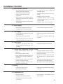
Installation Checklist
A. Water Heater Location
In a location where the vent and combustion
air-inlet systems will be within the
requirements specified in this manual.
Indoors and protected from freezing
temperatures.
Proper clearance from combustible surfaces
observed and water heater not installed on
carpeted floor.
Sufficient fresh air supply for proper operation
of water heater.
Air supply free of corrosive elements and
flammable vapours.
Provisions made to protect area from water
damage.
Sufficient room to service heater.
Combustible materials, such as clothing,
cleaning materials, rags, etc., clear of the
base of the heater.
Flammable vapour sensor is not blocked.
B. Water Supply
Water heater completely filled with water.
Air purged from water heater and piping.
Water connections tight and free of leaks.
C. Gas Supply
Gas line equipped with shut-off valve, union
Check inlet gas pressure (with main burner
Approved pipe joint compound used.
Soap and water solution used to check all
connections and fittings for possible gas leak.
and sediment trap.
on).
Gas Company inspected installation (if
required).
D. Relief Valve
Temperature and Pressure Relief Valve
Discharge line protected from freezing.
properly installed and discharge line run to
open drain.
E. Venting and combustion air-inlet systems
Heater vented separately from all other
appliances.
Blower assembly properly installed.
Appropriate minimum clearances observed.
Precautions taken to prevent moisture damage
around vent termination.
Proper materials and techniques used in the
installation of the vent and combustion airinlet systems.
Vapours from vent pipe cement and primer
Vent pipe properly secured to the exhaust
connector of the blower assembly.
Combustion air-inlet pipe properly secured to
Vent and combination air-inlet systems
supported at required intervals.
Horizontal section of vent sloped upward.
have dissipated prior to applying electrical
power.
the combustion air-inlet rubber coupling.
F. Wiring
Correct power supply (120 V).
Electrical connections tight.
Heater properly grounded and proper polarity
observed.
Check for leaks in the condensate trap and
line connections.
G. Condensate Line
Sloped toward drain.
Condensate drain line hoses clamped.
Condensate drain protected from freezing
(if necessary).
25
Supplemental instructions for gas water heaters installed
in potable water/space heating applications
Local codes or plumbing authority requirements may vary from the instructions or diagrams provided in this
manual and take precedent over these instructions.
Hot water
supply to
house
Hot water
supply to
heating
unit
From HOT
outlet on
water heater
Tee fitting for vertical hot
water supply lines.
From HOT
outlet on
water heater
Hot water
supply to
house
Hot water supply
to heating unit
Tee fitting for horizontal hot
water supply lines.
Combination Potable Water and Space Heating Application
Tee fitting must be installed as shown.
This ensures that any air in the water lines
will be purged through the domestic water
faucets and showers.
DANGER: When this system
requires water for space heating at
elevated temperatures (above 125°F)
(52°C), a mixing or tempering valve
must be installed in the hot water
supply line to the house in order to
reduce the scald hazard potential.
DANGER: Any piping or components
used in the installation of this water
heater in a combination potable and
space heating application must be
suitable for use with drinking water.
DANGER: If this water heater is
installed in an application intended to
supply domestic hot water needs and
hot water for space heating purposes,
do not connect the heater to an existing
heating unit or components of a heating
system that have previously been used
with a non drinking water system. Toxic
chemicals such as those used for boiler
treatment may be present and will
contaminate the drinking water supply
causing possible health risks. Never
introduce toxic chemicals, such as those
used for boiler treatment, into this
system.
NOTICE: Suitable for (potable) water
heating and space heating applications.
DO NOT use for space heating
application only.
Typical Piping Diagram for Combination Potable/Space Heating Installation
Nominal 3/4" size mixing or tempering valve
(refer to warning above). Follow mixing or
tempering valve manufacturer’s instructions for
installation of the valve.
Minimum of 2'-0" developed
length of 3/4" pipe.
Air vent
Pressure Gauge
3/4" Tempered
domestic hot water
supply to house.
3/4" cold water supply
3/4" Shut-Off Valve (Typ.)
Spring loaded check valve in heating unit
hot water supply line and cold water return
line (not supplied with water heater)
NOTE: This check valve is incorporated
in some heating units. Refer to the
installation instructions supplied with
specific heating unit to determine if it is
required.
3/4" Shut-Off Valve
(Typ.)
Heat Trap
6” Min.
2 Gallon (7.6 ltr)
Thermal Expansion
Tank (if required-not
supplied with water
heater)
3/4" ShutOff Valve
(Typ.)
Isolation valve in hot water supply line
to heating unit (not supplied with water
heater)
See diagrams above for proper
pipe application for vertical
or horizontal supply lines.
Hot water
to space heater
Hot water coil
All bronze pump.
°F
140
3/4" HWS & HWR
to Heating Coil.
Drain valve
(not supplied with
water heater)
Gas line to water heater
Gas Fired
Water Heater
Isolation valve in
cold water return line
from heating unit (not
supplied with water
heater)
Check valve
internal in pump.
F
30°
1
F to
°
120
Temperature and Pressure Relief
Valve, tie to location approved by
local code
Temperature and pressure relief
valve discharge line
3/4" Check Valve with 1/8" Hole
Air bleed valve.
Water Sample Tap.
Air Handler
To HVAC Unit.
T FAN
ON
OFF
HEAT
COOL
Electronically controlled pump
timer. Activates every 6 hours
for 60 seconds. Wire to bronze
pump.
Gas Control (Thermostat)
Water Heater drain pan installed
in accordance with the Local and
Provincial Code
6” (15.2 cm)
Air Gap
26
Lighting the water heater
Before operating this water heater, be sure to read and follow the instructions on the label pictured below and
all other labels on the water heater, as well as the warnings printed in this manual. Failure to do so can result
in unsafe operation of the water heater resulting in property damage, personal injury, or death. Should you
have any problems reading or following the instructions in this manual, STOP, and get help from a qualified
person.
FOR YOUR SAFETY READ BEFORE OPERATING
WARNING: If you do not follow these instructions and the Use & Care
Manual instructions exactly, a fire or explosion may result causing property
damage, personal injury or loss of life.
A. This appliance does not have a pilot. It is
equipped with an ignition device which automatically lights the burner. Do NOT try to light
the burner by hand.
B. BEFORE PUTTING THIS APPLIANCE INTO
SERVICE - Smell all around the appliance
area for gas. Be sure to smell next to the
floor because some gas is heavier than air
and will settle on the floor.
WHAT TO DO IF YOU SMELL GAS
Do not try to light any appliance.
Do not touch any electric switch; do
not use any phone in your building.
Immediately call your gas supplier
from a neighbor’s phone. Follow the
gas supplier’s instructions.
If you cannot reach your gas
supplier, call the fire department.
C. Use only your hand to push in the gas
control buttons. Never use tools. If the
control buttons will not push in, don’t try
to repair them, call a qualified service
technician. Force or attempted repair
may result in fire or explosion.
D. Do not use this appliance if any part has
been under water. Immediately call a
qualified installer or service agency to
replace a flooded water heater. Do not
attempt to repair the unit! It must be
replaced!
OPERATING INSTRUCTIONS
1. Stop! Read the safety information above
8. Turn on all electrical power to the appliance.
on this label.
Toggle the “ON/OFF” switch located on the
2. Toggle the “ON/OFF” switch located on the 9. gas control to the “ON” position.
gas control to the “ON” position.
3. Set the thermostat to the lowest setting 10. Set thermostat to the desired temperature
setting by pressing the COOLER and
by pressing the COOLER and HOTTER
HOTTER buttons at the same time and
buttons
at
the
same
time
and
holding
holding them for (1) second. Depress the
them for (1) second. Depress the COOLER
HOTTER button until the desired
button until only the VAC indicator
temperature display setting is lit. The
light is lit.
preferred starting point for temperature
4. Toggle the “ON/OFF” switch located on the
setting is indicated by on the thermostat.
gas control to the “OFF” position.
5. Turn off all electrical power to the appliance. 11. If the appliance will not operate, follow
the instructions “TO TURN OFF GAS TO
6. This appliance is equipped with a Hot
APPLIANCE” and call your service
Surface Ignition System which autotechnician or gas supplier.
matically lights the burner. Do NOT open
the inner door of this appliance and try to
light the burner by hand!
ON/OFF
SWITCH
COOLER/HOTTER
7. Wait five (5) minutes to clear out any gas.
BUTTONS
If you smell gas, STOP! Follow “B” in the
safety information above on this label. If
you do not smell gas, go ahead to the next step.
VAC
A
B
COOLER
C
HOTTER
SCALDING RISK INCREASES
WITH HOTTER WATER
TO TURN GAS OFF TO THE APPLIANCE
and HOTTER
button
buttons at the same time and holding for (1) second. Depress the COOLER
until only the VAC indicator light is lit.
1. Set the thermostat to the lowest setting by first depressing the COOLER
2. Toggle the “ON/OFF” switch located on the gas control to the “OFF” position.
3. Turn off all electrical power to the appliance.
27
Operating the water heater
CAUTION: Hydrogen gas can be produced in a hot water system served by this water heater that has not been
used for a long period of time (generally two weeks or more). HYDROGEN GAS IS EXTREMELY
FLAMMABLE!! To dissipate such gas and to reduce risk of injury, it is recommended that the hot water faucet be
opened for several minutes at the kitchen sink before using any electrical appliance connected to the hot water
system. If hydrogen is present, there will be an unusual sound such as air escaping through the pipe as the water
begins to flow. Do not smoke or use an open flame near the faucet at the time it is open.
Safety Precautions
o turn off manual gas shut-off valve
D
if water heater has been subjected to
over heating, fire, flood, physical
damage or if the gas supply fails
to shut off.
o Not turn on water heater unless it
D
is completely filled with water.
o Not turn on water heater if cold
D
water supply shut-off valve is closed.
o Not allow combustible materials
D
such as newspaper, rags or mops to
accumulate near water heater.
o Not store or use gasoline or other
D
flammable vapours and liquids, such
as adhesives or paint thinner, in
vicinity of this or any other appliance.
If such flammables must be used, open
doors and windows for ventilation, and
all gas burning appliances in the
vicinity should be shut off including
their pilot burners, to avoid vapours
lighting.
NOTICE: Flammable vapours can be
drawn by air currents from surrounding
areas to the water heater.
I f there is any difficulty in
understanding or following the
Operating Instructions or the Care and
Cleaning section, it is recommended
that a qualified person or serviceman
perform the work.
Operating Procedure
This heater is equipped with a hot surface
ignitor to light the main burner. There is
no pilot light to be lit, but on initial startup, it is recommended that the outer door
be removed (leave inner door in place for
safety) to determine if the hot surface ignitor
and main burner are operating properly.
Once filled with water, it is only necessary
to plug the power cord in and make sure
the “ON/OFF” switch located on the gas
control (thermostat) is in the “ON” position
to put the water heater into operation. Within
seconds the hot surface ignitor should heat
up, then the gas control (thermostat) should
open and the main burner ignite. After the
main burner ignites, replace the outer door.
If no main burner flame is established, the
gas control (thermostat) will go through three
trials for ignition before going into a lockout. A warning light will alert the user of this
lock-out condition. If this happens, refer to
“Troubleshooting Guide.”
TO SHUT OFF WATER HEATER – Turn
switch on the gas control (thermostat) to the
“OFF” position.
Water Temperature Setting
! DANGER: Hotter water
increases the Potential
for Hot Water SCALDS.
Households with small
children, disabled, or elderly
persons may require a 120°F
(49°C) or lower gas control
(thermostat) setting to
prevent contact with HOT
water.
The temperature of the water in the water
heater can be regulated by pressing the
buttons on the front of the gas control
(thermostat).
Safety and energy conservation are factors
to be considered when selecting the water
temperature setting of the water heater’s
gas control (thermostat(s)). The lower the
temperature setting, the greater the savings
in energy and operating costs.
To comply with safety regulations, the gas
control (thermostat) was set at its lowest
setting before the water heater was shipped
from the factory. The recommended
starting point temperature is 120°F (49°C).
28
Water temperatures above 125°F (52°C)
can cause severe burns or death from
scalding. Be sure to read and follow the
warnings outlined in this manual and on
the label located on the water heater near
the gas control (thermostat).
Mixing valves are available for reducing
point of use water temperature by mixing
hot and cold water in branch water
lines. Contact a licensed plumber or
the local plumbing authority for further
information. (See page 4 for more details.)
The chart on the next page may be used
as a guide in determining the proper water
temperature for your home.
Water Temperature Setting
Maximum water temperatures occur just after the
burner has shut off. To determine the water temperature, turn on a hot water faucet and place a thermometer in the water stream.
To avoid any unintentional changes in water temperature settings, the gas control (thermostat) has a
tamper resistant feature for changing the temperature setting. To change the temperature setting follow these instructions.
1. "Wake Up" the temperature indicators by
holding down both "COOLER" and "HOTTER"
temperature adjustment buttons at the same time
for one second, see Figure below. One or two of
the temperature indicators will light up. These
indicators will only remain on for 30 seconds if
no further buttons are pressed. After 30 seconds
the control will go back to "Sleep" mode.
2. Release both of the temperature buttons.
a. To decrease the temperature press and
release the "COOLER" button until the
desired setting is reached.
b. To set temperature up to 140°F (60°C)
press and release the “HOTTER” button
until the desired temperature is reached.
A
VAC
COOLER
B
C
HOTTER
SCALDING RISK INCREASES
WITH HOTTER WATER
COOLER
Button
HOTTER
Button
ON/OFF
Switch
A
VAC
COOLER
B
C
HOTTER
SCALDING RISK INCREASES
WITH HOTTER WATER
! DANGER: Hotter water increases the
potential for Hot Water SCALDS.
c. To set temperature above 140°F
(60°C) follow these instructions:
i. Press and hold the “HOTTER” button
for a few seconds, until all temperature
indicator lights come on for one second
and then turn off.
ii. Now press and release the “HOTTER”
button until the desired temperature is
reached. The maximum temperature setting
is 160°F (71°C).
iii. To decrease the temperature press and
Time/Temperature Relationship in Scalds
Water Temperature
120°F (49°C)
125°F (52°C)
130°F (54°C)
135°F (57°C)
140°F (60°C)
145°F (63°C)
150°F (66°C)
155°F (68°C)
Table courtesy of Shriners Burn Institute
Time To Produce a Serious Burn
More than 5 minutes
11/2 to 2 minutes
About 30 seconds
About 10 seconds
Less than 5 seconds
Less than 3 seconds
About 11/2 seconds
About 1 second
release the “COOLER” button until the
desired temperature is reached.
NOTICE: Holding down the button will not
continue to lower or raise the temperature setting.
The button must be pressed and released for each
temperature change desired.
A condition known as “stacking” or “layering” can
occur when a series of short and frequent hot water
draws are taken.
The hottest temperature water will be at the top of
the tank, closest to the outlet pipe delivering hot
water to the home.
Stacking can cause this top layer of water to be
hotter than the water toward the bottom of the tank
near the gas control (thermostat). Therefore, always
remember to test the water temperature with your
hand before use and remember that hotter water
increases the risk of scald injury.
Also, always supervise young children or others
who are incapacitated.
The gas control (thermostat) is constructed with a
built in safety shut-off device designed to shut off
the gas supply to the burner if the main burner is
extinguished for any reason.
The gas control (thermostat) is also equipped with
a gas shut off device that will shut off the gas supply to the burner if the water heater exceeds normal
operating temperatures. Refer to the Before You
Call For Service section of this manual, or contact
your dealer.
! WARNING: Should overheating occur or the
gas supply fail to shut off, turn off the manual gas
(shut-off) valve to the appliance.
If the water heater has been subjected to fire, flood
or physical damage, turn off the manual gas (shutoff) valve, and do not operate the water heater again
until is has been checked by a qualified service
technician.
NOTICE: Do not use this appliance if any
part has been under water. Immediately call a
qualified installer or service agency to replace a
flooded water heater. Do Not attempt to repair
the unit! It must be replaced.
Display
Temperature Setting
VAC
VAC = approx. 70°F
• = approx. 110°F
Both • and ▲ = approx. 115°F
▲= approx. 120°F
Both ▲and A= approx. 125°F
A = approx. 130°F
Both A and B = approx. 135°F
B = approx. 140°F
Both B and C = approx. 145°F
C = approx. 150°F
C-Flashing = approx. 160°F
▲ABC
●○○○○○
○●○○○○
○●●○○○
○○●○○○
○○●●○○
○○○●○○
○○○●●○
○○○○●○
○○○○●●
○○○○○●
○○○○○●
Burns on Adult Skin
-------------------More than 5 minutes
More than 5 minutes
More than 5 minutes
1-1/2 to 2 minutes
About 30 seconds
About 10 seconds
Less than 5 seconds
Less than 3 seconds
About 1-1/2 seconds
About 1/2 seconds
29
Operating the water heater
Sequence of Operation
During initial start-up or a call for heat,
the control will verify the pressure switch
is open.
Once the control verifies the blower
pressure switch is open, the control will
energize the blower motor for the prepurge sequence.
The control will verify the blower pressure
switch has closed, ensuring that the
blower is functioning properly and that
the condensate, combustion air inlet and
venting systems are not blocked.
The control will then proceed through
a sequence of self-diagnostics before
initiating a trial for ignition.
During the trial for ignition, the hot
surface ignitor will warm up.
Once the hot surface ignitor warms up, the
main gas control (thermostat) will open
allowing gas to flow to the main burner.
Once the main burner ignites, the control
will verify that the burner flame is present
through the flame sense circuit. The hot
surface ignitor will then turn off.
The main burner will remain lit
throughout the heat cycle until the water
temperature setting is reached.
Once the water temperature setting is
reached, the control will close the main
gas control (thermostat) which will
extinguish the main burner flames.
The blower motor will stay energized
for an additional few seconds after the
control verifies that the burner flame is
extinguished in order to clear combustion
gases from the water heater.
30
After the post-purge sequence, the control
will de-energize the blower motor and go
into a stand-by mode awaiting the next
call for heat.
This water heater is equipped with
a flammable vapour sensor that
is monitored continuously by the
electronic control in all modes of
operation.
In the event that flammable vapours are
detected, the control will automatically
shut down the water heater and prevent
the water heater from being started again.
The following is a list of materials
that will cause the Flammable Vapour
Sensor to shut down the water heater.
Vapours of Gasoline
Vapours of certain flammable paints,
stains, and thinners
Vapours of vent pipe Cement &
Solvents
Bleach (direct contact with
flammable vapour sensor)
Some other flammable materials and
their vapours
If the flammable vapour sensor shuts
down the water heater, then the electronic
control will display the appropriate error
code and you should then promptly
contact a qualified service technician.
Refer to the “Notice” on page 3 for
additional information.
Care and cleaning of the water heater
Draining the Water Heater
! CAUTION: Shut off gas to the water
heater gas control (thermostat) at the
manual shut-off valve before draining
water.
! DANGER: Before manually operating
the temperature and pressure relief
valve, make certain no one will be
exposed to the hot water released by the
valve. The water drained from the tank
may be hot enough to present a scald
hazard and should be directed to a
suitable drain to prevent injury or
damage.
DANGER: Before
manually operating the
relief valve, make certain
no one will be exposed to
the danger of the hot water
released by the valve. The
water may be hot enough to
create a scald hazard. The
water should be released
into a suitable drain to
prevent injury or property
damage.
! DANGER: Hotter water
increases the potential for
Hot Water Scalds.
DANGER: Failure to
perform the recommended
Routine Preventative
Maintenance can harm the
proper operation of this
water heater, which can
cause carbon monoxide
dangers, excessive hot
water temperatures and
other potentially hazardous
conditions.
Before turning off the cold water supply
to the water heater, open a hot water
faucet allowing sufficient cold water
into the tank to prevent the risk of a
scald injury while draining the water
heater. Once the water in the tank is
no longer hot, turn off the cold water
supply to the water heater. Open a hot
water faucet or lift the handle on the
relief valve to admit air to the tank.
Attach a garden hose to the drain valve on
the water heater and direct the stream of
water to a drain. Open the drain valve.
Routine Preventative Maintenance
Properly maintained, your water heater
will provide years of dependable troublefree service.
It is recommended that a periodic
inspection of the gas control (thermostat),
burner, relief valve, internal flue-way and
venting system should be made by service
personnel qualified in gas appliance repair.
It is suggested that a routine preventative
maintenance program be established and
followed by the user.
Inspect the combustion air-inlet pipe and
vent pipes. Make certain that all joints are
secure and that vent pipe supports are all in
place. Check the outdoor vent and air inlet
pipes to see that it is free of obstructions,
and that there is no damage nearby caused
by condensate.
At least once a year, lift and release the
lever handle on the temperature pressure
relief valve, located near the top of the
water heater, to make certain the valve
operates freely. Allow several gallons to
flush through the discharge line to an open
drain.
NOTICE: If the temperature and
pressure relief valve on the water heater
discharges periodically, this may be due
to thermal expansion in a closed water
system. Contact the water supplier or
your plumbing contractor on how to
correct this. DO NOT plug the relief
valve outlet.
A water heater’s tank can act as a settling
basin for solids suspended in the water.
It is therefore not uncommon for hard
water deposits to accumulate in the bottom
of the tank. If allowed to accumulate,
these solids can cover the gas control
(thermostat) sensors, causing the sensors to
operate erratically. Because accumulated
solids can prevent the gas control
(thermostat) sensors from accurately
reading the water temperature, the water
at the fixture can be hotter than the gas
control (thermostat) setting. It is suggested
that a few quarts of water be drained from
the water heater’s tank every month to
clean the tank of these deposits.
Rapid closing of faucets or solenoid valves
in automatic water using appliances can
cause a banging noise heard in a water
pipe. Strategically located risers in the
water pipe system or water hammer
arresting devices can be used to minimize
the problem.
The anode rod should be removed from the
water heater’s tank annually for inspection
and replaced when more than 6” (15.2 cm)
of core wire is exposed at either end of the
rod.
Make sure the cold water supply is turned
off before removing anode rod.
This water heater incorporates a
combustion shut off devices that shuts
the operation of the water heater down if
undesirable combustion conditions occur,
such as the presence of flammable vapours
or blockage of the condensate, combustion
air inlet and venting systems. Contact
a Qualified Service Technician if this
occurs.
31
Care and cleaning of the water heater
! DANGER: Combustible
materials, such as clothing,
cleaning materials, or
flammable liquids, etc., must
not be placed against or next
to the water heater.
Housekeeping
To ensure sufficient ventilation and
combustion air supply, proper clearances
must be maintained.
DO NOT obstruct or block the
Flammable Vapour Sensor. The sensor
does not require any maintenance or
cleaning. DO NOT get Flammable
Vapour Sensor wet. DO NOT expose to
cleaning agents.
Burner Inspection
Visually inspect the hot surface ignitor
and burner annually.
Through the sight glass, inspect the hot
surface ignitor with the main burner off
and inspect the main burner while firing.
Proper burner flame pattern
If any unusual burner operation is noted,
the water heater should be shut off
until qualified service assistance can be
obtained.
! CAUTION: For your safety, cleaning
of the burner must be performed only
by qualified service personnel, as it
involves the disconnection of gas piping
and leak testing. The burner chamber is
a sealed area. If the burner access door
is removed, the burner access door
gasket must be replaced.
Combustion Air-Inlet and Vent System Inspection
Inspect the combustion air-inlet and vent
systems. Make certain that all joints are
secure and that combustion air-inlet and
vent system supports are all in place.
and vent system terminals to see that they
are free of obstructions, and that there is
no damage nearby caused by condensate.
Check the outdoor combustion air-inlet
Vacation and Extended Shut-Down
NOTICE: Refer to the
Hydrogen Gas Caution in
the Operating Instructions.
If the water heater is to remain idle for an
extended period of time, the power and
water to the appliance should be turned off
to conserve energy and prevent a build-up
of dangerous hydrogen gas.
The water heater and piping should be
drained if they might be subjected to
freezing temperatures.
NOTICE: Do not remove
the anode rod from the
water heater’s tank,
except for inspection
and/or replacement, as
operation with the anode
rod removed will greatly
shorten the life of the glass
lined tank and will exclude
warranty coverage.
32
After a long shut-down period, the
water heater’s operation and controls
should be checked by qualified service
personnel. Make certain the water heater
is completely filled again before placing it
in operation.
Anode Rod
This water heater is equipped with an
anode rod designed to prolong the life
of the glass lined tank. The anode rod is
slowly consumed, thereby eliminating or
minimizing corrosion of the glass lined
tank.
Water sometimes contains a high sulfate
and/or mineral content and together with
cathodic protection process can produce
a hydrogen sulfide, or rotten egg odor in
the heated water. Chlorination of the water
supply should minimize the problem.
Before You Call For Service
Troubleshooting Tips
Review the charts on the following pages first and you may not need to call for service.
This water heater incorporates a combustion shut off devices that shuts the operation of the
water heater down if undesirable combustion conditions occur, such as the presence of flammable
vapours or blockage of the vent and/or combustion air-inlet systems. Contact a Qualified Service
Technician if this occurs.
Problem
Possible Causes
What To Do
Condensation
This usually happens when This is normal. After the water in the tank warms
a new water heater is up, the condensation will disappear. If, however, the
filled for the first time. condition persists, examine the piping and fittings
for possible leaks.
Moisture from the products
This is normal and will disappear in time. Excessive
of combustion condensing condensation can cause main burner outage.
on the tank surface.
An undersized water Use a water heater size that meets the requirements
heater will cause of your needs.
condensation.
Yellow flame Scale on top of the burner.
Contact a qualified service technician to remove scale.
or soot
Vent and/or combustion air- Remove obstruction or debris from vent and/or
inlet pipes are blocked. combustion air-inlet pipes.
Unable to light Air in gas line.
Contact a qualified service technician to purge the air
the main burner from the gas line.
Blocked vent and/or combustion
Contact a qualified service technician to evaluate vent air-inlet pipes and/or combustion air-inlet pipes for blockage.
Pressure Switches
Wire Connection not fully
Contact a qualified service technician to confirm wire secured.connections.
Combustion Shut-off Devices Combustion shut-off devices should be inspected by a tripped. qualified service technician.
Gas Control Problem
Main burner does not stay lit
Gas Control's (Thermostat’s)
Contact a qualified service technician.
gas shut-off device
has opened.
Make sure the pressure switch hose is not "kinked".
Contact a qualified service technician.
CAUTION: Make certain power to water heater is "OFF" by unplugging blower power cord from power
outlet before removing protective cover FOR ANY REASON.
CAUTION: Label all wires prior to disconnection when servicing controls. Wiring errors can cause improper
and dangerous operation. VERIFY PROPER OPERATION AFTER SERVICING.
CAUTION: For your safety DO NOT attempt repair of gas piping, gas control (thermostat), burners, vent
and/or combustion air-inlet systems or other safety devices. Refer repairs to qualified service personnel.
33
Before You Call For Service
Troubleshooting Tips
Save Time and Money! Review the charts on the following pages first and you may not need to call for
service.
This water heater incorporates a combustion shut off devices that shuts the operation of the
water heater down if undesirable combustion conditions occur, such as the presence of flammable
vapours or blockage of the vent and/or combustion air-inlet systems. Contact a Qualified Service
Technician if this occurs.
Problem
Possible Causes
What To Do
Rumbling noise
Scale and sediment
Drain the water heater to remove scale and sediment from the tank. Refer to the top of page 31.
Relief valve producing popping noise or draining Pressure build up This is an unacceptable condition and must be
caused by thermal corrected. Contact the water supplier or plumbing
expansion to a contractor on how to correct this. Do not plug the
closed system. relief valve outlet.
Not enough or no hot water Water usage may have Wait for the water heater to recover after an exceeded the capacity abnormal demand.
of the water heater.
Low gas pressure.
The gas control (thermostat) See the “Water Temperature Setting” of The Water may be set too low. Heater section of this manual.
Leaking or open hot water faucets.
Make sure all faucets are closed.
Check valve error codes.
Refer to gas valve error code table on page 35.
“ON/OFF” switch turned off.
Turn switch to “ON” position.
Blower unplugged.
Plug in. Verify power supply (120VAC).
Combustion Shut-off Devices Contact a qualified service technician.
tripped Water is too hot
The gas control (thermostat) ●See the “Water Temperature Setting” of The Water is set too high. Heater section of this manual.
Gas Control (Thermostat)
●Contact a qualified service technician to replace the
Defective. gas control (thermostat).
Check gas supply pressure and manifold pressure.
CAUTION: Make certain power to water heater is "OFF" by unplugging blower power cord from power
outlet before removing protective cover FOR ANY REASON.
CAUTION: Label all wires prior to disconnection when servicing controls. Wiring errors can cause improper
and dangerous operation. VERIFY PROPER OPERATION AFTER SERVICING.
CAUTION: For your safety DO NOT attempt repair of gas piping, gas control (thermostat), burners, vent
and/or combustion air-inlet systems or other safety devices. Refer repairs to qualified service personnel.
34
Gas Control LED Error Codes
LED Status
Problem
●○○●○○
An open earth ground circuit to the
ignition system.
●○●○●○
Wiring error or a high resistance to
earth ground.
VAC
VAC
▲ A B C
▲ A B C
○● ○ ● ○ ○ ○ Pressure switch remained closed
VAC
▲ A B C
●○●○○●
VAC
▲ A B C
longer than 5 seconds after the call for
heat began.
Pressure or temperature switch
remained open longer than 5 seconds
after the combustion blower was
energized.
●○●○●●
Error in the hot surface ignitor circuit.
●○○●●○
System in lockout.
VAC
▲A B C
VAC
▲A B C
○● ○ ○ ○ ● ● Problem in the gas valve driver circuit.
VAC ○ ▲ A B C
●●●●●●
Problem with the internal circuit.
●○○○●○
Flame signal sensed out of proper
sequence.
●○○●●●
ECO activated.
VAC
VAC
VAC
▲A B C
▲A B C
▲A B C
○● ○ ● ● ○ ○ One of the temperature adjust buttons
VAC
▲A B C
●○●●○●
VAC
▲A B C
stuck closed.
Water temperature sensor error, open
or shorted.
○● ○ ○ ● ○ ● Flammable sensor problem.
VAC ○ ▲ A B C
○● ○ ○ ○ ○ ● Flammable vapours near water heater.
VAC
▲ A B C
●●○○●○
VAC
▲ A B C
Control in lockout.
Weak flame current.
Solution
1. C
heck that the earth ground connection is properly connected.
2. Check that the ground conductor on the water heater is
properly connected.
1. Check proper connection of line neutral and hot wires.
2. Check that the water heater is securely connected to earth
ground.
1. Pressure switch wiring is incorrect.
2. Replace pressure switch.
1.
2.
3.
4.
ressure switches wiring is incorrect.
P
Pressure switches tubing is not connected correctly.
Air inlet, exhaust or condensate lines obstructed.
Check vent and air inlet pipe size used is per this installation instructions.
5. Check maximum number of elbows or maximum equivalent feet of vent and air inlet pipe does not exceed recommended length in these installation instructions.
6. Replace faulty switch(es) on blower assembly.
1. Check that all wiring is correct and secure.
2. Replace hot surface ignitor.
1. Gas supply is off or too low to operate.
2. Hot surface ignitor not positioned correctly.
3. Low voltage to the water heater.
4. Electric polarity to unit is incorrect - test and correct.
5. Replace gas control (thermostat).
6. Check that the flame sensor rod is making good contact
with burner flame.
1. Turn power to the water heater off for 10 seconds and
then back on.
2. If error code persists, replace gas control (thermostat).
1. Turn power to the water heater off for 10 seconds and
then back on.
2. If error code persists, replace gas control (thermostat).
1. Turn power to the water heater off for 10 seconds and
then back on.
2. If error code persists, replace gas control (thermostat).
1. Turn power to the water heater off for 10 seconds and
then back on.
2. If error code persists, replace gas control (thermostat).
1. Press and release each of the buttons once. Cycle water
heater power off and on.
2. If error code persists, replace gas control (thermostat).
1. Check that all wiring is correct and secure.
2. Turn power off.
2. Turn power to the water heater off for 10 seconds and
then back on.
3. If error code persists, replace gas control (thermostat).
1. Check for correct wiring to FV sensor.
2. Check for open circuits to FV sensor.
3. Replace FV sensor.
1. FV sensor detected presence of flammable vapours.
2. Contact a service agency.
1. Check that the flame sensor rod is making good contact
with burner flame.
2. Contact a service agency.
35
Replacement Parts
For 38 and 48 gallon models using natural or LP gas.
Instructions For Placing a Parts Order
All parts orders should include:
CAUTION: For your safety, DO
NOT attempt repair of gas piping,
gas control (thermostat), burners,
vent connectors or other safety devices.
Refer repairs to qualified service
personnel.
he model and serial number of the
T
water heater from the rating plate.
pecify type of gas (natural or LP)
S
as marked on the rating plate.
art description (as noted below) and
P
number of parts desired.
Use only original equipment
replacement parts.
Refer to page 40.
*Burner Assembly Kit
Vent
Connector
Blower
Rubber Coupling
** Heat Trap Nipple
Condensate Tubing
Flue baffle and hanger
Combustion Air
Inlet Pipe.
Dip tube
Cap
The kit provides extra speed
clips and tamper resistant
screws.
Dip tube gasket
Anode rod
** May differ in actual
appearance.
Temperature and pressure
relief valve
Pipe Support and
Clamp
Drain valve
Gas Control (Thermostat)
*Burner
Air Inlet Assembly
Condensate
Trap and Rubber
Couplings
*Burner supply
tube
*Sight Glass
Flammable Vapour
Sensor
*Burner Access Door Gasket
Jacket Door
*Burner orifice
*Igniter
*Burner Access Door
36
*Burner Access Door Grommet
Alternate Vent Termination
INSTALLATION INSTRUCTIONS
for Alternate Concentric Terminal:
Use only Rheem 3" vent kit part number SP20261.
IMPORTANT: Read these instructions thoroughly and make sure you understand all steps and procedures before proceeding with the installation.
INSPECT SHIPMENT:
Inspect
contents for possible missing or damaged
components. (See Figure 1) This kit includes:
ty. 1 (one) – P
Q
VC Rain Cap
Qty. 1 (one) – 2 7/8” Diameter PVC Exhaust
Pipe
Qty. 1 (one) – 4 1/2” Diameter PVC Air-inlet
Pipe
Qty. 1 (one) – P
VC Wye
Qty. 1 (one) – 9 0° PVC Street Elbow
•Kit is positioned where it will not get
damaged by foreign objects (i.e.: balls,
stones, etc.).
•Kit is positioned where vent gases will not
be inhaled or cause a nuisance.
NOTE: Ensure that the heights of the vent and/
or combustion air-inlet openings are above the
anticipated snow level by a minimum of 1 ft.
SECTION 1: HORIZONTAL INSTALLATION
STEP 1:
Cut a 5” diameter opening in the sidewall and install field
supplied weather-seal boot/flashing for a 4 1/2” PVC pipe.
STEP 2:
Wye
4 1/2 " Dia Pipe
2 7/8" Dia Pipe
Rain Cap
Figure 1
Elbow
! WARNING: These instructions are intended as an
aid to qualified service personnel for proper
installation, adjustment, and operation of this kit.
Read these instructions thoroughly before attempting
installation, adjustment, or operation. Failure to
follow these instructions can result in improper
installation, adjustment, service, or maintenance
possibly resulting in fire, electrical shock, property
damage, personal injury, or death.
! WARNING: This kit is to be used only for vent &
combustion air-inlet termination for Power Direct Vent
Gas Water Heaters. Do not use this kit to terminate
any other type of appliance. Failure to follow this
warning could result in fire, personal injury, or death.
LOCATION: The Concentric Vent & Combustion AirInlet Termination Kit can be installed in a horizontal or
vertical (roof) orientation. Before installation procedures
begin, determine the best location for the termination kit.
IMPORTANT: When installing the kit, consider
the following when choosing a location:
•Kit is positioned where vent gases will not
damage nearby structure.
•Kit is positioned so that wind will not cause
combustion products, leaves, snow, or other
debris from entering the combustion airinlet.
From inside, insert the 4-1/2” diameter combustion airinlet pipe through the seal boot so that a maximum of 1”
(2.5 cm) clearance occurs between the outside wall and
rain cap fins (See Figure 2). Ensure that no insulation or
debris accumulate in the pipe.
STEP 3:
Secure the combustion air-inlet pipe using a field supplied
perforated strap or a suitable type material. (See Figure 2)
Combustion Air-Inlet
to Water Heater (3")
Field Supplied
Strap
1" Max
(2.5 cm)
Termination
Openings 12 in.
(30.5 cm) min.
above grade or
anticipated snow
level
Vent from Water
Heater (3")
Exhaust
Figure 2
STEP 4:
Assemble the vent pipe assembly by cleaning and
cementing the rain cap to the 2-7/8” diameter vent pipe.
Assemble the supplied 90° street elbow by cleaning and
cementing to the rain cap. (See Figure 3)
Vent Pipe Assembly
Air Intake
Figure 3
37
Alternate Vent Termination
Alternate Concentric Terminal Installation: Continued
WARNING: Do not operate the water heater
with the rain cap and elbow removed or recirculation
of combustion products may occur. The vent and
combustion air-inlet systems may also take in water,
causing damage to the water heater. Failure to follow
this warning could result in damage to the unit,
improper operation, personal injury, or death.
STEP 5:
From the outside, slide the vent pipe assembly
through the combustion air-inlet pipe and
cement the rain cap to the combustion air-inlet
pipe. From the inside, cement the wye fitting to
the combustion air-inlet pipe. (See Figure 2)
STEP 6:
Complete the installation of the remainder of
the vent and combustion air-inlet systems as
required on pages 12 thru 20 of the Use and
Care manual.
STEP 5:
From the roof top, slide the vent pipe assembly
down through the intake pipe and cement the
rain cap to the intake pipe. From the inside,
cement the wye fitting to the intake pipe. (See
Figure 4)
STEP 6:
Complete the installation of the remainder of
the vent and combustion air-inlet systems as
required on pages 12 thru 20 of the Use and
Care manual.
SECTION 2: VERTICAL INSTALLATION
STEP 1:
Cut a 5” (12.7 cm) diameter opening in the roof
and install field-supplied weather-seal boot/
flashing for a 4 1/2” PVC pipe.
STEP 2:
From inside, insert the 4-1/2” diameter
combustion air-inlet pipe up through the seal
boot, ensuring that no insulation or debris
accumulate in the pipe. Ensure termination
height is above the 12” (30.5 cm) minimum
clearance anticipated snow level.
STEP 3:
Secure the combustion air-inlet pipe using a
field supplied perforated strap or a suitable type
material. (See Figure 4)
STEP 4:
Assemble the vent pipe assembly by cleaning
and cementing the rain cap to the 2-7/8”
diameter exhaust pipe. Assemble the supplied
90° street elbow by cleaning and cementing to
the rain cap. Assemble the field supplied ULCS636 approved PVC connector and 90° PVC
elbow by cleaning and cementing together as
shown in Figure 4.
WARNING: Do not operate the water heater with
the rain cap removed or recirculation of combustion
products may occur. The vent air pipes may also take
in water, causing damage to the water heater. Failure
to follow this warning could result in damage to the
unit, improper operation, personal injury, or death.
38
ULC-S636 approved Field
Supplied PVC Connector
ULC-S636 approved Field
Supplied 90° Elbow
Exhaust
Air Intake
#
# Min. 18 in. (46 cm)
Above Roof or
12" (30.5 cm) above
Anticipated Snow
Level; whichever is highest
and
Max. 24 in. (61 cm)
Above Roof
(Without
Additional
Support)
Field Supplied
Strap
Combustion Air- to
Water Heater (3")
Vent From Water Heater (3")
Figure 4
NOTICE: The concentric terminal assembly is designed
to accept 3" diameter pipe. If a 2" diameter pipe is
used a 3" to 2" reducer fitting must be installed to
the vent and combustion air inlet connections of the
concentric terminal assembly.
Notes:
39
IF YOU NEED SERVICE
1. Should you have any questions about your new water heater, or if it requires adjustment, repair, or routine
maintenance, it is suggested that you first contact your installer, plumbing contractor or previously agreed
upon service agency. In the event the firm has moved, or is unavailable, refer to the telephone directory,
commercial listings or local utility for qualified service assistance.
2.
Should your problem not be solved to your complete satisfaction, you should then contact the
Manufacturer’s National Service Department at the following address:
Rheem Canada Ltd.
125 Edgeware Road, Unit 1
Brampton, ON L6Y OP5
Phone: 1-800-268-6966
Warranty: 1-800-263-8342.
When contacting the manufacturer, the following information will be requested:
a.Model and serial number of the water heater as shown on the rating plate attached to the jacket of
the heater.
40
b.
Address where the water heater is located and physical location.
c.
Name and address of installer and any service agency who performed service on the water heater.
d.
Date of original installation and dates any service work was performed.
e.
Details of the problems as you can best describe them.
f.
List of people, with dates, who have been contacted regarding your problem.