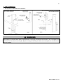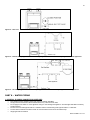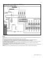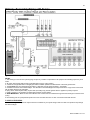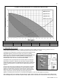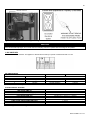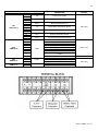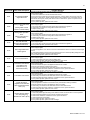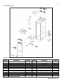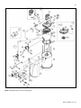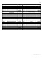
1
Gas Fired Residential Combi Boiler Floor Mount INSTALLATION / START-UP MAINTENANCE / PARTS WARRANTY Models WBRCNG140F WBRCLP140F Heat Exchanger Bears the ASME “H” Stamp NOTICE: Westinghouse reserves the right to make product changes or updates without notice and will not be held liable for typographical errors in literature. NOTE TO CONSUMER: PLEASE KEEP ALL INSTRUCTIONS FOR FUTURE REFERENCE. The surfaces of these products contacted by consumable water contain less than 0.25% lead by weight, as required by the Safe Drinking Water Act, Section 1417. IF THE INFORMATION IN THIS MANUAL IS NOT FOLLOWED EXACTLY, A FIRE OR EXPLOSION MAY RESULT, CAUSING PROPERTY DAMAGE, PERSONAL INJURY, OR LOSS OF LIFE. DO NOT STORE GASOLINE OR OTHER FLAMMABLE VAPORS AND LIQUIDS IN THE VICINITY OF THIS OR ANY OTHER APPLIANCE. WHAT TO DO IF YOU SMELL GAS Do not try to light any appliance. Do not touch any electrical switch. Do not use any phone in your building. Immediately call your gas supplier from a neighbor’s phone. Follow the gas supplier’s instructions. If you cannot reach your gas supplier, call the fire department. Installation and service must be provided by a qualified installer, service agency, or the gas supplier. WHL-015 REV. 12.17.14 2 WHL-015 REV. 12.17.14 3 The following defined terms are used throughout this manual to bring attention to the presence of hazards of various risk levels, or to important product information. DANGER indicates an imminently hazardous situation which, if not avoided, will result in death or serious injury. WARNING indicates a potentially hazardous situation which, if not avoided, could result in death or serious injury. CAUTION indicates a potentially hazardous situation which, if not avoided, may result in minor or moderate injury. CAUTION used without the safety alert symbol indicates a potentially hazardous situation which, if not avoided, may result in property damage. NOTICE NOTICE is used to address practices not related to personal injury. SAFETY INSTRUCTIONS SAFETY INSTRUCTIONS (or equivalent) signs indicate specific safety related instructions or procedures. NOTE: Contains additional information important to a procedure. WHL-015 REV. 12.17.14 4 FOREWORD This manual is intended to be used in conjunction with other literature provided with the appliance. This includes all related control information. It is important that this manual, all other documents included with this system, and additional publications including the National Fuel Gas Code, ANSI Z223.1-2002, be reviewed in their entirety before beginning any work. Installation should be made in accordance with the regulations of the Authority Having Jurisdiction, local code authorities, and utility companies which pertain to this type of water heating equipment. Authority Having Jurisdiction (AHJ) – The Authority Having Jurisdiction may be a federal, state, local government, or individual such as a fire chief, fire marshal, chief of a fire prevention bureau, labor department or health department, building official or electrical inspector, or others having statutory authority. In some circumstances, the property owner or his/her agent assumes the role, and at government installations, the commanding officer or departmental official may be the AHJ. NOTE: Westinghouse reserves the right to modify product technical specifications and components without prior notice. FOR THE INSTALLER This manual must only be used by a qualified heating installer/service technician. Read all instructions in this manual before installing. Perform steps in the order given. Failure to comply could result in substantial property damage, severe personal injury, or death. This appliance must be installed by qualified and licensed personnel. The installer should be guided by the instructions furnished with the appliance, and with local codes and utility company requirements. In the absence of local codes, preference should be given to the National Fuel Gas Code, ANSI Z223.1-2002. INSTALLATIONS MUST COMPLY WITH: Local, state, provincial, and national codes, laws, regulations and ordinances. The latest version of the National Fuel Gas Code, ANSI Z223.1, from American Gas Association Laboratories, 8501 East Pleasant Valley Road, Cleveland, OH 44131. In Canada – CGA No. B149 (latest version), from Canadian Gas Association Laboratories, 55 Scarsdale Road, Don Mills, Ontario, Canada M3B 2R3. Also, Canadian Electrical Code C 22.1, from Canadian Standards Association, 5060 Spectrum Way, Suite 100, Mississauga, Ontario, Canada L4W 5N6. Code for the installation of Heat Producing Appliances (latest version), from American Insurance Association, 85 John Street, New York, NY 11038. The latest version of the National Electrical Code, NFPA No. 70. NOTE: The gas manifold and controls met safe lighting and other performance criteria when the appliance underwent tests specified in ANSI Z21.13 – latest edition. The hydronic supply and return connections of these products are for installation in closed loop systems ONLY! Use of this product in any manner other than described in this manual may result in premature product failure, substantial property damage, severe personal injury, or death. Damage or failure of this product (or the system in which it is installed) due to unauthorized use IS NOT COVERED BY WARRANTY. TABLE OF CONTENTS PART 1 – ITEMS SHIPPED WITH THE APPLIANCE ................................................................................................................. 7 PART 2 – SAFETY REGULATIONS ........................................................................................................................................... 8 A. OPERATION AND INSTALLATION WARNINGS ....................................................................................................................... 8 B. IMPROPER COMBUSTION ....................................................................................................................................................... 9 C. GAS .......................................................................................................................................................................................... 10 D. WHEN SERVICING THE APPLIANCE..................................................................................................................................... 10 WHL-015 REV. 12.17.14 5 E. WATER QUALITY .................................................................................................................................................................... 10 F. FREEZE PROTECTION ........................................................................................................................................................... 10 PART 3 – TECHNICAL SPECIFICATIONS ............................................................................................................................... 11 PART 4 – PREPARE APPLIANCE LOCATION ........................................................................................................................ 13 A. UNCRATING THE APPLIANCE ............................................................................................................................................... 13 B. BEFORE LOCATING THE APPLIANCE .................................................................................................................................. 14 C. LEVELING ................................................................................................................................................................................ 15 D. CLEARANCES FOR SERVICE ACCESS ................................................................................................................................ 16 E. RESIDENTIAL GARAGE, CLOSET, AND ALCOVE INSTALLATIONS .................................................................................... 16 F. EXHAUST VENT AND INTAKE PIPE ....................................................................................................................................... 17 G. PREVENT COMBUSTION AIR CONTAMINATION ................................................................................................................. 17 H. REMOVING A APPLIANCE FROM A COMMON VENT SYSTEM ........................................................................................... 17 PART 5 – VENTING ................................................................................................................................................................... 18 A. INTAKE PIPE AND EXHAUST VENT GUIDELINES ................................................................................................................ 18 B. APPROVED VENT MATERIALS .............................................................................................................................................. 20 C. ALLOWED COMBINED VENT LENGTHS ............................................................................................................................... 20 D. TIGHTENING APPLIANCE COLLAR TO EXHAUST VENT AND INTAKE PIPE ..................................................................... 21 E. VENT TERMINATION .............................................................................................................................................................. 22 1. Two Pipe Roof and Sidewall Vent Terminations ..................................................................................................................... 22 2. Direct Vent, Optional Horizontal and Vertical Vent Kits ......................................................................................................... 23 3. Screen Installation ..................................................................................................................................................................... 23 PART 6 – INSTALL THE CONDENSATE DRAIN ..................................................................................................................... 24 PART 7 – GAS PIPING .............................................................................................................................................................. 25 A. GAS PIPE SIZING TABLES ..................................................................................................................................................... 25 1. Gas Pipe Sizing .......................................................................................................................................................................... 25 2. Natural Gas Pipe Sizing ............................................................................................................................................................ 25 3. LP (Liquid Propane) Gas Pipe Sizing ....................................................................................................................................... 26 B. GAS CONNECTION REQUIREMENTS ................................................................................................................................... 26 PART 8 – WATER PIPING ........................................................................................................................................................ 27 A. GENERAL PLUMBING CONNECTION GUIDELINES ............................................................................................................. 27 B. DHW PIPING ............................................................................................................................................................................ 28 C. CENTRAL HEATING PIPING SYSTEM WATER PIPING METHODS ..................................................................................... 29 D. CIRCULATOR SIZING ............................................................................................................................................................. 32 E. PRESSURE RELIEF VALVE .................................................................................................................................................... 33 PART 9 – CONNECT ELECTRICAL POWER / INITIAL STARTUP ......................................................................................... 34 A. GENERAL OPERATING CONDITIONS ................................................................................................................................... 34 B. WIRING INFORMATION .......................................................................................................................................................... 34 C. DIP SWITCHES ....................................................................................................................................................................... 35 PART 10 – OPERATING SYSTEM INSTRUCTIONS ................................................................................................................ 40 A. CONTROL PANEL ................................................................................................................................................................... 40 B. LCD DISPLAY DESCRIPTIONS .............................................................................................................................................. 40 WHL-015 REV. 12.17.14 6 C. START-UP SEQUENCE .......................................................................................................................................................... 40 D. CHANGING THE DHW SET-POINT ........................................................................................................................................ 41 E. CHANGING THE TEMPERATURE INDICATOR ..................................................................................................................... 41 F. CHANGING THE CH SET-POINT ............................................................................................................................................ 41 G. STORAGE MODE .................................................................................................................................................................... 42 H. STATUS DISPLAY MODE ....................................................................................................................................................... 42 I. INSTALLER MODE .................................................................................................................................................................... 43 J. ERROR MODE ......................................................................................................................................................................... 45 K. ERROR TREE ANALYSIS ........................................................................................................................................................ 48 1. FLAME DETECTION ................................................................................................................................................................... 48 2. GAS DETECTION ....................................................................................................................................................................... 48 3. APS / BURNER OVERHEAT LIMIT / CONDENSATE BLOCK SWITCH ................................................................................... 49 4. STORAGE / DHW / OP / CH OVERHEAT / EXHAUST OVERHEAT SENSORS ....................................................................... 49 L. OUTDOOR TEMPERATURE MODE (OPTIONAL)................................................................................................................... 49 M. 0-10 VOLT INPUT .................................................................................................................................................................... 50 PART 11 – START-UP PREPARATION.................................................................................................................................... 51 A. CHECK / CONTROL WATER CHEMISTRY ............................................................................................................................. 51 B. CHECK FOR GAS LEAKS ....................................................................................................................................................... 51 C. FILL AND TEST WATER SYSTEM .......................................................................................................................................... 52 D. PURGE AIR FROM CH AND INTERNAL STORAGE TANK .................................................................................................... 53 E. PURGE AIR FROM DHW SYSTEM ......................................................................................................................................... 53 F. CHECK THERMOSTAT CIRCUIT(S) ....................................................................................................................................... 53 G. CONDENSATE REMOVAL ...................................................................................................................................................... 54 H. FINAL CHECKS BEFORE STARTING APPLIANCE................................................................................................................ 54 I. ADJUSTING GAS PRESSURE AT THE APPLIANCE ............................................................................................................... 54 J. SETTING AND VERIFYING THE COMBUSTION SETTING .................................................................................................... 55 PART 12 –INSTALLATION AND START-UP CHECKLIST ...................................................................................................... 56 PART 13 – TROUBLESHOOTING ............................................................................................................................................ 57 PART 14 – ANNUAL MAINTENANCE PROCEDURES ............................................................................................................ 58 REPLACEMENT PARTS ................................................................................................................................................................ 63 Limited Warranty for Combination Appliances ........................................................................................................................... 66 MAINTENANCE REPORT .............................................................................................................................................................. 68 MAINTENANCE NOTES ................................................................................................................................................................. 72 CUSTOMER INSTALLATION RECORD FORM ............................................................................................................................. 73 WHL-015 REV. 12.17.14 7 PART 1 – ITEMS SHIPPED WITH THE APPLIANCE ITEM Residential Floor Mount Combi Boiler DESCRIPTION QUANTITY 1 Installation and User’s Information Manuals, H2 Document 1 Each Condensate Hose 1 Condensate Adapters and Instruction Sheet 1 kit CH Pressure Relief Valve With ¾” X 1” Bushing (CH Line ¾” 30 psi) 1 Each. Vent Screens (3”) 2 Screens Outdoor Sensor with Screws and Anchors 1 3” CPVC 6” Length ½” X ¾” Bell Coupling for Gas Line 1 Spare Parts Kit (Gaskets and O-Rings) 1 Propane (LP) Conversion Kit 1 WHL-015 REV. 12.17.14 8 ITEM OPTIONAL PARTS (Not Included) DESCRIPTION QUANTITY PART NUMBER Threaded 1” CH Tankless Isolation Valves 2 7850P-089 Threaded ¾” DHW Tankless Isolation Valves 2 7850P-090 Vent Screens (2” Mesh) 2 Screens 7850P-088 Table 1 – Items Included with the Appliance PART 2 – SAFETY REGULATIONS A. OPERATION AND INSTALLATION WARNINGS To avoid serious injury or death, read, understand, and follow all the precautions listed here. Vapors from flammable liquids will explode and can cause a fire, resulting in personal injury or death. The appliance has a burner that can come on at any time and ignite vapors. DO NOT use or store flammable liquids around the appliance. Improper venting can cause a build-up of carbon monoxide. Breathing carbon monoxide can result in brain damage or death. DO NOT operate the appliance unless it is properly vented to the outside and has an adequate fresh air supply for safe operation. Inspect the exterior exhaust gas outlet port and fresh air inlet port on a regular basis to ensure they are functioning properly. A concentration of carbon monoxide as small as .04% (400 parts per million) in the air can be fatal. When making high fire or low fire adjustments, CO levels must be monitored using a flue gas analyzer such that a CO level of no more than 400 ppm is exceeded at any time during operation. Adjusting the “low fire offset” on the gas valve in even small increments can result in a significant increase in CO concentration. To avoid serious injury or death, DO NOT make any adjustments to the gas valve without monitoring the exhaust gases with a fully functional and calibrated flue gas analyzer. Failure to follow these statements will result in property damage, severe personal injury, or death. This appliance must be installed by a licensed plumber, licensed gas fitter, and/or professional service technician. Improper installation and/or operation can cause a potentially hazardous situation, which, if not avoided, could result in serious injury or death, and will void the warranty. Westinghouse cannot anticipate every circumstance that might involve a potential hazard. Each installation has its own specialized characteristics, requirements, and possible hazards. Therefore, all possible incidents are not included in these warnings. Proper and safe installation, operation, and service are the responsibility of the professional service technician. Proper care of the appliance is the user’s responsibility. Ensure the user carefully reads and understands the User’s Information Manual before operating and maintaining the appliance. Make sure the user knows the location of the gas shut-off valve and how to operate it. Immediately close the gas shut-off valve if the appliance is subjected to fire, overheating, flood, physical damage, or any other damaging condition that might affect the operation of the unit. Have the appliance checked by a qualified technician before resuming operation. Do not power up the unit unless the gas and water supply valves are fully opened. Make sure the fresh air intake port and exhaust gas port are open and functional. No one but a professional service technician should attempt to install, service, or repair this appliance. There are no serviceable parts which can be changed by the user / owner. User / Owner: Contact the original professional service technician if the appliance needs repair or maintenance. If the original technician is unavailable, ask your gas supplier for a list of qualified service providers. Keep the area around the appliance clean and free of all materials that can burn. DO NOT store or place gasoline, oils, spray paint, or other flammable products near the appliance. WHL-015 REV. 12.17.14 9 DO NOT use spray paint, hair spray, or any other flammable spray near the appliance or near the exterior fresh air intake port. DO NOT place any items in or around the exterior exhaust gas outlet port and/or fresh air inlet port that could restrict or block the flow in or out of the vent system. DO NOT store or place newspapers, laundry, or other combustible items near the appliance or the exterior exhaust gas outlet and/or fresh air inlet port. The owner should inspect the system monthly for damage, water stains, signs of rust, corrosion, and exhaust vent and air intake blockage. If inspection of the unit shows signs of damage, the appliance should be shut off until the problem is repaired by a qualified technician. After installation, all appliance safety devices should be tested. This appliance is certified for indoor installations only. The appliance consists of gas ignition system components which must be protected from water (dripping, spraying, etc.) during operation and service. Carefully consider installation location and the placement of critical components (circulators, condensate neutralizers, etc.) before installing the appliance. DO NOT allow children to operate this unit. DO NOT use this unit if it does not appear to be operating correctly. A qualified technician should service and inspect the appliance annually. o o The appliance DHW temperature is factory set to 125 F (51 C). To avoid scalding, always check the temperature of the hot water before bathing, showering, washing, etc. DO NOT adjust the water temperature while the appliance is being used by other persons. If the appliance is exposed to the following, do not operate until all corrective steps have been made by a qualified service technician: 1. FIRE 2. DAMAGE 3. WATER This appliance is equipped with a three prong plug. It should only be plugged directly into a properly grounded three prong receptacle. DO NOT remove the ground plug from the plug. DO NOT alter or modify the appliance or appliance controls. This can be dangerous and WILL VOID the warranty. Failure to follow these statements could result in property damage, severe personal injury, or death. NOTICE Any claims for damage or shortage in shipment must be filed immediately against the transportation company by the consignee. This appliance provides a overheat shutdown limit. In the event the appliance water exceeds the set point of the control limit, the cutoff will trip and the appliance will shut down. Certain local codes require additional temperature limits. In addition, certain types of systems may operate at temperatures below the minimum set point of the limit provided with the appliance. Contact a qualified service technician for additional overheat controls. NOTE: When inquiring about service or troubleshooting, reference the model and serial numbers from the appliance rating label. DO NOT USE THIS APPLIANCE IF ANY PART HAS BEEN SUBMERGED IN WATER. Immediately call a qualified service technician. The appliance MUST BE replaced if it has been submerged. Attempting to operate an appliance that has been submerged could create numerous harmful conditions, such as a potential gas leakage causing a fire and/or explosion, or the release of mold, bacteria, or other harmful particulates into the air. Operating a previously submerged appliance could result in property damage, severe personal injury, or death. NOTE: Appliance damage due to flood or submersion is considered an Act of God, and IS NOT covered under product warranty. Be sure to disconnect electrical power before opening appliance cabinet or performing service. Label all wires while performing service to ensure proper re-wiring of the appliance. Wiring errors can cause improper or dangerous operation. Failure to do so could result in an electrical shock, improper appliance operation, property damage, serious personal injury, or death. Due to the low water content of the appliance, improper sizing of the appliance with regard to heating system load will result in excessive cycling and accelerated component failure. Westinghouse DOES NOT warrant failures caused by improperly sized appliance applications. DO NOT oversize the appliance to the system. Modular appliance installations greatly reduce the likelihood of appliance oversizing. B. IMPROPER COMBUSTION Do not obstruct the flow of combustion and ventilating air. Adequate air must be provided for safe operation. Failure to keep the exhaust vent and intake pipe clear of ice, snow, or other debris could result in property damage, serious personal injury, or death. WHL-015 REV. 12.17.14 10 C. GAS Should overheating or gas supply fail to shut off, do not turn off or disconnect electrical supply to the circulator. Instead, shut off the gas supply at a location external to the appliance. D. WHEN SERVICING THE APPLIANCE To avoid electric shock, disconnect electrical supply before performing maintenance. To avoid severe burns, allow appliance to cool. Do not use petroleum-based cleaning or sealing compounds in a appliance system. Gaskets and seals in the system may be damaged, possibly resulting in substantial property damage. Do not use “homemade cures” or “patent medicines”. Substantial property damage, damage to appliance, and/or serious personal injury may result. Always verify proper operation after servicing the appliance. E. WATER QUALITY Potable water is defined as drinkable water supplied from utility or well water in compliance with EPA secondary maximum contaminant levels (40 CFR Part 143.3) as shown in Table 2. It is important to ensure the water quality is within these determined limits. If your water contains contaminants higher than outlined by EPA, then water treatment is recommended and additional maintenance may be required. If you suspect that your water is contaminated in any way, discontinue use of the appliance and contact an authorized technician or licensed professional. Contaminant Maximum Allowable Level Total Hardness 200 mg/l (12 grains/gallon) Aluminum 0.05 to 0.2 mg/l Chloride 250 mg/l Copper 1 mg/l Iron 0.3 mg/l Table 2 – Water Quality Specifications Contaminant Manganese pH Sulfate Total Dissolved Solids (TDS) Zinc Maximum Allowable Level 0.05 mg/l 6.5-8.5 205 mg/l 500 mg/l 205 mg/l F. FREEZE PROTECTION Consider appliance piping and installation when determining appliance location. NOTE: Damages resulting from incorrect installation or from use of products not approved by Westinghouse ARE NOT covered by warranty. WHL-015 REV. 12.17.14 11 PART 3 – TECHNICAL SPECIFICATIONS MODEL Installation Minimum / Maximum Input (Btu/Hr) AFUE o 35 F Rise o Hot Water Capacity 45 F Rise o 77 F Rise Flue System Combined Vent Length Shipping Weight (lbs est.) NG Orifice Size LP NG Gas Supply Pressure LP Min (2” / 3” Vent) Manifold Pressure Max (2” / 3” Vent) Main Supply Power Supply Maximum Power Consumption Ignition System Burner System Gas Valve System Internal Pipe Material Dimensions Storage Tank Water Capacity (DHW) Main Controller / Control Panel CH Pressure DHW Pressure DHW Inlet / Hot Water Outlet Connection CH Supply / Return Sizes Gas Inlet Cabinet Materials Heat Exchanger Safety Devices Residential Combi Boiler Indoor, Floor Stand, Fully Condensing 28,000 / 140,000 92.7% 7.1 Gal 5.5 Gal 3.2 Gal Sealed Combustion Direct Vent 2” (50 feet), 3” (100 feet) 250 0.232” (5.9 mm) 0.185” (4.7 mm) 3.5” to 14” WC 3.5” to 14” WC NG: -0.0039” / -0.002” WC NG: -0.374” / -0.216” WC 120V 60 Hz / 6A 160W Direct Electronic Ignition / Automatic Flame Sensing Single Orifice Premixed Fuel Modulation Ceramic Fiber Infrared Combination Modulating (Current Proportional) Copper W 15.7” – H 53” – D 26.8” Under 15 Gallons GTX-920C / P-920C_CB-HTP Min 15 PSI - Max 30 PSI Max 150 PSI ¾” NPT 1” NPT ½” NPT (1/2” X ¾” Bell Coupling Provided to Upsize Gas Line) Cold Rolled Carbon Steel Primary Heat Exchanger: Stainless Steel Storage Tank: Stainless Steel Flame Rod, Overheat Cut Off Device, Gas Valve Operation Detector, Exhaust Temperature High Limit Sensor, Water Temperature High Limit Sensor Table 3 – Technical Specifications WHL-015 REV. 12.17.14 12 Figure 1 – Specifications and Dimensions DESCRIPTION A Gas Connection Adapter B CH Supply Adapter C CH Return Adapter D DHW Outlet Adapter E DHW Inlet Adapter F Condensate Adapter G Drain Adapter H Exhaust Vent Connection I Intake Pipe Connection Table 4 – Adapter Specifications DIAMETER (ALL NPTM) ½” NPT (½” X ¾” Bell Coupling Provided to Upsize Gas Line) 1” 1” ¾” ¾” ½” ½” 3” 3” WHL-015 REV. 12.17.14 13 Figure 2 – Components NUMBER COMPONENT DESCRIPTION 1 Exhaust Vent Adapter 2 BLDC Fan 3 Flame Detection Window 4 Main PCB 5 Flame Detection Sensor 6 Control Panel 7 Manual ON/OFF Power Switch 8 Exhaust Pipe 9 Internal CH Pump 10 Mixing Valve 11 Internal Recirculation Pump (DHW) 12 Water Discharge Adapter 13 Water Discharge Valve 14 Internal Storage Tank 15 Condensate Trap Adapter 16 Condensate Hose 1 Table 5 – Component List NUMBER 17 18 19 20 21 22 23 24 25 26 27 28 29 30 31 COMPONENT DESCRIPTION Condensate Trap DHW Inlet Adapter DHW Outlet Adapter Condensate Hose 2 CH Return Adapter APS (Air Pressure Switch) CH Supply Adapter Heat Exchanger Gas Inlet Adapter Gas Valve Air Vent Ignition Transformer Igniter Air Intake Pipe Air Intake Adapter PART 4 – PREPARE APPLIANCE LOCATION A. UNCRATING THE APPLIANCE UNCRATING APPLIANCE – Any claims for damage or shortage in shipment must be filed immediately against the transportation company by the consignee. WHL-015 REV. 12.17.14 14 o Cold weather handling – If appliance has been stored in a very cold location (below 0 F) before installation, handle with care until the plastic components come to room temperature. Remove all sides of the shipping crate to allow the appliance to be lifted into its installation location. If surface flooring is rough, take care when sliding appliance into position, as you could damage the appliance. Carefully consider installation when determining appliance location. Please read the entire manual before attempting installation. Failure to properly take factors such as appliance venting, piping, condensate removal, and wiring into account before installation could result in wasted time, money, and possible property damage and personal injury. B. BEFORE LOCATING THE APPLIANCE Incorrect ambient conditions can lead to damage to the heating system and put safe operation at risk. Ensure that the appliance installation location adheres to the information included in this manual. Failure to do so could result in property damage, serious personal injury, or death. Failure of appliance or components due to incorrect operating conditions IS NOT covered by product warranty. 1. Installation Area (Mechanical Room) Operating Conditions o o o o Ensure ambient temperatures are higher than 32 F/0 C and lower than 104 F/40 C. Prevent the air from becoming contaminated by the products, places, and conditions listed in this manual. Avoid continuously high levels of humidity Never close existing ventilation openings The service life of the appliance’s exposed metallic surfaces, such as the casing, as well as internal surfaces, such as the heat exchanger, are directly influenced by proximity to damp and salty marine environments. In such areas, higher concentration levels of chlorides from sea spray coupled with relative humidity can lead to degradation of the heat exchanger and other appliance components. In these environments, appliances must not be installed using direct vent systems which draw outdoor air for combustion. Such appliances must be installed using room air for combustion. Indoor air will have a much lower relative humidity and, hence, potential corrosion will be minimized. This appliance is certified for indoor installations only. Do not install the appliance outdoors. Failure to install this appliance indoors could result in substantial property damage, severe personal injury, or death. 2. Check for nearby connections to: System water piping Venting connections Gas supply piping Electrical power Condensate drain Locate the appliance where any leakage from the relief valve, related piping, tank, or connections will not result in damage to surrounding areas or lower floors of the building. The appliance should be located near a floor drain, or installed in an adequately drained drain pan. Westinghouse WILL NOT be held liable for leakage damages. To conserve water and energy, insulate all water piping, especially the hot and recirculation water lines. 3. Check area around appliance. Remove any combustible materials, gasoline, and other flammable liquids. Failure to keep appliance area clear and free of combustible materials, liquids, and vapors can result in substantial property damage, severe personal injury, or death. WHL-015 REV. 12.17.14 15 4. Gas control system components must be protected from dripping water during operation and service. 5. If the appliance is to replace an existing appliance, check for and correct any existing system problems, such as: System leaks Location that could cause the system and appliance to freeze and leak. Incorrectly-sized expansion tank Do not connect the appliance to any heating systems or components that have been previously used for non-potable applications. Do not introduce toxic chemicals, such as antifreeze or appliance treatments, into the appliance or any piping meant for potable water purposes. Ensure that all piping and components connected to the appliance are suitable for potable water applications. Do not use this appliance only for space heating applications. Circulators suitable for DHW applications must be used. Failure to follow these instructions could result in property damage, personal injury, or death. 6. Clean and flush system when reinstalling an appliance. NOTE: When installing in a zero clearance location, it may not be possible to read or view some product labeling. It is recommended to make note of the appliance model and serial number. C. LEVELING In order for the condensate to properly flow out of the collection system, the appliance must be installed level. Failure to ensure the appliance is installed level will result in improper appliance operation. Figure 3 – Proper Leveling WHL-015 REV. 12.17.14 16 D. CLEARANCES FOR SERVICE ACCESS See Figure 4 and Table 6 for recommended service clearances. If these minimum clearances are not provided, it may not be possible to service the appliance without removing it from the space. Space must be provided with combustion/ventilation air openings correctly sized for all other appliances located in the same space as the appliance. The appliance cover must be securely fastened to prevent it from drawing air from the appliance room. This is particularly important if the appliance is in a room with other appliances. Failure to comply with the above could result in substantial property damage, severe personal injury, or death. MINIMUM CLEARANCES Installation Clearances Recommended Service and Proper from Non-Combustibles / Operation Clearances Combustibles Top 18 in. (45.7 cm) Back 0 in. (0 cm) Front 24 in. (60.9 cm) Right Side Left Side 6 in. (15.2 cm) Table 6 – Minimum Installation and Service Clearances NOTE: For closet installations, a combustible door or removable panel is acceptable front clearance. Figure 4 – Minimum Service Clearances MINIMUM CLEARANCES FROM COMBUSTIBLE MATERIALS Hot water pipes – at least 1” from combustible materials. Exhaust vent pipe – at least 1” from combustible materials. Always take future maintenance into consideration when locating the appliance. If the appliance is located in an installation location with limited clearances, it may be necessary to remove the appliance from the space to perform maintenance. Failure to consider maintenance when determining installation location could result in property damage. E. RESIDENTIAL GARAGE, CLOSET, AND ALCOVE INSTALLATIONS Check with your local Authority Having Jurisdiction for requirements when installing boiler in a garage, closet, or alcove. Please read the entire manual before attempting installation. Failure to properly take factors such as boiler venting, piping, condensate removal, and wiring into account before installation could result in wasted time, money, and possible property damage and personal injury. PRECAUTIONS If the boiler is located in a residential garage, it should be installed per the latest edition of the National Fuel Gas Code, ANSI Z223.1, and CGA-B149 Installation Code in Canada. Mount the bottom of the boiler a minimum of 18” above the floor of the garage, to ensure the burner and ignition devices are well off the floor. Locate or protect the boiler so it cannot be damaged by a moving vehicle. For closet or alcove installations, a two pipe venting system must be used. Failure to follow this warning could result in substantial property damage, severe personal injury, or death. The space must be provided with correctly sized combustion/ventilation air openings for all other boilers located in the space with the boiler. Do not install the boiler in an attic. Failure to comply with these warnings could result in substantial property damage, severe personal injury, or death. WHL-015 REV. 12.17.14 17 F. EXHAUST VENT AND INTAKE PIPE Vents must be properly supported. The appliance exhaust and intake connections are not designed to carry heavy weight. Vent support brackets must be within 1’ of the appliance and the balance at 4’ intervals. Venting must be readily accessible for visual inspection for the first 3’ from the appliance. The appliance is rated ANSI Z21.13 Category IV (pressurized vent, likely to form condensate in the vent), and requires a special vent system designed for pressurized venting. You must also install air intake piping from outdoors to the appliance flue adaptor. The resultant installation is categorized as direct vent (sealed combustion). NOTE: To prevent combustion air contamination, see Table 7 in this section when considering exhaust vent and intake pipe termination. Exhaust vent and intake pipe may be vented vertically through the roof or out a side wall. Venting methods are detailed in the Venting Section. Do not attempt installation using any other means. Be sure to locate the appliance so exhaust vent and intake piping can be routed through the building and properly terminated. Exhaust vent and intake piping lengths, routing, and termination method must comply with methods and limits given in the venting section. G. PREVENT COMBUSTION AIR CONTAMINATION Install intake piping for the appliance as described in the Venting section. Do not terminate exhaust in locations that can allow contamination of intake air. Ensure that the intake air will not contain any of the contaminants below. For example, do not pipe intake near a swimming pool. Avoid areas subject to exhaust fumes from laundry facilities. These areas always contain contaminants. Contaminated air will damage the appliance, resulting in possible substantial property damage, severe personal injury, or death. PRODUCTS TO AVOID Spray cans containing fluorocarbons Permanent wave solutions Chlorinated waxes/cleaners Chlorine-based swimming pool chemicals Calcium chloride used for thawing Sodium chloride used for water softening Refrigerant leaks Paint or varnish removers Hydrochloric or Muriatic acid Cements and glues Antistatic fabric softeners used in clothes dryers Chlorine-type bleaches, laundry detergents, and cleaning solvents Adhesives used to fasten building products Table 7 AREAS LIKELY TO HAVE CONTAMINANTS Dry cleaning/laundry areas and establishments Swimming pools Metal fabrication plants Beauty shops Refrigeration repair shops Photo processing plants Auto body shops Plastic manufacturing plants Furniture refinishing areas and establishments New building construction Remodeling areas Garages and workshops NOTE: DAMAGE TO THE APPLIANCE CAUSED BY EXPOSURE TO CORROSIVE VAPORS IS NOT COVERED BY WARRANTY. (Refer to the limited warranty for complete terms and conditions). H. REMOVING A APPLIANCE FROM A COMMON VENT SYSTEM Do not install the appliance into a common vent with any other appliance. This will cause flue gas spillage or appliance malfunction, resulting in possible substantial property damage, severe personal injury, or death. Failure to follow all instructions can result in flue gas spillage and carbon monoxide emissions, causing severe personal injury or death. When removing an existing appliance, the following steps must be followed. 1. Seal any unused openings in the common venting system. WHL-015 REV. 12.17.14 18 2. Visually inspect the venting system for proper size and horizontal pitch to determine if there is blockage, leakage, corrosion or other deficiencies that could cause an unsafe condition. 3. If practical, close all building doors, windows and all doors between the common venting system and other spaces in the building. Turn on clothes dryers and any appliances not connected to the common venting system. Turn on any exhaust fans, such as range hoods and bathroom exhausts, at maximum speed. Do not operate a summer exhaust fan. Close all fireplace dampers. 4. Place in operation the appliance being inspected. Follow the lighting instructions. Adjust the thermostat so the appliance will operate continuously. 5. Test for spillage at the draft hood relief opening after 5 minutes of main burner operation. Use the flame of a match or candle or smoke from a cigarette. 6. After it has been determined that each appliance remaining connected to common venting system properly vents when tested as outlined, return doors, windows, exhaust fans, fireplace dampers and any other gas burning appliance to their previous condition of use. Figure 5 - CO Warning Label 7. Any improper operation of the common venting system should be corrected so the installation conforms to the National Fuel Gas Code, ANSI Z223.1. When resizing any portion of the common venting system, the common venting system should be resized to approach the minimum size as determined using the appropriate tables in Appendix G in the National Fuel Gas Code, ANSI Z 223.1. PART 5 – VENTING Vent this appliance in accordance with these instructions. Failure to do so will result in property damage, severe personal injury, or death. DO NOT mix vent systems or materials unless specifically told to do so in this manual. DO NOT thermally insulate the exhaust vent or intake pipes. DO NOT use an electric damper, vent damper, or draft hood with this appliance. DO NOT locate the exhaust vent or intake pipe terminations where exposed to prevailing winds. Moisture will be produced by the exhaust vent. Take precautions when determining exhaust vent termination. Moisture may fall from the vent termination to the ground and turn to ice in freezing conditions. Moisture or ice can produce a hazardous condition. Exhaust condensate is acidic, and could deteriorate the surface below the exhaust vent termination. Ensure this surface is in good repair (sealed, painted, etc.) to prevent deterioration. Pitch the exhaust vent pipe ¼” back to the appliance. This ensures that condensate in the exhaust vent returns to the appliance and drains properly. For closet and alcove installations: CPVC, polypropylene, or stainless steel venting material MUST BE USED. Failure to follow this statement could result in product damage, severe personal injury, or death. Failure to follow these instructions could result in property damage, severe personal injury, or death. A. INTAKE PIPE AND EXHAUST VENT GUIDELINES 1. Vent system must be installed in accordance with local codes, or, in absence of local codes, the National Fuel Gas Code, ANSI Z223.1 / NFPA 54 and/or CSA B149.1, Natural Gas and Propane Installation Code. 2. For installation in Canada, installer supplied plastic vent piping must comply with CAN/CGA B149.1 and be certified to the Standard for Type BH Gas Venting Systems, ULC-S636. Components of this listed system must not be interchanged with other vent systems or unlisted pipes or fittings. All plastic components and specified primers and glues must be from a single system manufacturer and must not be intermixed with another system manufacturer’s products. Clean and dry all applicable surfaces before applying cement. 3. This appliance is designed to be installed as a direct vent (sealed combustion) type. Combustion air must be supplied directly from the outdoors to the burner, and the flue (exhaust) gases should be vented directly to the outdoors through the wall or roof. WHL-015 REV. 12.17.14 19 4. This appliance uses 2” or 3” diameter pipe for exhaust vent and intake pipe. It is important to ensure an airtight seal from the appliance collar to the vent terminations. See Table 9 for a list of Approved Vent Materials. 5. Do not install venting system components on the exterior of the building except as specifically required by these instructions. Vent terminals must be at least 1 foot from any door, window, or gravity inlet into the building. Maintain the correct clearance and orientation between the exhaust vent and intake pipe terminals. The exhaust vent and air intake terminals must be at the same height and their center lines must be spaced apart 1 foot minimum. The bottom of the exhaust vent and intake pipe terminals must be at least 1 foot above the normal snow accumulation level. In no case should these terminals be installed less than 1 foot above normal snow accumulation level. Do not install the exhaust vent terminals directly above windows or doors. Intake pipe terminal must not terminate in areas that might contain combustion air contaminates, such as near swimming pools. For sidewall venting, the minimum horizontal distance between adjacent exhaust vent terminations is 1 foot. It is recommended this distance be greater than 1 foot to better avoid frost damage to building surfaces. For roof venting, minimum horizontal distance between any adjacent exhaust vent termination is 1 foot. Figure 6 – Vent Termination Detail A B C D E F G H I J DESCRIPTION Clearance above grade, veranda, porch, deck, or balcony Clearance to window or door that may be opened Clearance to permanently closed window Vertical clearance to ventilated soffit located above the terminal within a horizontal distance of 2 feet from the center line of the terminal Clearance to unventilated soffit Clearance to outside corner Clearance to inside corner Clearance to each side of center line extended above meter / regulator assembly Clearance to service regulator vent outlet Clearance to non-mechanical air supply inlet to building or the combustion air inlet to any other appliance US 1 foot 1 foot * CANADA 1 foot 3 feet * * * * * * * * * * 3 feet with a height 15 feet above meter / regulator assembly 3 feet 1 foot 3 feet * 3 feet above if within 10 feet 6 feet horizontally L Clearance above paved sidewalk or driveway located * 7 feet M Clearance under veranda, porch, deck, or balcony * 1 foot Table 8 – Vent Termination Clearances - *NOTE: For clearances not specified in ANSI Z223.1/NFPA 54 or CAN/CSA-B 149.1, please use clearances in accordance with local installation codes and the requirements of the gas supplier. K Clearance to a mechanical air supply inlet WHL-015 REV. 12.17.14 20 B. APPROVED VENT MATERIALS NOTICE Consult Table 9 or the most recent edition of ANSI Z223.1/NFPA 54 or CAN/CGA B149.1 as well as all applicable local codes and regulations when selecting vent pipe materials. Item Exhaust vent or Intake pipe and fittings Pipe cement/primer APPROVED EXHAUST VENT AND INTAKE PIPE MATERIAL Standards for Installation in: Material United States Canada CPVC schedule 40 ASTM-D2846 PP, CPVC, and PVC venting must be ULC-S636 Certified. IPEX is an approved PVC schedule 40 ANSI/ASTM D1785 manufacturer in Canada, supplying vent Polypropylene ULCS636 material listed to ULC-S636. Certified for Category IV and Certified for Category IV and direct vent Stainless Steel AL29-4C direct vent appliance venting appliance venting PVC ANSI/ASTM D2564 IPEX System 636 Cements & Primers CPVC ANSI/ASTM F493 The exhaust and intake components installed with this appliance must be used for near appliance piping BEFORE transitioning to the approved materials listed above. DO NOT REMOVE these installed components. Doing so WILL VOID warranty. PVC/CPVC pipe and fittings of the same diameter are considered interchangeable. DO NOT use Foam Core Pipe (CPVC cellular core, Radel, etc.) in any portion of the exhaust piping from this appliance. DO NOT connect PVC/CPVC to PP without an approved vent connector. When installing AL29-4C vent piping, install a PVC-to-stainless adapter at the appliance vent connection, and at the termination when using an PVC termination kit. DO NOT mix AL-29-4C piping from different manufacturers unless using adapters specifically designed for the purpose by the manufacturer. DO NOT insulate non-metallic exhaust vent pipe or fittings. DO NOT obstruct the flow of combustion or ventilation air. When using Pipe Cement/Primer, follow the instructions included with the Cement/Primer closely. Clean and dry all applicable surfaces before applying. Failure to follow these directions will result in substantial property damage, severe personal injury, or death. Table 9 – Approved Venting Materials Vent adaptors are not designed as load-bearing devices, and must not be used to support exhaust vent piping. All vent pipes must be properly connected, supported, and the exhaust must be pitched a minimum of ¼” per foot back to the appliance to allow drainage of condensate. Failure to properly support vent piping and follow the information in this statement could result in product damage, severe personal injury, or death. For closet and alcove installations: CPVC, polypropylene, or stainless steel venting material MUST BE USED. Failure to follow this statement could result in product damage, severe personal injury, or death. o o High heat sources (sources generating heat 100 F / 37 C or greater, such as stove pipes, space heaters, etc.) may damage plastic components of the appliance as well as plastic vent pipe materials. Such damages ARE NOT covered by warranty. It is recommended to keep a minimum clearance of 8” from high heat sources. Observe heat source manufacturer instructions, as well as local, state, provincial, and national codes, laws, regulations and ordinances when installing this appliance and related components near high heat sources. C. ALLOWED COMBINED VENT LENGTHS 2” COMBINED VENT LENGTH MAXIMUM 50’ (15M) Table 10 – Approved Vent Lengths 3” COMBINED VENT LENGTH MAXIMUM 100’ (30M) NOTE: When using more than 1 elbow, reduce maximum allowable length: o 5 feet (1.5M) for each additional 3” 90 elbow o 2.5 feet (.75M) for each additional 3” 45 elbow WHL-015 REV. 12.17.14 21 o 8 feet (2.4M) for each additional 2” 90 elbow o 4 feet (1.2M) for each additional 2” 45 elbow Vent adaptors are not designed as load-bearing devices, and must not be used to support exhaust vent piping. All vent pipes must be properly connected, supported, and the exhaust must be pitched a minimum of ¼” per foot back to the appliance to allow drainage of condensate. Failure to properly support vent piping and follow the information in this statement could result in product damage, severe personal injury, or death. D. TIGHTENING APPLIANCE COLLAR TO EXHAUST VENT AND INTAKE PIPE NOTE: The included 6” length of 3” CPVC pipe MUST BE INSTALLED in the exhaust vent connection BEFORE venting the appliance. Failure to properly install the included 6” length of 3” CPVC pipe BEFORE venting the appliance could result in product damage, severe personal injury, or death. This appliance uses 2” or 3” diameter pipe for exhaust vent and intake pipe. In order to use 2” pipe, it is required to reduce pipe size in a vertical length of pipe with a reducing coupling (not included). Follow the steps below to install 2” or 3” pipe into the appliance collar. See Figure 7 for additional details. 1. 2. 3. 4. 5. Clean and dry the appliance connection. DO NOT use primer or cement on the appliance connection. Push the included 6” length of CPVC pipe into the connection until it touches the bottom of the fitting. Tighten the clamps using a screwdriver. Ensure the pipe is secure before continuing installation. For 2” installations, install a reducing coupling in a vertical section of pipe. See Figure 8. Figure 7 – Installing the 6” Length of CPVC into the Exhaust Vent Connection Figure 8 – Transitioning from 3” to 2” Vent Pipe WHL-015 REV. 12.17.14 22 E. VENT TERMINATION 1. Two Pipe Roof and Sidewall Vent Terminations Figure 9 – Direct Vent, Roof and Sidewall Vent Terminations All vent pipes must be glued, properly supported, and the exhaust must be pitched a minimum of ¼” per foot back to the appliance to allow drainage of condensate. When placing support brackets on vent piping, the first bracket must be within 1 foot of the appliance and the balance at 4 foot intervals on the vent pipe. Appliance venting must be readily accessible for visual inspection for the first three feet from the appliance. WHL-015 REV. 12.17.14 23 2. Direct Vent, Optional Horizontal and Vertical Vent Kits Figure 10 – Direct Vent, Vent Terminations (With Optional Kits) All vent pipes must be glued, properly supported, and the exhaust must be pitched a minimum of ¼” per foot back to the appliance to allow drainage of condensate. When placing support brackets on vent piping, the first bracket must be within 1 foot of the appliance and the balance at 4 foot intervals on the vent pipe. Appliance venting must be readily accessible for visual inspection for the first three feet from the appliance. 3. Screen Installation After connecting the intake air and exhaust vent pipes, it is required to install the included screens into the exhaust vent and intake pipe terminations to prevent damages to the unit due to blockages. Clean the vent terminations and cement the screens into the terminations. See Figure 11 for installation detail. Figure 11 - Screen Installation SAFETY INSTRUCTIONS Do not connect any other appliance vents to the appliance exhaust vent or intake pipes. WHL-015 REV. 12.17.14 24 PART 6 – INSTALL THE CONDENSATE DRAIN 1. Due to its efficient design, the appliance produces condensate (water) as a normal by-product. This condensate is acidic, with a pH level between 3 and 4. This condensate must be drained away from the appliance and disposed in accordance with all local regulations. 2. Use corrosion-resistant materials approved by the Authority Having Jurisdiction (AHJ) to drain condensate. In the absence of an AHJ, the included flexible plastic hose, or field supplied ½” PVC and CPVC drain pipe complying with ASTM D1785, F441, or D2665 may be used. Cement and primer must comply with ASTM D2564 or F493. For Canadian applications, use CSA or ULC certified PVC or CPVC pipe, fittings, and cement. 3. Local building codes may require an in-line neutralizer to be installed (not included) to treat the condensate. Follow all the installation instructions included with the neutralizer. If a neutralizer is installed, periodic replacement of the limestone (or neutralizing agent) will be required. The rate of depletion of the limestone varies with usage of the appliance. During the first year of appliance operation, check the neutralizer every few months for depletion. 4. Route the drain line to a nearby floor drain, laundry tub, or condensate pump. NOTE: If a nearby laundry tub is used as a disposal for waste water from the washing machine, draining the condensate into this tub allows the soapy water discharge to neutralize the acidic condensate. 5. An error will appear on the appliance display if condensate line is blocked. The appliance will not operate with a blocked condensate line. It is extremely important to have this condition repaired by a qualified service technician. NOTE: This appliance has an internal condensate trap that must be cleaned and maintained. See Maintenance section of this manual for instructions on maintaining the trap. Figure 12 – Internal Condensate Trap Figure 13 – Condensate Piping with Condensate Neutralizer / Condensate Piping with Condensate Neutralizer and Pump NOTES: 1. Condensate line must be pitched at least 1/4" per foot to properly drain. If this cannot be done, or a very long length of condensate hose is used, you must increase the condensate line to a minimum of 1” ID and place a tee in the line after the condensate neutralizer to properly reduce vacuum lock in the drain line. 2. Plastic pipe should be the only material used for the condensate line. Steel, brass, copper, or other materials will be subject to corrosion or deterioration. 3. NEVER install condensate lines outside. It is very important that the condensate line is not exposed to freezing temperatures or any type of blockage. Damages due to frozen or blocked condensate lines ARE NOT covered by warranty. 4. Support of the condensate line may be necessary to avoid blockage of the condensate flow. WHL-015 REV. 12.17.14 25 If using a condensate pump, select one approved for use with condensing boilers and furnaces. The pump should have an overflow switch to prevent property damage from condensate spillage. It is very important that the condensate piping be no smaller than ¾”. To prevent sagging and maintain pitch, condensate piping should be supported with pipe supports, and pitched ¼” per foot to allow for proper drainage. The condensate line must remain unobstructed, allowing free flow of condensate. If condensate freezes in the line, or if line is obstructed in any other manner, condensate can exit from the tee, resulting in potential water damage to property. PART 7 – GAS PIPING FIRE AND/OR EXPLOSION HAZARD To avoid serious injury or death, the gas line installation and the gas line inlet pressure test must be done by a licensed professional. Always match the appliance with the type of gas supplied to the unit (natural gas or LP gas). This appliance must be converted into propane operation unless specifically manufactured for use with propane. Follow Gas Conversion Manual instructions (separate document). Propane ready appliances have the suffix “LP” after the model serial number. Make sure the gas line pressures are within normal limits. Pressures outside normal limits can result in poor performance and hazardous operating conditions. This appliance must be converted into propane operation unless it is specifically manufactured to operate on propane. Propane-ready appliances have the suffix “LP” after the model serial number. Failure to ensure the appliance is set to operate on the provided gas supply could result in property damage, personal injury, or death. A. GAS PIPE SIZING TABLES 1. Gas Pipe Sizing This information is for reference use only. Refer to gas pipe manufacturer specifications for actual delivery capacity. The DOE standard 3 3 for Natural Gas is 1100 BTU/ft . Contact the local gas supplier for actual BTU/ft rating. 2. Natural Gas Pipe Sizing The following tables list maximum capacity of pipe in cubic feet of gas per hour for gas pressures of 0.5 psi or less and a pressure drop of 0.5 inches water column, based on a 0.60 specific gravity for natural gas. Maximum Natural Gas Delivery Capacity – Length of Corrugated Stainless Steel Pipe in Feet Cubic Feet per Hour (0.60 Specific Gravity, 0.5 WC Pressure Drop) Pipe Size 10 20 30 40 50 60 80 100 150 200 ½” 82 58 47 41 37 37 29 26 20 18 ¾” 192 137 112 97 87 80 69 62 48 44 1” 383 269 218 188 168 153 132 118 91 82 1 ¼” 639 456 374 325 292 267 232 208 171 148 1 ½” 1260 888 723 625 559 509 440 393 320 277 2” 2930 2080 1700 1470 1320 1200 1040 933 762 661 Table 11 – Natural Gas Delivery Capacity – Corrugated Stainless Steel Pipe – Refer to ANSI Z223.1 – National Fuel Gas Code, Latest Edition Maximum Natural Gas Delivery Capacity – Length of Black Iron Pipe (Sch. 40 Metallic) in Feet Cubic Feet per Hour (0.60 Specific Gravity, 0.5 WC Pressure Drop) Pipe Size 10 20 30 40 50 60 80 100 150 200 ½” 172 118 95 81 72 65 56 50 40 34 ¾” 360 247 199 170 151 137 117 104 83 71 1” 678 466 374 320 284 257 220 195 157 134 1 ¼” 1390 957 768 657 583 528 452 400 322 275 1 ½” 2090 1430 1150 985 873 791 677 600 482 412 2” 4020 2760 2220 1900 1680 1520 1300 1160 928 794 Table 12 – Natural Gas Delivery Capacity – Black Iron Pipe – Refer to ANSI Z223.1 – National Fuel Gas Code, Latest Edition WHL-015 REV. 12.17.14 26 3. LP (Liquid Propane) Gas Pipe Sizing The following is intended for use for piping between a Single or Second Stage (Low Pressure) Regulator and the appliance. The following tables list maximum capacity of pipe in cubic feet of gas per hour for an inlet pressure of 11 inches water column and specific pressure drop of 0.5 inches water column based on 1.5 specific gravity for liquid propane. Maximum Liquid Propane Delivery Capacity – Length of Corrugated Stainless Steel Pipe in Feet Cubic Feet per Hour (0.60 Specific Gravity, 0.5 WC Pressure Drop) Pipe Size 10 20 30 40 50 60 80 100 150 200 ½” 129 91 74 64 58 53 45 41 31 28 ¾” 303 216 177 153 137 126 109 98 75 69 1” 605 425 344 297 265 241 208 186 143 129 1 ¼” 971 661 528 449 397 359 307 270 217 183 1 ½” 1990 1400 1140 988 884 805 696 621 506 438 2” 4640 3290 2680 2330 2080 1900 1650 1480 1210 1050 Table 13 – Liquid Propane Delivery Capacity – Corrugated Stainless Steel Pipe – Refer to ANSI Z223.1 – National Fuel Gas Code, Latest Edition Maximum Liquid Propane Delivery Capacity – Length of Black Iron Pipe (Sch. 40 Metallic) in Feet Cubic Feet per Hour (0.60 Specific Gravity, 0.5 WC Pressure Drop) Pipe Size 10 20 30 40 50 60 80 100 150 200 ½” 291 200 160 137 122 110 101 94 84 67 ¾” 608 418 336 287 255 231 212 197 175 140 1” 1150 787 632 541 480 434 400 372 330 265 1 ¼” 2350 1620 1300 1110 985 892 821 763 677 543 1 ½” 3520 2420 1940 1660 1480 1340 1230 1140 1010 814 2” 6790 4660 3750 3210 2840 2570 2370 2200 1950 1570 Table 14 – Liquid Propane Delivery Capacity – Black Iron Pipe – Refer to ANSI Z223.1 – National Fuel Gas Code, Latest Edition B. GAS CONNECTION REQUIREMENTS 1. The gas connection fitting on the appliance is ½” male NPT. A ½” X ¾” Bell Coupling has been provided with the appliance to aid installation. NOTE: The pipe size must not be less than ½”. 2. The supply line must be sized for the maximum output of the appliance being installed. If there are additional gas appliances from the main supply line, measure the size of the supply line according to the COMBINED total maximum BTUH draw for the appliances as if they were operating at the same time. 3. Measure the length of the gas supply line from the gas meter to the appliance. Appliance must be installed downstream of the gas meter to ensure adequate gas supply. Use the tables in this manual or refer to the gas line manufacturer’s sizing information to determine the correct supply pipe size. 4. A manual gas shut-off valve should be installed in the gas supply line close to the appliance. See Figure 14 for detail. 5. To facilitate any future maintenance, it is also recommended that an approved gas union fitting be installed in the supply line between the shut-off valve and the connection on the appliance. 6. Test the gas pressure to make sure it meets the minimum standards and does not exceed the maximum standards of the appliance. 7. Leak test the gas line pipe before placing the appliance in operation. Only use approved leak detector liquid solutions to check for leaks. 8. Do not operate the appliance until all connections have been completed and the heat exchanger is filled with water. WHL-015 REV. 12.17.14 27 Figure 14 – Gas Line with Shut-Off Valve Detail Figure 15 – Natural Gas Piping Installation – NOTE: Capacity to be Not Less than Total Capacity of Connected Appliances Figure 16 – LP Gas Piping Installation – NOTE: Capacity to be Not Less than Total Capacity of Connected Appliances PART 8 – WATER PIPING A. GENERAL PLUMBING CONNECTION GUIDELINES Pipe material must be suitable to meet local codes and industry standards. The pipe must be cleaned and without blemish before any connections are made. Do not apply a torch within 12” of the appliance. Doing so could damage the appliance. Such damages ARE NOT covered by product warranty. The size of the hot water pipe should be ¾” diameter and the central heating water pipe should be 1” in diameter. To ease future maintenance isolation valves are recommended on both the CH and DHW loops. All piping should be insulated. WHL-015 REV. 12.17.14 28 Figure 17 – Piping Legend B. DHW PIPING Use both thread tape and pipe dope to connect to the ¾” domestic water inlet and outlet. A shut off valve between the city water supply and DHW inlet is recommended for ease of service. WHL-015 REV. 12.17.14 29 It may be recommended to use a back flow preventer – check local codes. If a back flow preventer or a no return valve is used, a thermal expansion tank must be installed on the cold water supply between the appliance and valve. To control thermal expansion, a thermal expansion tank suitable for potable water should be installed in systems with an installed backflow preventer. DO NOT use a closed type expansion tank. Follow expansion tank manufacturer’s specifications to properly size an expansion tank to the installation. Failure to properly accommodate thermal expansion could result in property damage, severe personal injury, or death. C. CENTRAL HEATING PIPING SYSTEM WATER PIPING METHODS EXPANSION TANK AND MAKE-UP WATER 1. Ensure that the expansion tank is designed and sized to correctly handle system water volume and temperature. Expansion tanks must be sized according to total system volume. This includes all length of pipe, all fixtures, appliances, etc. Failure to properly size system expansion could result in wasted time, money, and possible property damage, personal injury, or death. Undersized expansion tanks cause system water to be lost from the relief valve, causing make-up water to be added. Eventual appliance failure can result due to excessive make-up water addition. SUCH FAILURE IS NOT COVERED BY WARRANTY. 2. The expansion tank must be located following recognized design methods. See expansion tank manufacturer’s instructions for details. 3. Connect the expansion tank to the air separator only if the air separator is on the suction side of the circulator. Always install the system fill connection at the same point as the expansion tank connection to the system. DO NOT install automatic air vents on closed type expansion tank systems. Air must remain in the system and return to the tank to provide an air cushion. An automatic air vent would cause air to leave the system, resulting in improper operation of the expansion tank. DIAPHRAGM (OR BLADDER) EXPANSION TANK Always install an automatic air vent on top of the air separator to remove residual air from the system. Use at least the MINIMUM pipe size for all appliance loop piping (connecting appliance to and from the primary/secondary connection). DO NOT pipe the appliance in any configuration other than primary/secondary. All piping methods shown in this manual use primary/secondary connection. This is to avoid the possibility of inadequate flow through the appliance. Using less than the required minimum pipe size and piping in anything other than a primary/secondary installation could result in system problems, property damage, and premature appliance failure. Such problems ARE NOT covered by product warranty. Use both thread tape and pipe dope to connect to the 1” heating water outlet and inlet. WHL-015 REV. 12.17.14 30 Figure 18 – CH and DHW Piping NOTES: 1. This drawing is meant to show system piping concept only. Installer is responsible for all equipment and detailing required by local codes. 2. All closely spaced tees shall be within 4 pipe diameters center to center spacing. 3. A minimum of 6 pipe diameters of straight pipe shall be installed upstream and downstream of all closely spaced tees. 4. The minimum pipe size of DHW piping should be ¾” diameter and CH piping should be 1” in diameter. 5. Circulators are shown with isolation flanges. The alternative is standard flanges with full port ball valves. Purge valves can be used with circulator flanges as an alternative. 6. Piping shown is Primary/Secondary. System flow (secondary loop) must be greater than the appliance’s primary loop flow. 7. Install a minimum of 12 diameters of straight pipe upstream of all circulators. 8. VERY IMPORTANT – Minimum flow rates outlined in this manual must be maintained through the heat exchanger to minimize short cycling. 9. In a valve-based system, each heating zone has a zone valve which opens when that zone calls for heat. Each zone thermostat is wired to its corresponding zone valve. Contacts in the zone valves provide a signal to the appliance to operate when there is a call for heat. WHL-015 REV. 12.17.14 31 Figure 19 – CH Piping – Zoning with Pumps NOTES: 1. This drawing is meant to show system piping concept only. Installer is responsible for all equipment and detailing required by local codes. 2. All closely spaced tees shall be within 4 pipe diameters center to center spacing. 3. A minimum of 6 pipe diameters of straight pipe shall be installed upstream and downstream of all closely spaced tees. 4. The minimum pipe size of DHW piping should be ¾” diameter and CH piping should be 1” in diameter. 5. Circulators are shown with isolation flanges. The alternative is standard flanges with full port ball valves. Purge valves can be used with circulator flanges as an alternative. 6. Piping shown is Primary/Secondary. System flow (secondary loop) must be greater than the appliance’s primary loop flow. 7. Install a minimum of 12 diameters of straight pipe upstream of all circulators. 8. VERY IMPORTANT – Minimum flow rates outlined in this manual must be maintained through the heat exchanger to minimize short cycling. 9. Each heating zone of a pump-based system has its own circulator with turns on when a zone thermostat calls for heat. WHL-015 REV. 12.17.14 32 Figure 20 – DHW Priority with Outdoor Reset and Recirculation NOTES: 1. This drawing is meant to show system piping concept only. Installer is responsible for all equipment and detailing required by local codes. 2. All closely spaced tees shall be within 4 pipe diameters center to center spacing. 3. A minimum of 6 pipe diameters of straight pipe shall be installed upstream and downstream of all closely spaced tees. 4. The minimum pipe size of DHW piping should be ¾” diameter and CH piping should be 1” in diameter. 5. Circulators are shown with isolation flanges. The alternative is standard flanges with full port ball valves. Purge valves can be used with circulator flanges as an alternative. 6. Piping shown is Primary/Secondary. System flow (secondary loop) must be greater than the appliance’s primary loop flow. 7. Install a minimum of 12 diameters of straight pipe upstream of all circulators. 8. VERY IMPORTANT – Minimum flow rates outlined in this manual must be maintained through the heat exchanger to minimize short cycling. 9. Each heating zone of a pump-based system has its own circulator with turns on when a zone thermostat calls for heat. D. CIRCULATOR SIZING The heat exchanger has a pressure drop that must be considered in your system design. Refer to Table 15 for pressure drop through the heat exchanger. WHL-015 REV. 12.17.14 33 o 20 F Min. Flow (GPM) Head (ft) 12.9 10 Table 15 – System Temperature Chart SYSTEM TEMPERATURE CHART o 25 F Min. Flow (GPM) Head (ft) 10.3 6 o 30 F Min. Flow (GPM) 8.6 Head (ft) 4 E. PRESSURE RELIEF VALVE An external pressure relief valve must be installed on this appliance. When installing, observe the following guidelines. Failure to comply with these guidelines can result in substantial property damage, personal injury, or death. This appliance is provided with a CH pressure relief valve that complies with the ANSI/ASME Appliance and Pressure Vessel Code, Section IV (Heating Appliances). The included 30 psi CH Pressure Relief Valve must be installed on the CH supply line to ensure a compliant installation and safe operation. Westinghouse has supplied a ¾” X 1” bushing to aid installation of the CH Pressure Relief Valve. The valve is meant to be field installed. This appliance has a high-temperature shut-off switch built in as a standard safety feature. Therefore, a “pressure only” relief valve is required. DO NOT operate this appliance before the supplied pressure relief valve is installed with sufficient relieving capacity in accordance with the ASME rating plate on the appliance. Pressure relief valves must be installed as close to the appliance as possible. No other valves should be placed between the pressure relief valve and the appliance. DO NOT install a CH pipe line relief valve with a pressure rating Figure 21 – Relief Valve Details greater than 30 psi, or a DHW relief valve with a pressure rating greater than 150 psi. These are the maximum allowable relief valve settings for this appliance. A DHW pressure relief valve is not included with the appliance, and is to be field supplied and installed. After installing the relief valve and filling and pressurizing the system, test the operation of the valve by lifting the lever. Make sure the valve discharges freely. If the valve fails to operate correctly, replace it with a new relief valve. Ensure that the maximum BTU/H rating WHL-015 REV. 12.17.14 34 on the pressure relief valve is equal to or greater than the maximum input BTU/H rating of the combination appliance. To avoid water damage or scalding due to relief valve operation: Discharge line must be connected to relief valve outlet and run to a safe place of disposal. Terminate the discharge line in a manner that will prevent possibility of severe burns or property damage should the relief valve discharge. Discharge line must be as short as possible and the same size as the valve discharge connection throughout its entire length. Discharge line must pitch downward from the valve and terminate at least 6” above the floor drain, making discharge clearly visible. o Discharge line shall terminate plain, not threaded, with a material serviceable for temperatures of 375 F or greater. Do not pipe discharge to any location where freezing could occur. No shutoff valve may be installed between the relief valve and appliance or in the discharge line. Do not plug or place any obstruction in the discharge line. Test the operation of the relief valve after filling and pressurizing the system by lifting the lever. Make sure the valve discharges freely. If the valve fails to operate correctly, replace it with a new relief valve. Test relief valve at least once annually to ensure the waterway is clear. If valve does not operate, turn the appliance “off” and call a plumber immediately. Take care whenever operating relief valve to avoid scalding injury or property damage. For appliances installed with only a pressure relief valve, the separate storage vessel must have a temperature and pressure relief valve installed. This relief valve shall comply with Relief Valves for Hot Water Supply Systems, ANSI Z21.22 CSA4.4. FAILURE TO COMPLY WITH THE ABOVE GUIDELINES COULD RESULT IN FAILURE OF RELIEF VALVE OPERATION, RESULTING IN POSSIBILITY OF SUBSTANTIAL PROPERTY DAMAGE, SEVERE PERSONAL INJURY, OR DEATH. PART 9 – CONNECT ELECTRICAL POWER / INITIAL STARTUP Install wiring and electrically ground appliance in accordance with the authority having jurisdiction or, in the absence of such an authority, follow the National Electrical Code, NFPA 70, and/or CSA C22.1 Electrical Code-Part 1 in Canada. Failure to follow all applicable local, state, and national regulations, mandates, and building supply codes for guidelines to install the electrical power supply could result in property damage, serious personal injury, or death. ELECTRICAL SHOCK HAZARD – To ensure safety, turn off electrical power supply at service entrance panel before making any electrical connections to avoid possible electric shock hazard. Failure to do so could result in property damage, serious personal injury, or death. A. GENERAL OPERATING CONDITIONS Temperature o o o Operating Ambient Temperature Range: 14 – 140 F (-10 to 60 C) o o o Operating Relative Humidity: Up to 90% at 104 F (40 C) B. WIRING INFORMATION 1. This appliance must be properly grounded. Ensure the electrical outlet (120V / 15 Amp minimum) that the appliance will be plugged into is properly grounded. This appliance is equipped with a three prong plug. It should only be plugged directly into a properly grounded three prong receptacle. DO NOT remove the ground plug from the plug. Doing so could result in property damage, serious personal injury, or death. 2. The wiring diagrams contained in this manual are to be used for reference purposes only. 3. Refer to these diagrams and the wiring diagrams of any external controls used with the installation when wiring the appliance. Read, understand, and follow all wiring instructions supplied with the controls. 4. Do not disconnect the power supply when the appliance is in normal operation. NOTE: For additional electrical protection, the use of a surge protector is recommended. Damage caused by power surges is not covered by the warranty. WHL-015 REV. 12.17.14 35 Figure 22 – Manual Power Switch and Appliance Plug Details NOTICE If the appliance display does not come ON, first check the plug. Then check the electrical panel circuit breaker and reset it if necessary. If the circuit breaker trips again, do not reset. Disconnect the plug and have a qualified technician diagnose the problem. C. DIP SWITCHES There is one set of DIP switches. The appliance is default set at the factory to operate on Natural Gas with a 3” vent. Figure 23 – Dip Switch Detail DIP SWITCH GROUP DIP SWITCH 1–3 4 5 6 7 Table 16 – DIP Switch Group OFF DO NOT MOVE Vent Size Gas Type High Fire Low Fire SYSTEM CONTROL SETTINGS MAXIMUM FLAME DETECTING VOLTAGE PRE-PURGE TIME (Tp) SAFETY TIME (IGNITING TIME) (Ts) IGNITING INTERVAL TIME POST-PURGE TIME (Tip) OVER-HEATING 1,2,3 PROTECTION DETECTION TIME PUMP 1 POST CIRCULATING TIME (T1pv) PUMP 2 POST CIRCULATING TIME (T2pv) HIGH AND LOW WATER LEVEL DETECTION TIME HIGH AND LOW WATER LEVEL RECOVERY TIME Table 17 – System Control Settings ON DO NOT MOVE 2” LP Normal Operation Normal Operation 3” NG High Fire Low Fire 2.5V Maximum 10 seconds, minimum 1 second 3.5 seconds 10 seconds st nd 2 minutes (1 : 1 minute, 2 : 1 minute) <3 seconds 1 minute 1 minute <6 seconds <6 seconds WHL-015 REV. 12.17.14 36 Figure 24 – Electrical Wiring Diagram WHL-015 REV. 12.17.14 37 Figure 25 – Ladder Diagram WHL-015 REV. 12.17.14 38 CONNECTOR PIN 1 2 3 4 CN9 5 65001WS-12 6 7 8 9-12 CN6 1 LW6A4-03 3 1 2 CN1 3 SMW250-05 4 5 1 2 CN4 3 LWD1140-06 4 5 6 1 CN8 2 SMW250-04 3 4 1 8 2 10 3 11 4 CN11 12 LWD1140-16 5 13 6 14 7 15 8 16 Table 18 – Appliance Wiring 1 NO. OF LOCATION BOARD SILK L CP1 IT L(HT) GV N CP2/3WAY RS-485 FAN MCU ISP DESCRIPTION GROUND Power Supply Line Pump 1: Central Heating Pump Ignitor Pump 2: Recirculation Pump Gas Valve Power Supply Neutral AC Power COM Line HT SELV HT (120V~) AC NOT USED RS485 + RS485 GND RS485 + RS485 Unused GND VDD Fan power (start coil) Fan power (end coil) Fan speed feedback signal GND ISP / Reset Port ISP TOOL0 Data Port VCC HWL Not Used LWL Low Water Level Leakage Sensor HD Central Heating Demand TH Connect to the Display Control (Thermostat) APS Air Pressure Switch EL Not Used BL Burner Limit HL Condensate Block SELV (5V) DC SELV (5V) DC SELV (14V) DC SELV (14V) DC SELV (8~26.5V) AC SELV (14V) DC SELV (5V) DC SELV (12V~) AC SELV (5V) DC SELV (14V) DC WHL-015 REV. 12.17.14 39 CONNECTOR NO. OF LOCATION PIN 1 8 2 9 3 10 CN7 4 LWD1140-14 11 5 12 6 13 7 14 1 2 3 4 CN14 5 SMW250-09 6 7 BOARD SILK F.S Flame Detect Sensor OP.S Operating Water Temperature Sensor DH.S DHW Temperature Sensor I.S Return Water Temperature Sensor BG.S Exhaust Temperature Sensor ST.S Storage Temperature Sensor SP.S CH Over-Heat Temperature Sensor DHM 8 9 4 CN3 5 SMW250-06 6 CN5 1 SMW250-10 2 Table 19 – Appliance Wiring 2 DESCRIPTION FLUX1 RPM GND DHM Stepper Motor Position VDD DHM Stepper Motor Coil X Phase DHM Stepper Motor Coil Y Phase VDD DHM Stepper Motor Coil / X Phase DHM Power IWM Stepper Motor Coil / Y Phase Unused VCC Water Flow Sensor GND Fan RPM Check GND HT SELV SELV (5V) SELV (14V) - SELV (5V) Figure 26 – Terminal Block Wiring Detail WHL-015 REV. 12.17.14 40 PART 10 – OPERATING SYSTEM INSTRUCTIONS A. CONTROL PANEL Figure 27 – Appliance Control Panel Detail B. LCD DISPLAY DESCRIPTIONS Figure 28 – LCD Display Detail LCD also features a backlit lamp that will illuminate: When a user action is detected (a button is pressed) The display has timed out for approximately 2 minutes C. START-UP SEQUENCE After the appliance is powered ON, the LCD display shows a sequence of information. The icons will flash, followed by various indicators that describe the appliance controller and software versions. It will take the appliance roughly 15 seconds to cycle through the Start-Up Sequence. After start-up, the display appears as follows. Figure 29 – Initial Display Screen Example WHL-015 REV. 12.17.14 41 NOTE: The initial display screen will differ depending on a number of factors, including whether the appliance detects a call for heat or hot water. The Control System can operate through user and service modes that have specific LCD outputs and dedicated controls, including: Changing the Set-Point Temperature Lock Mode Error Mode Status Display Mode Outdoor Temperature Mode Installer Mode D. CHANGING THE DHW SET-POINT The display shows the icon when the DHW set-point can be changed. Figure 30 – DHW Set-Point Screens Press the button when the display panel is powered ON to change the DHW Set-Point. The DHW icon and current set-point will o o display and flash. This indicates that the DHW Set-Point can be changed. Factory DHW Set-Point is 125 F (51 C). Initial DHW Seto o Point range is 95 – 120 F (35 – 49 C). Turn the dial counterclockwise to lower and clockwise to raise the DHW set-point. After changing the temperature, press the button to save the set-point. o o To change the DHW Set-Point above 121 F (49.5 C), press and hold the button for five seconds when the display panel is powered ON. The current DHW set-point will display. The DHW icon will flash. And the scald warning letter “H” (high temperature) will o o display. High temperature DHW Set-Point range is 121 – 140 F (49.5 – 60 C). Turn the dial counterclockwise to lower and clockwise to raise the DHW set-point. After changing the temperature, press the button to save the set-point. o o Hotter water increases the risk of scald injury. Scalding may occur within 5 seconds at a setting of 140 F (60 C). Water temperature o over 125 F can instantly cause severe burns, or death, from scalds. Children, disabled, and elderly are at the highest risk of being scalded. See instruction manual before setting temperature at appliance. Feel water before bathing or showering! E. CHANGING THE TEMPERATURE INDICATOR To change the temperature indicator from Fahrenheit to Celsius, press and hold the button for more than five seconds when the display panel is powered ON. This will toggle the temperature unit indicated on the display. F. CHANGING THE CH SET-POINT Press the button when the display panel is powered ON. The display will appear as follows. The set-point will flash when the CH Set-Point can be changed. WHL-015 REV. 12.17.14 42 Figure 31 – CH Set-Point Screen o o o o Factory CH Set-Point is 180 F (82 C). CH Set-Point range is 86 – 180 F (30 – 82 C). Turn the dial counterclockwise to lower and clockwise to raise the current CH set-point. After changing the temperature, press the button to save the setting. G. STORAGE MODE Storage Mode indicates that the appliance is heating stored water in the internal storage tank. When Storage Mode is operating the display appears as follows. Figure 32 – Storage Mode Screen H. STATUS DISPLAY MODE Status Display Mode will activate when the button is pressed and held for five seconds when the display panel is powered ON. Figure 33 – Status Mode Screens Turn the dial counterclockwise and clockwise to scroll through the displayed parameters. To view parameter details, press the button at the appropriate screen. Press the Press the or buttons to leave the parameter. button again to return to Operation Mode. To turn on Lock Mode, press the button at the d:Lc parameter. Turn the dial Press the button to save the selection and return to the parameters. counterclockwise or clockwise to scroll On or Off. WHL-015 REV. 12.17.14 43 Press the button again to return to Operation Mode. NOTE: The Control System will not allow the changes if Lock Mode is activated. Lock Mode will have to be turned off before making further changes. Parameter O: ot A: Li or A: GA b: It C: Fr d: Lc E: oP F: dH H: Eh I: St Parameter J: oH 1: PH 2: rh L: rt 3: rH 4: It 5: IH Detail Outdoor temperature DHW Water flow rate CH return water temperature FAN speed (RPM) Lock function (Lock) CH supply temperature (Operating temperature) DHW outlet temperature Exhaust temperature Internal storage tank temperature Detail CH water overheat temperature Supply power time Burner operation time Burner Operation Burner operation time Time Ignition cycles Ignition cycles Displays output condition for Internal recirculation pump, and heating pump. P: Ou Description Current outdoor sensor temperature Current flow (Li: LPM, GA: GPM) Current CH return water temperature Current fan speed (RPM) Lock Mode “ON”/”OFF” Current CH supply temperature Current DHW outlet temperature Current exhaust temperature Current stored water temperature Description Current temperature on the overheating sensor. Unit : 100 hour Unit : 1 hour L:rt display on sub menu Unit : 1,000 hour Cycle : 10 times Cycle : 10,000 times 1st 2nd 3rd Internal CH Items Internal DHW Not Primary Storage pump Used Pump Stop Operation Table 20 – Status Mode Display Screen Descriptions I. INSTALLER MODE Installer Mode will activate when the powered on, press the button is pressed and held for five seconds while the display is powered OFF. If the display is button to turn it off before pressing and holding the button for five seconds. Figure 34 – Installer Mode Screens Toggle through items that can be viewed/changed by turning the dial displayed items can be changed by turning the dial button again to save settings. To leave Installer Mode, press the . To view/change an item, press the button. Some counterclockwise to lower and clockwise to raise the displayed value. Press the button again. The display will return to power off mode. Display 1: EH Default E0:00 Detail Error history up to 10 2: cE OFF Delete Error history 3: In OFF Initialized system 4: Fu GA Change unit for water volume Description Check last 10 error codes (E0 - E9) Select “ON” to delete error code history Range: ON or OFF Select “ON” to reset to factory setting (Burner operation time, Ignition cycles, and Supply power time will not be reset) Range: ON or OFF Range: GA or Li WHL-015 REV. 12.17.14 44 Display Default Detail Stored water heating function “ON”, “OFF” 5: St ON 6: OH 68 F Maximum Outdoor Temperature 7: OL 5F Minimum Outdoor Temperature 8: FH 00 Maximum Fan speed 9: FL 00 Minimum Fan speed 10: dr NO Initialized burner operation time 11: dI NO Initialized ignition cycle 12: bt 0 Boost Function 13: Ft 1 CH Anti-Frequency time 14: bo 27 F Set differential temperature to turn burner “ON” 15: OF 68 F Warm Weather Shutdown 16: cH 180 F Maximum supply temperature 17: cL 86 F Minimum supply temperature 18: dH 140 F Maximum DHW set temperature 19: cb 100 Heating capacity 20: db 100 DHW capacity 21: PP 40 Internal CH Pump Post Run Timer, T/T Calling for Heat 22: Po 5 23: PF 10 24: SF 158 F 25: So 27 F 26: dt 2 Internal CH Pump Overrun Timer (On) Internal CH Pump Overrun Timer (Off) Internal DHW Storage Tank Setpoint Internal DHW Storage Tank Differential Delay time when switching from DHW mode to CH mode Description Select “OFF” to turn off this function Range: ON or OFF When used with an outdoor sensor, sets the maximum outdoor design temperature for the system design. Warm weather shut down will disable the appliance if the programmed outdoor temperature is exceeded. Maximum o outdoor temperature must be set 9 F above the minimum outdoor temperature. o o Range: (Minimum Outdoor Temperature + 9 F) to 110 F Sets the minimum outdoor design temperature for the system. Minimum o outdoor temperature must be set 9 F below the maximum outdoor temperature. o o Range: -4 F to (Maximum Outdoor Temperature - 9 F) Adjusts Maximum Fan Speed Range: -30 - +30 Adjusts Minimum Fan Speed Range: -30 -+30 Select ON to Initialize burner operation time Range: NO or YES Select ON to Initialize ignition cycles Range: NO or YES This function boosts CH temperature to the maximum if set point is not reached within the set period of time. Range: 0 - 120 min This function delays burner operation during CH mode Range: 0 - 20 min When set, the appliance will operate to heat CH water when water temperature falls below a differential setting. o o Example: If setpoint is 180 F and differential is 27 F, the appliance will turn o on when CH water temperature falls below 153 F. o Range: 9 - 27 F This warm weather temperature setting will shut down CH Mode o Range : 50 - 110 F Sets the maximum design supply temperature based on the minimum o outdoor design temperature. Maximum supply temperature must be set 9 F above the minimum supply temperature. o o Range: (Minimum Supply Temperature + 9 F) - 180 F Sets the design supply water temperature based on the maximum outdoor o design temperature. Minimum supply temperature must be set 9 F below the maximum supply temperature. o o Range: 86 F to (Maximum Supply Temperature - 9 F) Sets Maximum DHW Setpoint temperature o Range:120 - 140 F Set Heating combustion rate Range: 50 - 100% Set DHW combustion rate Range: 50 - 100% When appliance CH setpoint is satisfied, but T/T is calling for heat, the burner will shut OFF and the CH pump will continue to run for this set amount of time Range: 1 ~ 60 minutes This function runs the Internal CH Pump after the Internal CH Pump Post Run Timer has completed. This will cycle the Internal CH Pump again based on the default programmed Off and On cycles and repeats until the central heating call is satisfied. Range: 1~60 minutes Sets the Internal DHW Storage Tank Setpoint o Range:140 ~ 167 F Sets the Internal DHW Storage Tank Differential o Range: 9 ~ 36 F Range: 0 – 2 minutes WHL-015 REV. 12.17.14 45 Display Default Detail Internal CH Pump Post27:PE 1 Purge Time, T/T Satisfied 28: HA HA 0 N/A Internal CH Pump and AP: cP 5 Internal DHW Storage Pump Test Mode 29: AP cP: off Internal CH Pump and or OFF Internal DHW Storage cP: on Pump Test Mode Table 21 – Installer Mode Descriptions Description Allows the user to set the appliance pump post purge time once the appliance CH setpoint and thermostat are satisfied. Range: 1-5 minutes N/A This function sets the time to run both the Internal CH and Internal DHW Storage pumps to purge air from the system. Range: 1 – 30 minutes Turn this function on to activate Internal CH and Internal DHW Storage pump testing. Only works in installation mode. Turns off when in normal mode. J. ERROR MODE The following screen will display when the appliance encounters an error. Figure 35 – Error Mode Screen Error Code Error Code Description Er:10 Flame has Extinguished 8 (Eight) Times Er:11 Ignition has Failed 10 (Ten) Times Er:16 Operating Temperature Sensor detects Water Temperature Greater than o o 203 F (95 C) Er:20 Condensate – Closed is Normal, Open is Fault (Condensate Drain Trap) Er:28 Overheat Sensor Open or Short Possible Remedies Press the Power button to clear the Error Code. If Error happens again: 1. Monitor the gas pressure to the appliance while in operation. Ensure pressure is between 3.5 and 14” WC. 2. Check gas valve wire. Ensure connection is secure. 3. Check flame detection sensor. Ensure connections are secure. Normal operating settings are more than 2.5DC before ignition, less than 2.5DC after ignition. 4. Check vent terminations. Ensure there are no blockages. 5. Assure that the flame is stable when lit. 6. If the problem persists, replace the main control. Press the Power button to clear the Error Code. If Error happens again: 1. Monitor the gas pressure to the appliance while in operation. Ensure pressure is between 3.5 and 14” WC. 2. Check gas valve wire. Ensure connection is secure. 3. Check flame detection sensor. Ensure connections are secure. Normal operating settings are more than 2.5DC before ignition, less than 2.5DC after ignition. 4. Check igniter transformer for proper connection. 5. Clean the spark igniter with steel wool to remove oxides. Ensure proper separation (3-4 mm). 6. Replace the spark igniter if damaged. 7. Assure that the flame is stable when lit. 8. If the problem persists, replace the main control. Press the Power button to clear the Error Code. If Error happens again: 1. Check if dip switch High Fire setting is ON. Switches 6 and 7 should be OFF for normal operation. 2. Check if CH inlet pipe is blocked. Ensure there is enough water flowing to the appliance. 3. Check Operating Temperature sensor at CH heat exchanger outlet. If resistance is zero, replace the sensor. 4. If the problem persists, replace the main control. Press the Power button to clear the Error Code. 1. Check Condensate and main controller connections. Ensure all are secure. 2. Check Condensate sensor resistance. If resistance is zero, replace the switch. 3. Check Condensate hose. Ensure it is connected and in good condition. 4. Check condensate line and termination for blockages. 5. Check exhaust vent for blockages. 6. If the problem persists, replace the main control. This Error Code will go away when CH temperature decreases. If Error happens again: 1. Check overheat temperature sensor. Ensure connections are secure. 2. Check overheat sensor resistance. If resistance is zero, replace the sensor. 3. If the problem persists, replace the main control. WHL-015 REV. 12.17.14 46 Error Code Error Code Description Er:29 APS Open Er:30 DHW Storage Temperature Sensor Open or Short Er:32 DHW Sensor Open or Short Er:33 CH Temperature Sensor Open or Short Er:35 Exhaust Sensor Open or Short Er:36 Abnormal Supply Voltage Er:37 Abnormal Supply Frequency Er:38 Error Appears When Control Stores Data, but Data is not Saved Er:40 Gas Leakage is Detected for Greater than 5 seconds, or three times within 10 minutes Er:41 Fan Speed too High with Flame On Er:42 Jumped Wire Disconnected Er:43 Burner Overheat Switch Open Possible Remedies 1. Check APS and connections. 2. If APS is open, replace the switch. 3. If APS is closed and connections are secure, check switch resistance. If resistance is zero, replace the switch. 4. Check condensate line and termination for blockages. 5. Check exhaust vent for blockages. 6. Press the Power button to clear the Error Code and restart appliance. 7. If the problem persists, replace the main control. This Error Code will go away when stored DHW temperature decreases. If Error happens again: 1. Check DHW storage temperature sensor. Ensure connections are secure. 2. Check DHW storage temperature sensor resistance. If resistance is zero, replace the sensor. 3. If the problem persists, replace the main control. This Error Code will go away when outlet DHW temperature decreases. If Error happens again: 1. Check DHW outlet temperature sensor. Ensure connections are secure. 2. Check sensor resistance. If resistance is zero, replace the sensor. 3. If the problem persists, replace the main control. This Error Code will go away when CH temperature decreases. If Error happens again: 1. Check CH temperature sensor. Ensure connections are secure. 2. Check CH sensor resistance. If resistance is zero, replace the sensor. 3. If the problem persists, replace the main control. This Error Code will go away when exhaust temperature decreases. If Error happens again: 1. Check exhaust temperature sensor. Ensure connections are secure. 2. Check sensor resistance. If resistance is zero, replace the sensor. 3. Check exhaust vent for blockage. 4. If the problem persists, replace the main control. Supply voltage is too low to operate. This Error Code will go away when supply voltage returns to normal operating range. If Error happens again: 1. Ensure appliance is properly wired to a power source meeting the requirements on the rating plate. 2. If problem persists, replace the main control. Supply frequency is too high to operate. This Error Code will go away when supply frequency returns to normal operating range. If Error happens again: 1. Ensure appliance is properly wired to a power source meeting the requirements on the rating plate. 2. If problem persists, replace the main control. Press the Power button to clear the Error Code. Replace the main control. IMPORTANT: If you smell gas, STOP! Follow the instructions on page 2, this manual, and call a qualified service technician or the fuel gas utility. Press the Power button to clear the Error Code. If Error happens again: 1. Check the appliance cover. Ensure it is secure. 2. Check gas connections for leakage with a soapy solution. Fix any leaks. 3. Check condition of the burner assembly. 4. If the problem persists, replace the main control. Press the Power button to clear the Error Code. If Error happens again: 1. Check the vent connections for blockages. 2. Check the burner assembly. 3. Check fan operation. If fan appears to be operating normally but RPMs are too high, replace the fan. 4. If the problem persists, replace the main control. Press the Power button to clear the Error Code. If Error happens again: 1. Ensure the jumped wire is properly connected. 2. If the problem persists, replace the main control. Press the Power button to clear the Error Code. If Error happens again: 1. Check burner overheat switch connections. Ensure connections are secure. 2. Check switch resistance. If resistance is zero, replace the switch. 3. If the problem persists, replace the main control. WHL-015 REV. 12.17.14 47 Error Code Error Code Description Er:61 Fan Speed Feedback Signal Abnormal Er:66 Mixing Valve Initial Value Error (Mixing Valve Cannot Return to Initial Position) Er:68 Mixing Valve Operation Error (Mixing Valve Stuck in Initial Position) Er:70 Register, Ram, Rom, I/O Port, AD Abnormal, Important EPROM Data or Safe Data Abnormal Er:72 Flame Signal Detected before Ignition Er:76 Poor Communication Er:80 Low Water Level Sensor (Low Water Level Detected Four (4) Consecutive times) Er:81 Low Water Level Circuit Er:85 Freeze Protection (Appliance has detected water temperature below o o 34 F (1 C) Er:94 Exhaust Sensor detects Vent Temperature is o o Greater than 190 F (88 C) Possible Remedies This Error Code will go away when the condition is remedied. If Error happens again: 1. Check the connections to the fan. Ensure all are secure. 2. If the fan does not rotate during the ignition sequence, check for AC8V~26.5V power at the fan connection. If AC8V~26.5V power is present at the control, replace the fan. If the blower does not have AC8V~26.5V power, check power at the control. If AC8V~26.5V power is not present at the control, replace the control. 3. If the problem persists, replace the main control. This Error Code will go away when the condition is remedied. If Error happens again: 1. Turn power OFF and ON at the main power switch internal to the appliance. 2. Check wiring connections to mixing valve. Ensure all are secure. 3. Replace mixing valve. 4. If the problem persists, replace the main control. This Error Code will go away when the condition is remedied. If Error happens again: 1. Turn power OFF and ON at the main power switch internal to the appliance. 2. Check wiring connections to mixing valve. Ensure all are secure. 3. Replace mixing valve. 4. If the problem persists, replace the main control. This Error Code will go away when the condition is remedied. If Error happens again: 1. Turn power OFF and ON at the main power switch internal to the appliance. 2. If the problem persists, replace the main control. This Error Code will go away when the condition is remedied. If Error happens again: 1. Check the appliance cover. Ensure it is secure. Flame detection sensor can detect an external light source. 2. Check flame detection sensor. Ensure connections are secure. Normal operating settings are more than 2.5DC before ignition, less than 2.5DC after ignition. 3. If the problem persists, replace the main control. This Error Code will go away when the condition is remedied. If Error happens again: 1. Check connections from main control to display panel. 2. If the problem persists, replace the display and/or the main control. This Error Code will go away when the condition is remedied. If Error happens again: 1. Ensure all valves are open to the appliance and there are no leaks. 2. Ensure all air has been purged from the system. 3. Check wiring connections to low water level sensor. Ensure all are secure. 4. Check low water level sensor resistance. If resistance is zero, replace the sensor. 5. If the problem persists, replace the main control. This Error Code will go away when the condition is remedied. If Error happens again: 1. Ensure all valves are open to the appliance and there are no leaks. 2. Check wiring connections to low water level sensor. Ensure all are secure. 3. Check low water level sensor resistance. If resistance is zero, replace the sensor. 4. If the problem persists, replace the main control. This Error Code will go away when the freezing condition is remedied. If Error happens again: 1. Ensure appliance is located in a mechanical room protected from freezing conditions. 2. Ensure all valves are open to the appliance, there are no leaks. 2. Check wiring connections to low water level sensor. Ensure all are secure. 3. Check low water level sensor resistance. If resistance is zero, replace the sensor. 4. If the problem persists, replace the main control. This Error Code will go away when the condition is remedied. If Error happens again: 1. Check if dip switch High Fire setting is ON. Switches 6 and 7 should be OFF for normal operation. 2. Check exhaust temperature sensor. Ensure connections are secure. 3. Check sensor resistance. If resistance is zero, replace the sensor. 4. Check exhaust vent for blockage. 5. If the problem persists, replace the control. 6. If the problem persists, replace the heat exchanger. Table 22 – Error Codes with Linked Components, Effects, and Actions WHL-015 REV. 12.17.14 48 K. ERROR TREE ANALYSIS 1. FLAME DETECTION Figure 36 – Flame Detection Error Analysis Tree 2. GAS DETECTION Figure 37 – Gas Detection Error Analysis Tree WHL-015 REV. 12.17.14 49 3. APS / BURNER OVERHEAT LIMIT / CONDENSATE BLOCK SWITCH Figure 38 – APS / Burner Overheat Limit / Condensate Block Switch Error Analysis Tree 4. STORAGE / DHW / OP / CH OVERHEAT / EXHAUST OVERHEAT SENSORS Figure 39 – Storage / DHW / OP / CH Overheat / Exhaust Overheat Sensors Error Analysis Tree L. OUTDOOR TEMPERATURE MODE (OPTIONAL) NOTE: If the system requires a fixed operating temperature, the outdoor sensor is not required and should not be installed. There is no connection required if an outdoor sensor is not used in the installation. 1. Use a minimum 22 AWG wire for runs of 100 feet or less and minimum 18 AWG wire for runs of up to 150 feet. 2. Mount the outdoor sensor on an exterior surface of the building, preferably on the north side in an area that will not be affected by direct sunlight and will be exposed to varying weather conditions. NOTE: For correct mounting procedures, follow instructions provided with the sensor. NOTE: If sensor wires are located in an area with sources of potential electromagnetic interference (EMI), the sensor wires should be shielded, or the wires routed in a grounded metal conduit. If using shielded cable, the shielding should be connected to the common ground of the appliance. NOTE: Outdoor Temperature Mode Icon on the display will flash if an Outdoor Sensor or 0-10 Volt is not connected to the appliance. See Figure 40 to set your Outdoor Reset Curve. To check the CH Target Temperature while using Outdoor Temperature Mode, press the and the display panel is powered on. button while the appliance is operational WHL-015 REV. 12.17.14 50 Figure 40 – Outdoor Reset Curve – See Installer Mode for Curve Setting Descriptions M. 0-10 VOLT INPUT 1. A signal from a building management system may be connected to the appliance to enable remote control. This signal should be a 010 volt positive-going DC signal. When this input is enabled, a building control system can be used to control the set point temperature of the appliance. The control interprets the 0-10 volt signal as follows; when the signal is between 0 and 1.5 volts, the appliance will be in standby mode, not firing. When the signal rises above 1.5 volts, the appliance will ignite. As the signal continues to rise towards its maximum of 10 volts, the appliance will increase in set point temperature. 2. Connect a building management system or other auxiliary control signal to the terminals marked for this purpose on the appliance terminal block (shown in Piping Diagrams, this manual). Caution should be used to ensure that the 0-10 VOLT + connection does not become connected to ground. NOTE: Ensure that the polarity of the connections from the external modulating appliance controller to the appliance is correct. Reversed polarity could lead to erratic and/or no response from the appliance controller. NOTE: Outdoor Temperature Mode Icon on the display will flash if an Outdoor Sensor or 0-10 Volt is not connected to the appliance. WHL-015 REV. 12.17.14 51 PART 11 – START-UP PREPARATION Thoroughly clean and flush any system that has used glycol before installing the appliance. A. CHECK / CONTROL WATER CHEMISTRY Chemical imbalance of your water can cause severe damage to your appliance and associated equipment, and may also affect efficiency. You may have to have your water quality professionally analyzed to determine whether you need to install a water softener. It is important that the water chemistry on both the domestic hot water and central heating sides are checked before installing the appliance, as water quality will affect the reliability of the system. Outlined below are those water quality parameters which need to be met in order for the system to operate efficiently for many years. Failure of a heat exchanger due to lime scale build-up on the heating surface, low pH or other imbalance IS NOT covered by the warranty. To assure good extended service life, it is recommended that you test your water quality prior to installation. Listed below are some guidelines. Do not use petroleum-based cleaning or sealing compounds in the appliance system. Damage to elastomer seals and gaskets in the system could occur, resulting in substantial property damage. Water Quality Potable water is defined as drinkable water supplied from utility or well water in compliance with EPA secondary maximum contaminant levels (40 CFR Part 143.3) as shown in Table 23. It is important to ensure the water quality is within these determined limits. If your water contains contaminants higher than outlined by EPA, then water treatment is recommended and additional maintenance may be required. If you suspect that your water is contaminated in any way, discontinue use of the appliance and contact an authorized technician or licensed professional. Contaminant Maximum Allowable Level Total Hardness 200 mg/l (12 grains/gallon) Aluminum 0.05 to 0.2 mg/l Chloride 250 mg/l Copper 1 mg/l Iron 0.3 mg/l Table 23 – Water Quality Specifications Contaminant Manganese pH Sulfate Total Dissolved Solids (TDS) Zinc Maximum Allowable Level 0.05 mg/l 6.5-8.5 205 mg/l 500 mg/l 205 mg/l Clean system to remove sediment* 1. You must thoroughly flush the system (without the appliance connected) to remove sediment. The high-efficiency heat exchanger can be damaged by buildup or corrosion due to sediment. 2. For zoned systems, flush each zone separately through a purge valve. (If purge valves and isolation valves are not already installed, install them to properly clean the system.) 3. Flush system until water runs clean and you are sure piping is free of sediment. *NOTE: It is recommended you clean heat exchanger at least once a year to prevent lime scale buildup. Follow the maintenance procedure to clean the heat exchanger in this manual. NOTE: APPLIANCE FAILURE DUE TO IMPROPER WATER CHEMISTRY IS NOT COVERED BY WARRANTY. B. CHECK FOR GAS LEAKS Before starting the appliance, and during initial operation, smell near the floor and around the appliance for gas odorant or any unusual odor. Remove appliance front door and smell interior of appliance enclosure. Do not proceed with startup if there is any indication of a gas leak. Repair any leaks at once. PROPANE APPLIANCES ONLY – Propane suppliers mix an odorant with the gas to make its presence detectable. In some instances, the odorant can fade, and the gas may no longer have an odor. Before startup and periodically thereafter, have the propane supplier verify the correct odorant level in the gas. WHL-015 REV. 12.17.14 52 FOR YOUR OWN SAFETY READ BEFORE OPERATING 1. This appliance does not have pilot. It is equipped with an ignition device which automatically lights the burner. Do not try to light the burner by hand. 2. BEFORE OPERATING: smell all around the appliance area for gas. Be sure to smell next to the floor because some gas is heavier than air and will settle on the floor. WHAT TO DO IF YOU SMELL GAS Do not try to light any appliance. Do not touch any electric switch; do not use any phone in your building. Immediately call your gas supplier from a neighbor's phone. Follow the gas suppliers' instructions. If you cannot reach your gas supplier, call the fire department. Turn off gas shutoff valve (located outside of the appliance) so that the handle is crosswise to the gas pipe. If the handle will not turn by hand, don't try to force or repair it, call a qualified service technician. Force or attempted repair may result in a fire or explosion. 4. Do not use this appliance if any part has been under water. Immediately call a qualified service technician to inspect the appliance and to replace any part of the control system and any gas control that has been damaged. 5. The appliance shall be installed so the gas ignition system components are protected from water (dripping, spraying, rain, etc.) during appliance operation and service (circulator replacement, condensate trap, control replacement, etc.) Failure to follow these instructions could result in property damage, serious personal injury, or death. If you discover any evidence of a gas leak, shut down the appliance at once. Find the leak source with a bubble test and repair immediately. Do not start the appliance again until the leak is repaired. Failure to comply could result in substantial property damage, severe personal injury, or death. C. FILL AND TEST WATER SYSTEM Ensure the appliance is full of water before firing the burner. Failure to do so will damage the appliance. Such damage IS NOT covered by warranty, and could result in property damage, severe personal injury, or death. 1. Fill the system only after ensuring water chemistry meets the requirements listed in this manual. 2. Close the manual and automatic air vents and appliance drain valve. 3. Fill to the correct system pressure. Correct pressure will vary with each application. a. Typical cold water fill pressure for a CH residential system is 12 psi. b. Pressure will rise when appliance is turned on and system water temperature increases. Operating pressure of the CH system should never exceed 25 psi, and must never exceed the relief valve pressure setting. 4. At initial fill and during appliance startup and testing, check system thoroughly for leaks. Repair all leaks before proceeding further. Eliminate all system leaks. Continual fresh make-up water will reduce appliance life. Minerals can build up in the heat exchanger, reducing heat transfer, overheating the heat exchanger, causing heat exchanger failure and possibly resulting in property damage, severe personal injury, or death. 5. The system may have residual substances that could affect water chemistry. After the system has been filled and leak tested, verify that water pH and chlorine concentrations are acceptable by sample testing. It is important to purge the system of air to avoid damage to the appliance. WHL-015 REV. 12.17.14 53 D. PURGE AIR FROM CH AND INTERNAL STORAGE TANK IMPORTANT! While commissioning the system, the air vent on top of the appliance must remain fully open to allow the appliance to properly fill. Failure to keep the air vent open could lead to improper appliance and system operation. To purge air from the system: a. Connect a hose to the purge valve and route hose to an area where water can drain and be seen. b. Close the appliance or system isolation valve between the purge valve and fill connection to the system. c. Close zone isolation valves. d. Open quick-fill valve on cold water make-up line. e. Open purge valve. f. Open the isolation valves one zone at a time. Allow water to run through the zone, pushing out the air. Run water until no noticeable air flow is present. Close the zone isolation valves and proceed with the next zone. Follow this procedure until all zones are purged. g. Close the quick-fill water valve and purge valve and remove the hose. Open all isolation valves. Watch the system pressure rise to correct cold-fill pressure. It is recommended that you put the pumps into manual operation to assist in purging the circuits. h. Disconnect the wires that are connected to the THERMOSTAT terminals of the terminal block. Apply power to the appliance. After the control goes through the start-up sequence, the display will turn off. i. Press and hold the button for five seconds. Then scroll to 29:AP by turning the dial . Press the button. AP:cP will show on the display. Press the button to change the test time. The default is five minutes. Turn the dial counterclockwise to lower or clockwise to raise the displayed value. Press the button again to save any changes. j. Then use the dial to scroll to cP:off. Press the button to turn on test mode. Turn the dial counterclockwise to lower or clockwise to select on. Press the button again to start test mode. k. The CH and internal circulation pumps will come on. Run pumps as required to help bleed out all entrapped air. Some good indicators that air is removed include the absence of gurgling noises in the pipes and pump operation becoming very quiet. Test mode will stop automatically after the set time (default is five minutes), or press the button to leave it manually. l. After the system has operated for some time, eliminate any residual air by using the manual air vents located throughout the system. m. If purge valves are not installed in the system, open manual air vents in the system one at a time, beginning with the lowest floor. Close vent when water squirts out. Repeat with remaining vents. n. Refill to correct pressure. E. PURGE AIR FROM DHW SYSTEM 1. Make sure CH and DHW lines to the appliance are open and full of water. Turn on all electric power to appliance. Ensure the appliance is full of water before firing the burner. Failure to do so will damage the appliance. Such damage IS NOT covered by warranty, and could result in property damage, serious personal injury, or death. 2. Open hot water faucets in the DHW system. Start with the faucets nearest the appliance. 3. Keep faucets open until water runs freely and all air is purged. Then move on to faucets further away from the appliance in the system. 4. When water flows freely from all hot water faucets, DHW purging is complete. F. CHECK THERMOSTAT CIRCUIT(S) 1. Disconnect the two external wires connected to the appliance thermostat terminals (low voltage terminal strip). 2. Connect a voltmeter across these two incoming wires with power supplied to the thermostat circuits. Close each thermostat, zone valve and relay in the external circuit one at a time and check the voltmeter reading across the incoming wires. 3. There should NEVER be a voltage reading. 4. If a voltage reading does occur under any condition, check and correct the external wiring. (This is a common problem when using 3wire zone valves.) 5. Once the external thermostat circuit wiring is checked and corrected if necessary, reconnect the external thermostat circuit wires to the appliance low voltage terminal strip. Allow the appliance to cycle. WHL-015 REV. 12.17.14 54 G. CONDENSATE REMOVAL 1. This is a high efficiency condensing appliance. Therefore, the appliance has a condensate drain. Condensate fluid is nothing more than water derived from combustion products, similar to that produced by an automobile when it is initially started. Condensate is slightly acidic (typically with a pH of 3 to 5) and must be piped with the correct materials. Never pipe the condensate using steel, copper, brass or other materials that will be subject to corrosion. Plastic PVC or CPVC pipe are the only approved materials. A condensate neutralizer, if required by local authorities, may be purchased from Westinghouse (7450P-212). 2. The appliance is provided with a ½” X ¾” reducing coupling that must be installed on the appliance before the condensate is piped to a local drain. It is very important that the minimum ¾” condensate line is sloped downward away from the appliance to a suitable inside drain. If the condensate outlet on the appliance is lower than the drain, you must use a condensate removal pump, available from Westinghouse (554200). This pump is equipped with two leads that can be connected to an alarm or another type of warning device to alert the user of a condensate overflow, which, if not corrected, could cause property damage. 3. If a long horizontal run is used, it may be necessary to create a vent in the horizontal run to prevent a vacuum lock in the condensate line. 4. Do not expose the condensate to freezing temperatures. 5. It is very important you support the condensate line to assure proper drainage. H. FINAL CHECKS BEFORE STARTING APPLIANCE 1. Verify the appliance and system are full of water and all system components are correctly set for operation. 2. Fill the condensate trap with water. 3. Verify electrical connections are correct and securely attached. 4. Inspect exhaust vent and intake piping for signs of deterioration from corrosion, physical damage, or sagging. Verify exhaust vent and intake piping are intact and correctly installed per Venting Section (this manual) and local codes. I. ADJUSTING GAS PRESSURE AT THE APPLIANCE Figure 41 –Gas Valve Detail NOTE: Refer to Figure 41 when adjusting gas pressure. Loosen the screw before checking the gas inlet pressure. 1. The appliance and its individual shutoff valve must be disconnected from the gas supply piping system during any pressure testing of the system at test pressures greater than ½ psi (3.5 kPa). 2. The appliance must be isolated from the gas supply piping system by closing its individual manual shutoff valve during any pressure testing of the gas supply piping system at test pressures equal to or less than ½ psi (3.5 kPa). NOTICE Do not fire (operate) the appliance until all connections have been completed and the heat exchanger is filled with water. Doing so will damage the appliance and void the warranty. ADJUSTING GAS PRESSURE AT THE APPLIANCE 1. Open the gas line and water valves. 2. Use a Phillips Head screwdriver to remove the appliance top cover. Remove the front cover. 3. Loosen the gas inlet pressure tap screw three turns with a screwdriver. Connect the manometer to the inlet gas pressure port. See Figure 41. 4. Turn on power to the appliance and open a hot water faucet. 5. The minimum and maximum inlet gas line pressures must meet the requirements shown in Table 24. WHL-015 REV. 12.17.14 55 LP GAS Minimum Pressure Maximum Pressure Table 24 – Gas Pressure Requirements NATURAL GAS Minimum Pressure Maximum Pressure 3.5” WC 14” WC 3.5” WC 14” WC 6. Remove the manometer. Close the screw on the gas inlet pressure tap. J. SETTING AND VERIFYING THE COMBUSTION SETTING 1. After the appliance has fired, flip DIP switch seven (7) to the ON position (low fire). Proceed to check appliance combustion values. NOTE: Use a combustion analyzer to ensure CO and CO2 values are within the range shown in Table 24. It is required to use a combustion analyzer to verify final adjustment according to the combustion chart (Table 3). Failure to do so could result in serious personal injury or death. If the readings obtained are lower or higher than the combustion readings in Table 25, use a 4mm Allen key to adjust the offset screw in a clockwise (positive) or counterclockwise (negative) direction (approximately 1/4 turn). See Figure 42. Check your combustion values. Repeat this procedure until the values obtained on the combustion analyzer agree with those stated in Table 25. NOTE: If the appliance makes a whistling sound (harmonics) at low fire, adjust the offset screw in a clockwise (positive) direction (approximately 1/8 turn). Check your combustion values and ensure they agree with those stated in Table 25 before proceeding. It is very important that this conversion be set within the recommended CO measurements listed in Table 25. Visually looking at the burner does not determine combustion quality. Failure to measure combustion with a Combustion Analyzer and set the throttle within the recommended CO measurements could result in property damage, severe personal injury, or death. COMBUSTION SETTINGS NATURAL GAS LP GAS FAN SPEED LOW HIGH LOW HIGH CO PPM <175 <175 <175 <175 CO2 (%) 8 - 10 8 ½ - 10 ½ 9 – 10 9 ½ - 10 ½ Figure 42 – Gas Valve Offset Screw Table 25 – Combustion Settings 2. When low fire settings have been obtained, flip DIP switch seven (7) to its original (OFF) position. This will return the appliance to normal mode. 3. Flip DIP switch six (6) to ON (high fire). Again check combustion readings with a combustion analyzer. 4. When complete, flip DIP switch six (6) to its original (OFF) position. This will return the appliance to normal mode. 5. Allow appliance to operate normally. Ensure it is operating properly. 6. Reinstall the appliance front cover. 7. Use a Phillips Head screwdriver to reinstall the appliance top cover. WHL-015 REV. 12.17.14 56 PART 12 –INSTALLATION AND START-UP CHECKLIST LIGHT OFF ACTIVITIES 1) Fill the Heating System with Water 2) Exhaust Vent and Intake Piping 3) Condensate Piping / Tubing and Components 4) Gas Piping 5) Pressure Relief Valves 6) Wire the Appliance 7) Start-Up, Adjust, and Test DATE COMPLETED YES NO Has the system been cleaned and flushed? Does water chemistry meet requirements? If water chemistry does not meet requirements, have treatment measures been put in place? Check all water piping and connections. Are all leak free and properly supported? Has the CH system been pressure tested and pressurized to 12 – 25 psi? Has the DHW system been Has the appliance been vented in accordance with the methods and materials listed in this manual and to meet local codes (vented in approved materials, air supply sufficient for proper operation, combined vent length within the maximum vent length restriction, vent lengths minimized, installed with proper terminations, clearances, and pitch, etc.? Is vent piping properly supported? Has exhaust vent piping been checked for leaks? Have the exhaust vent and intake pipes been properly installed into the connectors provided on the appliance? Have all condensate line components included with the appliance been installed? Is the condensate line piped with the approved materials listed in this manual? Has the condensate line been routed to a laundry tub or other drain? If necessary, has a condensate pump and/or neutralizer been installed? Has the gas supply line been piped in accordance with the methods listed in this manual (supply line no less than ½” in diameter, length and diameter adequate to deliver the required BTUs, union and shut-off valve installed, etc.)? Does the gas type match the type indicated on the appliance rating plate? Has gas supply line pressure been measured (between 3.5 and 14” WC)? Has the gas supply line been leak tested per locally approved methods? Have you installed approved pressure relief valves on the appliance? Is the pressure relief valve in the CH line at least 1” in diameter and rated to 30 psi? Is the pressure relief valve in the DHW line at least ¾” in diameter and rated to 150 psi? Have you connected the power and control wiring per appliance wiring diagram, this manual? Have all DIP switches been set on the main appliance board? Is electrical connection polarity within appliance requirements? Do power specifications meet appliance requirements? 120V AC? If necessary, has the appliance been converted to operate on the proper fuel type? Has the appliance been started? Has CO2 and CO been checked to ensure proper combustion? If necessary, has the appliance gas valve been adjusted to achieve proper combustion? Has the installation been customized per location requirements? Have all customized system parameters been tested? Has proper appliance operation been confirmed? Has the burner flame been checked? Is the burner flame a proper blue color? See Figure 43 for flame sight glass window location. If the flame does not appear normal, the combustion system may need to be cleaned or adjusted by a qualified service technician. SIGNED BY TECHNICIAN DATE FINAL INSTALLATION APPROVALS Table 26 – Final Installation Checklist WHL-015 REV. 12.17.14 57 Figure 43 – Flame Sight Glass PART 13 – TROUBLESHOOTING PROBLEM No electrical power to the appliance No water available when a faucet is opened Hot water is not available when the faucet is opened. The water temperature is not hot enough or turns cold during use. It takes a long time before hot water flows from the faucet. TROUBLESHOOTING CHART POSSIBLE CAUSES POSSIBLE REMEDIES 1. Is the plug on the power supply cord unplugged 1. Reset the plug. from the electrical outlet? 2. Reset the circuit breaker. 2. Is electrical panel’s 10 Amp circuit breaker tripped? 3. If the display panel is blank, unplug the unit or 3. Is the fuse on the circuit board good? contact an authorized service technician. 4. Is there a power outage to the home? 4. Contact the power company. 1. Is the water supply valve shut off at the meter (do 1. Open the closed supply valve. cold water faucets work)? 2. Open the water supply valve. 2. Is the water supply valve near the unit open? 3. Turn OFF the unit, close all water valves and the 3. Is the water pipe frozen? gas valve. Contact an authorized service technician. 4. Is an error code flashing on the display panel (leak 4. Refer to error code information and contact an detected)? authorized service technician. 1. Restore electrical power to the unit. 1. Does the appliance have power (plugged in)? 2. Press and hold the Power button to turn the unit 2. Is the appliance turned ON? ON. 3. Is an error code flashing on the display panel? 3. Refer to the Diagnostic and Error Codes section in 4. Is the gas supply valve open or shut off at the meter this manual. (do other gas devices work)? 4. Open the gas supply valve. 1. Open the faucet to allow more water flow. 1. Is the faucet open enough to draw at least 0.6 2. Refer to the Diagnostic and Error Codes section in gallons (2.3L) per minute through the appliance? this manual. 2. Is an error code flashing on the display panel? 3. Adjust the outlet water temperature (refer to the 3. Is the outlet water temperature set too low? procedure in this manual). a. Allow time for the cold water already in the pipes to flow from the faucet. Is the faucet some distance from the appliance? b. Have recirculation valves and/or plumbing return line(s) installed and program the unit for recirculation mode. The water is not hot Is the water temperature set too low? enough. The water at the Is the water temperature set too high? faucet is too hot. A fan can be heard 1. The fan continues to operate after the burner shuts even when the unit is off to clear the exhaust vent of combustion gases. not operating. 2. The fan may run to help prevent freezing. White “smoke” can be seen coming out Depending on the outside temperature, water vapor of the exterior can be produced as the exhaust is vented. exhaust gas vent. Table 27 – Troubleshooting Chart Adjust the temperature setting. Adjust the temperature setting. 1. This is normal operation – no action is required. 2. Protect the appliance from freezing temperatures or shut off and drain the unit. This is normal operation – no action is required. WHL-015 REV. 12.17.14 58 DIAGNOSTICS AND SUGGESTED CORRECTIVE ACTIONS The appliance control is able to record information about the appliance’s condition at the time of the five previous faults or errors. This information is available to view in the Installer Mode under the History screen. The following screens may be displayed when reviewing the appliance history. The table below also includes diagnostic information and possible corrective actions. Display Condition Nothing appears on the display control panel but the blower runs at full speed Control is not receiving power Diagnostic Check wiring for short circuit or incorrect wiring Check transformer connection to the control per wiring diagram. Check for 12V output of transformer Ensure service switch and/or circuit breaker to appliance is turned ON Is there 120V at the service switch Nothing appears on the display control panel and no other appliance components are operating Control is not receiving 120V power Is the ON/OFF switch inside the appliance cabinet is turned on Check for 120V at the line voltage terminal block located inside the appliance cabinet Inspect the fuse. Replace as necessary Check for loose connections and proper pin alignment / engagement on the control’s plug Cycle power off and on using appliance power switch and check for operation Table 28 –Diagnostics and Suggested Corrective Actions Nothing appears on the display control panel, but the appliance is operating Occurs when communications is lost from the control to the display Possible Corrective Actions Correct wiring per wiring diagram including connection of transformer to the control Replace transformer if it is receiving 120V, but not outputting 12 VAC Turn on service switch or circuit breaker to power appliance Troubleshoot and correct the power supply to the manual switch Turn ON the manual power switch inside the appliance cabinet Correct wiring inside the appliance cabinet using the wiring diagram in the installation manual Replace the fuse with the proper part found in the replacement part section of this manual. If fuse blows again, recheck the wiring per diagram Check for continuity on the wire harness from the display to the control. See repair parts section for proper replacement part. Replace with new display module. See repair parts section for proper replacement part. PART 14 – ANNUAL MAINTENANCE PROCEDURES The appliance must be inspected and serviced annually, preferably at the start of the heating season, by a qualified service technician. In addition, the maintenance and care of the appliance as outlined in this manual must be performed by the user/owner to assure maximum efficiency and reliability. Follow the maintenance procedures given throughout this manual. Failure to perform the service and maintenance or follow the directions in this manual could damage the appliance or system components, resulting in substantial property damage, severe personal injury, or death. Check the Surrounding Area To prevent the potential of substantial property damage, severe personal injury, or death, eliminate all the materials listed in Table 7 from the area surrounding the appliance and the vicinity of the combustion air intake. If contaminates are found: Remove products immediately from area. If contaminates have been there for an extended period, call a qualified service technician to inspect the appliance for possible damage from acid corrosion. If products cannot be removed, immediately call a qualified service technician to re-pipe the combustion air intake piping away from the contaminated areas. Combustible/Flammable Materials Do not store combustible materials, gasoline, or other flammable vapors or liquids near the appliance. If found, remove these materials immediately. Air Contaminates If allowed to contaminate combustion air, products containing chlorine or fluorine will produce acidic condensate that will cause significant damage to the appliance. Read the list of potential contaminates and areas likely to have these contaminates in Table 7. If any of these contaminates are in the room where the appliance is located, or combustion air is taken from one of the areas listed, the contaminates must be removed immediately or the intake pipe must be relocated to another area. WHL-015 REV. 12.17.14 59 Ensure the Appliance Cabinet is Closed Ensure the appliance cabinet is closed. Tighten the two upper and lower screws to secure it. The cabinet must be closed while the appliance is running. Check the Power Source Make sure the power cord is properly connected. The main power line is connected to the manual switch box inside the appliance. Check the Status of the Control Panel Observe the Control Panel to ensure the appliance is powered on, and to check for any error codes. Clear any debris from the panel. Check Exhaust Vent and Intake Pipe Terminations Verify that the appliance exhaust vent and intake pipe terminations are clean and free of obstructions. Remove any debris from the exhaust vent or intake pipe openings. If removing the debris does not allow the appliance to operate correctly, contact your qualified service technician to inspect the appliance and the vent system. Check CH and DHW Pressure Gauges Ensure the pressure reading on the CH gauge does not exceed 30 psig. Higher pressure readings may indicate a problem with the expansion tank. Ensure the pressure reading on the DHW gauge does not exceed 150 psig. Higher pressure readings may indicate a problem with the domestic expansion tank. Contact a qualified service technician if problem persists. Check Exhaust Vent and Intake Piping Visually inspect the exhaust vent for any signs of blockage, leakage, or deterioration of the piping. Inspect the exhaust vent bracing. Ensure bracing is undamaged and in good condition. Notify a qualified service technician immediately if any problems are found. Failure to inspect the venting system and have it repaired by a qualified service technician can result in vent system failure, causing severe personal injury or death. Visually inspect the intake piping for any signs of blockage. Inspect the entire length of the intake pipe to ensure piping is intact and all joints are properly sealed. Inspect the intake pipe bracing. Ensure bracing is undamaged and in good condition. Notify a qualified service technician if any problems are found. Check Pressure Relief Valve Visually inspect the primary pressure relief valve and discharge pipe for signs of weeping or leakage. If the pressure relief valve often weeps, the expansion tank may not be operating properly. Immediately contact a qualified service technician to inspect the appliance and system. Figure 44 – Air Vent Detail Check Vent Condensate Drain System While the appliance is running, check the discharge end of the condensate drain tubing. Ensure no flue gas is leaking from the condensate drain tubing by holding your fingers near the opening. If you notice flue gas leaking from the opening, this indicates a dry condensate drain trap. If problem persists, contact a qualified service technician to inspect the appliance and condensate line and refill the condensate trap. If applicable, check the condensate neutralizer and ensure it is full of condensate neutralizing marble chips. Check the Air Vent Loosen cap “A” one counterclockwise turn to allow air vent to operate. See Figure 44. If the air vent valve works freely without leaking, close the valve by turning clockwise. If vent does not operate correctly, contact a qualified service technician to replace the vent. Check Primary and Gas Piping Remove the appliance cover and perform a gas leak inspection following Operating Instructions, page 2, this manual. If gas odor or leak is detected, follow procedures on page 2. Call a qualified service technician. Visually inspect for leaks around the internal appliance water connections and around the heat exchanger. Visually inspect the external system piping, circulators, and system components and fittings. Immediately call a qualified service technician to repair any leaks. WHL-015 REV. 12.17.14 60 Have leaks fixed at once by a qualified service technician. Failure to comply could result in substantial property damage, severe personal injury, or death. Operate Pressure Relief Valve Before proceeding, verify that the relief valve outlet has been piped to a safe place of discharge, avoiding any possibility of scalding from hot water. To avoid water damage or scalding due to relief valve operation, a discharge line must be connected to the valve outlet and directed to a safe place of disposal. This discharge line must be installed by a qualified service technician or heating/plumbing installer in accordance with the appliance installation manual. The discharge line must be terminated so as to eliminate possibility of severe burns or property damage should the valve discharge. Read the temperature and pressure gauge to ensure the system is pressurized. Minimum is 10 psi. Maximum is 25 psi. Lift the relief valve top lever slightly, allowing water to relieve through the valve and discharge piping. If water flows freely, release the lever and allow the valve to seat. Watch the end of the relief valve discharge pipe to ensure that the valve does not weep after the line has had time to drain. If the valve weeps, lift the lever again to attempt to clean the valve seat. If the valve does not properly seat and continues to weep, contact a qualified service technician to inspect the valve and system. If water does not flow from the valve when you completely lift the lever, the valve or discharge line may be blocked. Immediately shut the appliance down per instructions on page 2 and call a qualified service technician to inspect the valve and system. Figure 45 – Valve Detail Check the Burner Clean the exterior of the burner. Flushing the DHW Heat Exchanger Flushing the DHW heat exchanger is a complicated procedure that should only be performed by a qualified service technician. It is recommended to flush the DHW heat exchanger annually if water hardness exceeds 12 grains per gallon (considered extremely hard water). If water hardness falls below 12 grains per gallon it is recommended to flush the heat exchanger every two to three years. NOTE: Improper maintenance WILL VOID appliance warranty. 1. Disconnect electrical power to the appliance. 2. Close the shutoff valves on both hot water outlet and cold water inlet lines (V1 and V2). See Figure 45. 3. Connect one hose (D1, Figure 46) to the valve (V3) and place the free end in a bucket. Connect one of the hoses (D3) to the circulation pump outlet and the cold water inlet line to valve V4. Connect the other hose (D2) to the circulation pump inlet and place the free end in the bucket. 4. Pour cleaning solution into the bucket. Use an FDA approved cleaner for potable systems on the heat exchanger. Place the drain hose (D1) and hose D2 to the pump inlet in the cleaning solution. Figure 46 – Hose Connection Detail 5. Open service valves (V3 and V4) on the hot water outlet and cold water inlet lines. 6. Turn on the circulation pump. Operate the pump and allow the cleaning solution to circulate through the appliance for at least 1 hour at a rate of 4 gallons per minute. 7. Rinse the cleaning solution from the DHW heat exchanger as follows: a. Remove the free end of drain hose D1 from the bucket. b. Close service valve V4 and open shutoff valve V2. WHL-015 REV. 12.17.14 61 c. d. e. Do not open shutoff valve V1. Allow water to flow through the appliance for 5 minutes. Close shutoff valve V2. 8. Disconnect hoses from DHW lines. Properly dispose of used cleaning solution. 9. Remove the cold water inlet filter from the appliance and clean out any residues. 10. Reinsert the filter and ensure the filter cap is securely tightened. 11. Connect electrical power to the appliance. Maintaining the Condensate System The condensate trap assembly MUST BE PROPERLY INSTALLED according to these instructions when operating the appliance. Operating the appliance without the condensate trap assembly will cause flue gases to leak and result in serious personal injury or death. When servicing is complete, make sure the condensate collector cap is replaced securely. Failure to do so will cause venting issues that will result in serious injury or death. 1. Ensure the appliance is powered off and has had time to cool. 2. Remove the hose clamp attaching the condensate trap to the condensate hose from the heat exchanger. Remove the clear plastic hose from the hose barb. Remove the condensate hose clamp to detach the condensate trap from the drain tube. Remove the condensate trap from the appliance. 3. Remove the bottom cap from the condensate trap. 4. Flush trap with fresh water to remove debris from the trap. NOTE: Ensure the float moves freely within the trap. If the float does not move, DO NOT reinstall the trap. 5. When the condensate trap is sufficiently clean, reinstall the bottom cap on the trap. NOTE: Ensure all parts shown in Figure 47, Condensate Detail, are installed with the condensate trap. If any parts are missing, DO NOT reinstall the trap. Replace the entire assembly. Do not install the condensate assembly if a component is lost or missing. Replace the entire assembly. Failure to follow this warning could result in property damage, serious personal injury, or death. 6. Fill the condensate trap with fresh water prior to reassembly on the appliance. 7. Install the condensate trap on the condensate hose from the heat exchanger. Use the hose clamp to secure the trap. Attach the clear plastic hose onto the hose barb. Reinstall the condensate hose clamp to detach the condensate trap from the drain tube. Figure 47 – Condensate Detail Do not operate the appliance without the clear hose attached from the hose barb to the pressure switch. Failure to follow this warning could result in property damage, serious personal injury, or death. WHL-015 REV. 12.17.14 62 8. If a condensate neutralizer kit is installed with the appliance, check the assembly when cleaning the condensate trap, and replenish the limestone chips if necessary. When replacing the limestone chips, take care to ensure chips are no smaller than ½” to avoid blockage in condensate piping (for piping details, refer to condensate neutralizer installation instruction.) 9. Check condensate piping for sagging and/or leakage. Repair any sags or leaks before restoring power to the appliance. It is very important that the condensate piping be no smaller than ¾”. To prevent sagging and maintain pitch, condensate piping should be supported with pipe supports, and pitched ¼” per foot to allow for proper drainage. The condensate line must remain unobstructed, allowing free flow of condensate. If condensate freezes in the line, or if line is obstructed in any other manner, condensate can exit from the tee, resulting in potential water damage to property. 10. If the appliance has a condensate pump, ensure the pump operates properly before considering maintenance complete. WHL-015 REV. 12.17.14 63 REPLACEMENT PARTS Figure 48 – Cabinet Replacement Parts NUMBER DESCRIPTION Exhaust Duct Air Intake Cap Exhaust and Air Intake Pipe Adapters A/S Cover Exhaust Pipe Ignition Transformer Main Control Board (PCB) Main Control Board (PCB) Bracket N/A Boiler Heat Exchanger Bracket Front Cover Display Panel CH Pressure Gauge (0-60 PSI) Table 29 – Cabinet Replacement Parts 1 2 3 4 5 6 7 8 9 10 11 12 13-1 PART NUMBER 7855P-002 7855P-003 7855P-004 7855P-005 7855P-006 7855P-007 7855P-008 7855P-009 N/A 7855P-010 7855P-011 7855P-012 7855P-013 NUMBER DESCRIPTION 13-2 14 15 16 17 18 19 20 21 22 23 24 DHW Pressure Gauge (0-150 PSI) Manual Power Switch Terminal Block Front Bracket Air Pressure Switch Drain Adapter Condensate Adapter DHW Inlet Adapter DHW Outlet Adapter CH Return Adapter CH Supply Adapter Cabinet PART NUMBER 7855P-080 7855P-014 7855P-015 7855P-016 7855P-017 7855P-018 7855P-019 7855P-020 7855P-021 7855P-022 7855P-023 7855P-024 WHL-015 REV. 12.17.14 64 Figure 49 – Combustion System Replacement Parts NOTE: See Replacement Parts List, following page. WHL-015 REV. 12.17.14 65 NUMBER DESCRIPTION 31 31-1 31-2-A 31-2-B 31-3 32-1 32-2 34 35 36 36-1 36-2 37 38 Fan Assembly Fan Gas Orifice Nozzle (NG) Gas Orifice Nozzle (LP) Air Gas Mixer Outlet Gas Pipe Inlet Gas pipe Water Level Detection Sensor (Low water Cutoff) Flame Sensor CH Supply Temperature Sensor Gas Valve ASS'Y Gas Outlet Gas Valve CH Water Supply 1 (Upper) CH Water Supply 2 (Lower) 39 Internal Primary CH Pump 33 40 CH Return Pipe 41-1 Storage Tank Outlet Pipe (Upper) 41-2 Storage Tank Inlet Pipe (Lower) 42 Internal DHW Circulation Pump 43 Storage Tank Outlet Pipe 44 DHW Outlet Pipe 45 Mixing Valve Outlet Clip 46 Mixing Valve 47 Mixing Valve Outlet O-Ring 48 Mixing Valve Inlet Clip 49 Mixing Valve Inlet O-Ring 50 DHW Inlet Pipe Table 30 – Combustion System Replacement Parts PART NUMBER - NUMBER DESCRIPTION PART NUMBER 7855P-025 7855P-024 7855P-079 7855P-027 7855P-090 7855P-091 51 52 53 54 55 56 57 Flow Sensor Clip Flow Sensor O-Ring DHW Flow Sensor Drain Pipe Connector 1 Drain Valve Drain Pipe Connector 2 Condensate Drain Hose 7855P-042 7855P-047 7855P-083 7855P-048 7855P-049 7855P-050 7855P-051 7855P-029 58 Condensate Outlet Fitting 7855P-052 7855P-031 7855P-030 7855P-032 7855P-033 7855P-034 7855P-036 7855P-037 59 60 61 62 63 64 65 7855P-053 7855P-054 7855P-055 7855P-056 7855P-057 7855P-058 7855P-059 7855P-081 66 7855P-038 7855P-039 7855P-040 7855P-081 7855P-082 7855P-041 7855P-042 7855P-043 7855P-044 7855P-042 7855P-045 7855P-046 67 68 69 70 71 71-1 71-2 71-3 71-4 72 73 Condensate Trap ASSY Condensate Trap Inlet Clamp Condensate Hose EPDM Condensate Collector Pan Clamp Storage Temperature Sensor Water Storage Tank Bracket DHW Tank ASSY Heat Exchanger Long Bolt Set (5 Bolts) Condensate Collector Pan Air Vent Pipe Air Vent Heat Exchanger ASSY Burner ASSY Burner Overheat Switch Burner Body Ignition Rod Ceramic Fiber Burner Burner ASSY Bracket Air intake Pipe 7855P-060 7855P-061 7855P-062 7855P-063 7855P-064 7855P-065 7855P-066 7855P-067 7855P-068 7855P-069 7855P-070 7855P-071 WHL-015 REV. 12.17.14 66 Limited Warranty for Combination Appliances Floor and Wall-Mount Models Westinghouse warrants each instantaneous appliance and its parts to be free from defects in materials and workmanship according to the following terms, conditions, and time periods. The replacement appliance will be warranted for the unexpired portion of the applicable warranty period of the original appliance. The number of replacement appliances is limited to one (1) per original appliance purchased. Replacement parts will be warranted for 90 days. UNLESS OTHERWISE NOTED THESE WARRANTIES COMMENCE ON THE DATE OF INSTALLATION. This limited warranty is only available to the original owner of this appliance, and is nontransferable. Residential Use Warranty Commercial Use Warranty 10 years – Heat Exchanger, 5 years – Parts 5 years – Heat Exchanger, 1 Year – Parts USE DEFINTIONS - Residential Use means potable water heating in a single family residence. Commercial Use refers to all other applications, including any space heating applications. COVERAGE A. Should a defect or malfunction result in a leakage of water within the above-stated warranty periods due to defective material or workmanship, malfunction, or failure to comply with the above warranty, Westinghouse will replace the defective or malfunctioning appliance or part(s) with a replacement of the nearest comparable model available at the time of replacement. B. If Westinghouse is unable to repair or replace the appliance or part(s) so as to conform to this warranty after a reasonable number of attempts, Westinghouse will then provide, at its option, a replacement appliance. These remedies are the purchaser’s exclusive remedies for breach of warranty. C. If government regulations, industry certification, or similar standards require the replacement appliance or part(s) to have features not found in the defective appliance or part(s), the owner will be charged the difference in price represented by those required features. If the owner pays the price difference for those required features and/or to upgrade the size and/or other features available on a new replacement appliance or part(s), the owner will also receive a complete new limited warranty for that replacement appliance or part(s). D. If at the time of a request for service the owner cannot provide a copy of the original sales receipt or the warranty registration, the warranty period for the appliance shall then be deemed to have commenced thirty (30) days after the date of manufacture of the appliance and NOT the date of installation of the appliance. E. This warranty extends only to appliances utilized in heating applications that have been properly installed by qualified professionals based upon the manufacturer’s installation instructions. OWNER RESPONSIBILITIES To avoid the exclusion list in this warranty, the owner or installer must: 1. Maintain the appliance in accordance with the maintenance procedure listed in the manufacturer’s provided instructions. Preventive maintenance can help avoid any unnecessary breakdown of your appliance and keep it running at optimum efficiency. 2. Maintain all related system components in good operating condition. 3. If the cold water supply line has a backflow preventer, then an expansion tank should be installed to allow for water expansion. 4. Use the appliance at water pressures not exceeding the working pressure shown on the rating plate. WARRANTY EXCLUSIONS This limited warranty will not cover: 1. Any appliance purchased from an unauthorized dealer or online retailer. 2. Any appliance not installed by a qualified heating installer/service technician, or installations that do not conform to ANSI, CSA, and/or ETL standards, as well as any applicable national or local building codes. 3. Service trips to teach you how to install, use, maintain, or to bring the appliance installation into compliance with local building codes and regulations. 4. Failure to locate the appliance in an area where leakage of the tank or water line connections and the combination temperature and relief valve will not result in damage to the area adjacent to the appliance or lower floors of the structure. 5. Any failed components of the heat system not manufactured by Westinghouse as part of the appliance. 6. Appliances repaired or altered without the prior written approval of Westinghouse. 7. Damages, malfunctions, or failures resulting from failure to install the appliance in accordance with applicable building codes/ordinances or good plumbing and electrical trade practices. 8. Damages, malfunctions, or failures resulting from improper installation, failure to operate the appliance at pressures not exceeding the working pressure shown on the rating plate, or failure to operate and maintain the appliance in accordance with the manufacturer’s provided instructions. 9. Failure to operate the appliance in an open system with a properly sized and installed thermal expansion tank. 10. Failure or performance problems caused by improper sizing of the appliance, expansion device, piping, or the gas supply line, the venting connection, combustion air openings, electric service voltage, wiring or fusing. 11. Damages, malfunctions, or failures caused by improper conversion from natural gas to LP gas or LP gas to natural gas. 12. Damages, malfunctions, or failures caused by operating the appliance with modified, altered, or unapproved parts. 13. Damages, malfunctions, or failures caused by abuse, accident, fire, flood, freeze, lightning, acts of God and the like. 14. Tank failures (leaks) caused by operating the appliance in a corrosive or contaminated atmosphere. 15. Damages, malfunctions, or failures caused by operating the appliance with an empty or partially empty tank (“dry firing”), or failures caused by operating the appliance when it is not supplied with potable water, free to circulate at all times. 16. Failure of the appliance due to the accumulation of solid materials and lime deposits. WHL-015 REV. 12.17.14 67 17. Any damage or failure resulting from improper water chemistry, or heating anything other than potable water. DEFINITION OF POTABLE WATER - Potable water is defined as drinkable water supplied from utility or well water in compliance with EPA secondary maximum contaminant levels (40 CFR Part 143.3) as shown in the table. Westinghouse will warrant the heat exchanger coil for hardness up to 12 Grains per gallon. EPA DEFINITION OF POTABLE WATER 18. Components of the appliance that are not defective, but must be Contaminant Level replaced during the warranty period as a result of reasonable wear and tear. Aluminum 0.05 to 0.2 mg/l 19. Damages, malfunctions, or failures caused by subjecting the appliance Chloride 250 mg/l to pressures or firing rates greater than those shown on the rating label. Color 15 color units 20. Damages, malfunctions, or failures resulting from the use of any Copper 1.0 mg/l attachment(s) not supplied by Westinghouse. Corrosivity Non-corrosive 21. Appliances moved from the original installation location. Fluoride 2.0 mg/l 22. Appliances that have had their rating labels removed. Foaming Agents Iron Manganese Odor pH Silver Sulfate Total Dissolved Solids (TDS) Zinc 0.5 mg/l 0.3 mg/l 0.05 mg/l 3 threshold odor number 6.5 – 8.5 0.1 mg/l 250 mg/l 500 mg/l 5 mg/l PROCEDURES FOR WARRANTY SERVICE REQUESTS Any claim for warranty assistance must be made promptly. Determine if the appliance is “in-warranty” (that is, within the applicable warranty period) by reviewing a copy of the original sales receipt or warranty registration. The owner must present a copy of the original sales receipt or warranty registration for a warranty service request. If the appliance is “in-warranty”, contact the distributor from whom the appliance was purchased (or the installer) for assistance. Be prepared to provide the retailer or installer with a copy of the original receipt, complete model and serial numbers, and the date of installation of the appliance, in addition to explanation of the appliance problem. Warranty coverage is subject to validation of “in-warranty” coverage by Westinghouse claims department personnel. All alleged defective or malfunctioning parts must be returned to Westinghouse via the local distribution channels where original purchase was made. NOTE: Any parts or appliances returned to Westinghouse for warranty analysis will become the property of Westinghouse and will not be returned, even if credit is denied. If all warranty conditions are satisfied, Westinghouse will provide replacement parts to the retailer. For questions about the coverage of this warranty, please contact Westinghouse at the phone number stated below: 1-774-417-6000 SERVICE, LABOR AND SHIPPING COSTS This limited warranty does not extend to any shipping charges, delivery expenses, or administrative fees incurred by the owner in repairing or replacing the appliance or part(s). This warranty does not extend to labor costs beyond the coverage specified in this warranty document. All such expenses are the owner’s responsibility. LIMITATIONS OF YOUR WESTINGHOUSE WARRANTY AND REMEDIES THE FOREGOING WARRANTIES ARE EXCLUSIVE AND ARE GIVEN AND ACCEPTED IN LIEU OF ANY AND ALL OTHER WARRANTIES, EXPRESS OR IMPLIED, INCLUDING WITHOUT LIMITATION THE IMPLIED WARRANTIES OF MERCHANTABILITY AND FITNESS FOR A PARTICULAR PURPOSE AND ANY OBLIGATION, LIABILITY, RIGHT, CLAIM OR REMEDY IN CONTRACT OR TORT, WHETHER OR NOT ARISING FROM WESTINGHOUSE’S NEGLIGENCE, ACTUAL OR IMPUTED. THE REMEDIES OF THE PURCHASER SHALL BE LIMITED TO THOSE PROVIDED HEREIN TO THE EXCLUSION OF ANY OTHER REMEDIES INCLUDING WITHOUT LIMITATION, INCIDENTAL OR CONSEQUENTIAL DAMAGES, SAID INCIDENTAL AND CONSEQUENTIAL DAMAGES INCLUDING, BUT NOT LIMITED TO, PROPERTY DAMAGE, LOST PROFIT OR DAMAGES ALLEGED TO HAVE BEEN CAUSED BY ANY FAILURE OF WESTINGHOUSE TO MEET ANY OBLIGATION UNDER THIS AGREEMENT INCLUDING THE OBLIGATION TO REPAIR AND REPLACE SET FORTH ABOVE. NO AGREEMENT VARYING OR EXTENDING THE FOREGOING WARRANTIES, REMEDIES OR THIS LIMITATION WILL BE BINDING UPON WESTINGHOUSE. UNLESS IN WRITING AND SIGNED BY A DULY AUTHORIZED OFFICER OF WESTINGHOUSE. THE WARRANTIES STATED HEREIN ARE NOT TRANSFERABLE AND SHALL BE FOR THE BENEFIT OF THE ORIGINAL PURCHASER ONLY. NO OTHER WARRANTIES This Westinghouse Warranty gives you specific legal rights, and you may also have other rights that vary from state to state. Some states do not allow the exclusion or limitation of incidental or consequential damages so this limitation or exclusion may not apply to you. These are the only written warranties applicable to the commercial appliance manufactured and sold by Westinghouse. Westinghouse neither assumes nor authorizes anyone to assume for it any other obligation or liability in connection with said commercial appliances. Westinghouse reserves the right to change specifications or discontinue models without notice. WHL-015 REV. 12.17.14 68 START-UP REPORT LIGHT OFF ACTIVITIES 1) Fill the heating system 2) Electrical 3) Check gas pipe 4) Venting 5) Condensate piping / tubing FINAL DATE COMPLETED ________________ Yes No Check all piping and gas connections, verify all are tight Has the system been cleaned and flushed? Has the boiler and the system been purged of all air? Refer to Start-Up Preparation, this manual. Has the auto air purge feature been used / set? Refer to Start-Up Preparation, this manual. Pressurize system (12 – 15 psi) CH Pressurize system domestic HW Add water to prime condensate cup Percentage of glycol in system (0 – 50%) Verify proper near boiler piping (Primary/Secondary) Have the power and control wiring been connected per the wiring diagram in this manual? Is the supply voltage 120v and polarity correct? Leak test using locally approved methods (consult jurisdictional code book) Has the gas supply line been verified to deliver the required BTU of the appliance? Has a union and shut-off valve (no less than ½”) been installed? Does the gas type match the type indicated on the rating plate? Check incoming gas pressure (3.5” to 14” W.C.) If necessary, convert the boiler to the proper gas type Locate the stickers in the appropriate locations on the boiler If applicable, have all dip switches been set and verified to match system requirements? Verify combustion settings after gas conversion, Carbon Dioxide Verify combustion settings after gas conversion, Carbon Monoxide What is the “drop” on light off (No more than 1” W.C.)? Has the appliance been vented with 3” PVC, CPVC, Polypropylene, or (AL294C) Stainless for Cat IV appliances? Ensure no ABS or PVC Cellular core has been used Is the vent sloped upward toward the terminal at a rate of ¼” per ft. or 2% grade? Have all intake and exhaust joints been properly sealed and tested? Are all vent runs properly supported? Have the termination screens been installed? Is the vent termination a min of 12” above grade or the highest anticipated snow level? Is the total developed vent length including elbows within the stated max vent length restriction? Is the condensate line piped with the approved materials listed in this manual? Does the condensate line have an air inlet at the top/ beginning of the drain? Refer to Install the Condensate Drain, this manual. Has the condensate been piped over to a drain, and checked to be free flowing? If necessary, has a condensate pump and /or a neutralizer been installed? SIGNED BY TECHNICIAN ____ PSI ____ % ____ in w.c. Static ____% CO2 High Fire ____% CO2 Low Fire High Fire ____ppm CO Low Fire ____ppm CO ____ in w.c. Dynamic DATE WHL-015 REV. 12.17.14 69 MAINTENANCE REPORT In unusually dirty or dusty conditions, care must be taken to keep appliance cabinet door in place at all times. Failure to do so VOIDS WARRANTY! The appliance requires minimal periodic maintenance under normal conditions. However, in unusually dirty or dusty conditions, periodic vacuuming of the cover to maintain visibility of the display and indicators is recommended. Periodic maintenance should be performed once a year by a qualified service technician to assure that all the equipment is operating safely and efficiently. The owner should make necessary arrangements with a qualified heating contractor for periodic maintenance of the appliance. Installer must also inform the owner that the lack of proper care and maintenance of the appliance may result in a hazardous condition. INSPECTION ACTIVITIES PIPING Near appliance piping Vent Gas SYSTEM Visual Functional Temperatures Temperatures ELECTRICAL Connections Smoke and CO detector Circuit Breakers Switch and Plug CONDENSATE Neutralizer Condensate hose GAS Pressure Pressure Drop Check gas pipe for leaks COMBUSTION CO/CO2 Levels SAFETIES ECO (Energy Cut Out) DHW SYSTEM DATE LAST COMPLETED 1st YEAR 2nd YEAR 3rd YEAR 4th YEAR* Check appliance and system piping for any sign of leakage. Leaking pipes could cause property damage. Make sure all piping is properly supported. Check condition of all vent pipes and joints. Ensure all vent piping is properly supported. Check for obstructions exhaust and intake termination points. Check Gas piping, test for leaks and signs of aging. Make sure all pipes are properly supported. Do a full visual inspection of all system components. Test all functions of the system (central heating, water heating, safeties) Verify safe settings on appliance or Anti-Scald Valve Verify programmed temperature settings Check wire connections. Make sure they are tight. Verify devices are installed and working properly. Change batteries if necessary. Check to see that the circuit breaker is clearly labeled. Exercise circuit breaker. Verify ON/OFF switch and convenience plug are both functional Check condensate neutralizer. Replace if necessary. Disconnect condensate hose. Clean out dirt and re-install. (NOTE: Verify the flow of condensate, making sure that the hose is properly connected during final inspection.) Measure incoming gas pressure (3.5” to 14” W.C.) Measure drop in pressure on light off (no more than 1” W.C.) Check piping for leaks. Verify that all are properly supported. Check CO and CO2 levels in Exhaust. Record at high and low fire. Check continuity on Flue ECO. Replace if corroded. It is recommended to flush the DHW heat exchanger annually if water hardness exceeds 12 grains per gallon (considered extremely hard water). If water hardness falls below 12 grains per gallon it is recommended to flush the heat exchanger every two to three years. FINAL INSPECTION Check list Homeowner Verify that you have completed entire check list. WARNING: FAILURE TO DO SO COULD RESULT IN SERIOUS INJURY OR DEATH. Review what you have done with the homeowner. TECH SIGN OFF th Table 31 - *Continue annual maintenance beyond the 4 year as required. WHL-015 REV. 12.17.14 70 WHL-015 REV. 12.17.14 71 WHL-015 REV. 12.17.14 72 MAINTENANCE NOTES WHL-015 REV. 12.17.14 73 CUSTOMER INSTALLATION RECORD FORM The following form should be completed by the installer for you to keep as a record of the installation in case of a warranty claim. After reading the important notes at the bottom of the page, please also sign this document. Customer’s Name: Installation Address: Date of Installation: Installer’s Code/Name: Product Serial Number(s): Combustion Setting at Time of Installation: Comments: Installer’s Phone Number: Signed by Installer: Signed by Customer: IMPORTANT NOTES: Customer: Please only sign after the installer has reviewed the installation, safety, proper operation and maintenance of the system. In the case that the system has any problems, please call the installer. If you are unable to make contact, please contact your Sales Representative. Distributor/Dealer: Please insert contact details. WHL-015 REV. 12.17.14